Recitation 1: Electronics & Soldering
Let’s begin Wendy’s first blog post for Interaction Lab.
Recitation 1: Electronics & Soldering
Task 1: Solder the button switch
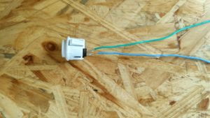
I was led to soldering stations to learn how to solder. The task is solder long wires to an arcade button. Since I have learned and practiced soldering in my junior high school, it is quite easy for me to achieve that.
The button switch:

Task 2: Build the circuits
At the beginning, I tried to build the circuits based on schematics given. However, my speaker didn’t work. Then, I asked for fellows’ help and realized that I mistaken the Variable Resistor as Voltage Regulator since they all have three pinouts, without noticing that there are corresponding images at the bottom of the post. I adjusted immediately and the rest of the process went well.
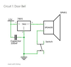
Circuit 1: Door Bell
- 1 * Breadboard: to make it easier to build circuits
- 1 * LM7805 Voltage Regulator: to maintain a constant voltage level
- 1 * Buzzer:an audio signalling device
- 1 * Switch:to turn on or turn off the circuits
- 1 * 100 nF (0.1uF) Capacitor: to store an electric charge, to make the light on when pressing the switch here
- 1 * 12 volt power supply: to supply electricity to the circuits
- Several Jumper Cables (Hook-up Wires): to connect the circuits

When pressing the button, the speaker began to make noise exactly how the door bell works. The circuit worked the same after I changed the switch.
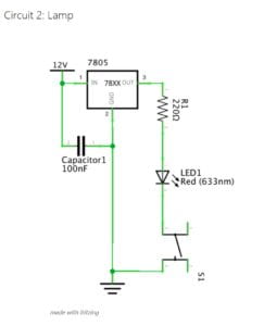
Circuit 2: Lamp
- 1 * Breadboard: to make it easier to build circuits
- 1 * LM7805 Voltage Regulator: to maintain a constant voltage level
- 1 * 220 ohm Resistor:to protect the circuits
- 1 * Switch:to turn on or turn off the circuits
- 1 * LED: a light
- 1 * 100 nF (0.1uF) Capacitor: to store an electric charge, to make the light on when pressing the switch here
- 1 * 12 volt power supply: to supply electricity to the circuits
- Several Jumper Cables (Hook-up Wires): to connect the circuits

On the basis of Circuit 1, by changing the speaker into a LED and adding a resistor, I built Circuit 2 successfully.
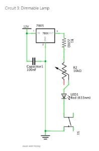
Circuit 3: Dimmable Lamp
- 1 * Breadboard: to make it easier to build circuits
- 1 * LM7805 Voltage Regulator: to maintain a constant voltage level
- 1 * 220 ohm Resistor:to protect the circuits
- 1 * 10K ohm Variable Resistor (Potentiometer): to change the resistance value in the circuit
- 1 * Switch:to turn on or turn off the circuits
- 1 * LED: a light
- 1 * 100 nF (0.1uF) Capacitor: to store an electric charge, to make the light on when pressing the switch here
- 1 * 12 volt power supply: to supply electricity to the circuits
- Several Jumper Cables (Hook-up Wires): to connect the circuits

In Circuit 3, I added a Variable Resistor which changes the resistance value in the circuit. By rotating it, the brightness of LED varied as the photograph below shows.

Question 1:
According to The Art of Interactive Design, interaction basically involves two actors, namely me and the circuit. Although the degree of interaction is quite low since it’s fairly easy, the communication between me and the circuit does exist in the form of sound, light and pressing, so there is interaction from my perspective.
Question 2:
Interaction Design and Physical Computing allow people’s thoughts in mind to come into reality, thus creating Interactive Art. Let’s consider the case of the EyeWriter in Zack Lieberman’s video. With the help of high-technology, the artist are able to interact with the digital devices by his eye movement to draw wonderful paintings.