In the first recitation, I built a paddle button with my partner.
These are the materials for our project.
- 1 * Breadboard
- 1 * Buzzer
- 1 * Push-Button Switch
- 2 * 220 ohm Resistor
- 1 * 10k ohm Variable Resistor (Potentiometer)
- 2 * LED
- 1 * 5 volt power supply
- 1 * Barrel Jack (Power)
- 1 * Multimeter
- 1 * DIY Paddle Button
- Several Jumper Cables (M/M Wires)
Now, let’s start!!!
TASK1
STEP 1
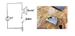
This is the circuit diagram of our first step.This is a device that controls a buzzer by pressing a button. We found that the current flows from the red line through the button, then into the other red line, then into the buzzer, and finally into the black line, into the negative terminal, and together they form a complete circuit. We tried to make the Buzzer speak.
STEP 2
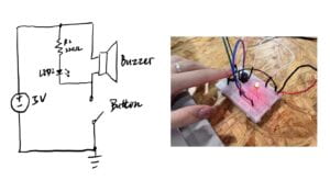
In step2, we added a LED in our circuit. But at first, the LED always lit and was out the control of our switch. We found that it was because we missed the meaning of series circuit and parallel circuit. After a second try, it worked!
In this device, buttons control both the buzzer and the LED. When we press the button, the buzzer sounds and the LED lights up at the same time. The current flows from the positive terminal, first through the button, and then divides into two routes. One flows through the speaker, the other through the LED and the resistor, and the two currents merge into a single current that flows into the negative terminal.
STEP3
https://drive.google.com/file/d/1Tktlvk27QxY-vqw-_6is5OdxsmF7ylVQ/view?usp=sharing
The area of the Breadboard whole was very small, so we used a lot of cables to help us connect the circuit smoothly. At first, the LED didn’t light up when we turned the sliding rheostat. We checked the circuit and found that there was no problem of circuit. My partner thought that the LED was broken. When we changed an LED, the circuit was successfully connected.
This circuit had a total of three branches, and through the button to control the buzzer and two LEDs at the same time. By rotating the knob on the variable resistor we were able to change the resistance value of it and thus change the brightness of the LED on the branch with an LED, a resistor, and a variable resistor.
TASK2
We went to soldering stations with cardboard, copper tape, and wires to build a switch. We used special scissors to remove 1.5 cm of insulation part from both ends of the wire to reveal the metal part inside in order to form a circuit. When we chose the wrong opening for the scissors, we accidentally cut the wire. After testing, I found that the second small opening was the most suitable.
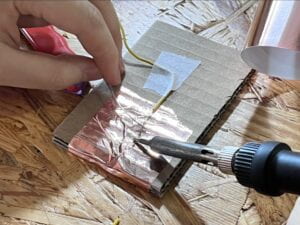
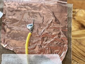
It was difficult for us to solder the wire. We had to wait a while for the welding to heat up. One of us was responsible for holding the cardboard, one of us was responsible for welding, and we needed to heat the wire in the same place to melt it into a ball, and then cool it. It didn’t form a ball, as the professor had demonstrated, but it held the wire in place. Though it didn’t look good, it successfully worked.
TASK3
After we had completed the DIY paddle switch, we replaced the push button with the newly soldered DIY paddle.
And then, we used the morse code* chart below, chose a 4-letter secret word ”LOVE” and sent it to another team on the table next to us.
https://drive.google.com/file/d/14HR2Vq4UOi0bl7QS64UdFJ6h-qx_0_2c/view?usp=sharing
Here is the relevant video.
PS. I am very poor at physics , so I was very grateful to my partner for helping me and explaining the working principle of the circuit. We succeeded ultimately.
Additional Required Questions
- Question 1: What is the function of the resistor R1?
LEDs need resistors to help limit the current that passes through them so they do not get damaged. Every LED has a current rating that should not be exceeded and resistors have the ability to limit the current to below the maximum allowable current allowed for the LED. In short, the resistor acts as a protection
- Question 2: Looking at the following circuit, draw its diagram by yourself.
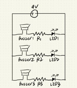
- Question 3: After reading The Art of Interactive Design, in what way do you think that the circuit you built today includes interactivity? Which degree of interactivity does it possess? Please explain your answer.
I think the circuit I built today is highly interactive. When I performed an action, the device gives me interactive feedback. For example, when I press a switch, the interactive information is sent to the buzzer and LED with an electric current, causing them to sound or light up to transmit the information to the outside world. When other people hear a sound or see a light, they interact with me to make it interactive.
- Question 4: How can Interaction Design and Physical Computing be used to create Interactive Art? You can reference Zack Lieberman’s video or any other artists that you know.
According to Zack Lieberman’s video, he and other artists use both interaction design and physical computing to help paralyzed people create their own art. Although they can’t move physically, they are still creative. So Zack created it by capturing their eye movements and then weaving the path of those eye movements into lines that appeared on the screen. This is not only a combination of technology and art, but also a humanistic concern. Similarly, there are devices that Stephen Hawking used in the later stages of his Parkinson’s disease, and he also used this interactive art to communicate with the outside world.