In this recitation, I built three circuits: Circuit 1: Fade, Circuit 2: Tone Melody, and Circuit 3: Speed Game. Then I ran them through the example code.
Here are all the materials i used:
- 1 * Arduino Uno
- 1 * USB A to B cable
- 1 * Breadboard
- 1 * Buzzer
- 2 * LEDs
- 2 * 220 Ohm resistors
- 2 * 10 kOhm resistors
- 2 * Pushbuttons
- A handful of jumper cables
- 1 or more * DIY paddles (cardboard buttons from Recitation 1)
- 1 * Multimeter
- 1 * USB-C adapter
This time, we got our own toolkit with everything we need exactly (besides the USB-C adapter)
Circuit 1: Fade
I worked individually to build the “circuit 1: Fade” following the circuit-building part of the instructions. I assembled the wires connected to the power supply on the breadboard and then the register, the LED, and the wire connecting them in turn. I connected the anode (the longer, positive leg) of LED to digital output pin 9 on my board through a 220 ohm resistor and connected the cathode (the shorter, negative leg) directly to ground.
When I finished building, I accessed the code from Arduino IDE > File > Examples > 03.Analog > Fading and uploaded it to my Arduino. It didn’t work at the first time, because I put two sides of the cable both on the negative one. I asked Cissy, who sat next to me, got it changed and it worked!
This circuit was designed to control the LED,but without a push button. With the code provided, the LED will light and dim rhythmically. Jut as the video showed.
Circuit 2: tone Melody
I then changed the LED into a Buzzer, I accessed the code from Arduino IDE > File > Examples > 02.Digital > toneMelody and uploaded it to my Arduino. But it didn’t work at first, I asked the lecture assistant for help. She told me that I forgot to change the digital output pin9 into 8. Right after I changed my wire, it worked again and the buzzer played a melody.
Here is my physical circuit.
Circuit 3: Speed Game.
This is a two-player game where each participant races to click a button more quickly than their opponent. Whoever has clicked their button ten times the fastest wins!
This time, the circuit is a little bit more complex. In order not to make any mistakes in case the circuit won’t work, I followed the steps of the instructions one by one, even the insertion of the wire is consistent with the example. However, the circuit didn’t work after I uploaded. I checked with the assistance of LA and found that I didn’t choose the right USB port. Also, I found that whether we used capital letters when we are coding matters. For example, digitalWrite must have a “W”. What’s more, at the last of each line of code, there should be a “;”. After I changed all of them , it finally worked. I played with Cissy, and unfortunately, i lost:(
Here is the video.
We switched out the push buttons with the DIY paddles we soldered during the previous recitation and had another game by pressing the Reset button (the little red one!) on my Arduino Board. Guess what, i lost again:)
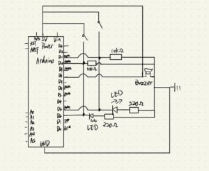
Here is my own circuit. This is a circuit with both series and parallel connections, where one switch controls one bulb, but they are all connected to the same Buzzer.

Question 1: Propose another kind of creative button I could use in Circuit 3 to make the game more interactive.
Add another speaker to the game, and when one side is halfway through the game, have the buzzer say “uh-oh” as a cue to both players. Besides, add another two buttons, when the player presses the button, the press already valid by the player can be cancelled. This can add interest and urgency to both players.
Question 2: Why did we use a 10 kOhm resistor with each push button?
The resistor provides a connection to ground, which is relevant when the button is not pressed.If we ignore this connection, the input pin sometimes won’t connect to anything (the left side is “floating”), essentially acting like an antenna (reading in random values).
To ensure that we always read LOW when the button is not pressed, we added a 10 kOhm resistor as a pull-down resistor.
In addition, if the provided resistance value is too small, then the circuit is prone to short circuit, so the 10kOhm resistance was selected.
Question 3: SCOOT system is an adaptive control system developed by the Institute of Transport and Road Research in the United Kingdom.
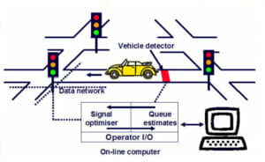
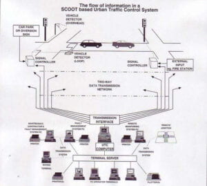
Here’s a module of the system.


It controls the junction or part of the crosswalk road network according to the direction of arrival of each node (i.e., each node on the connection) from each cycle of the signal in the balance of transportation, traffic related and continuous periods, considering the change in traffic demand of the nodes. For each change, the red and green lights change. Not only that, the system administrator can also adjust the traffic light timing according to the real-time situation, such as providing green protection for fire engines and ambulances.
And this exactly satisfied with the explanation in the reference book “We strive to find a simpler and faster way to prototype in the cheapest possible way.” And this system also reduce the interruptions to the flow and have collaborated with all sides.
The different nodes are like digital interfaces on a scaled-up Arduino, and each change in real-time traffic volume is like a different program for different variables in Arduino programming. I choose this project not only because it is interesting, but also it is very utilized, unlike the fixed traffic light in China.
Here is a related URL: https://www.traffictechnologytoday.com/news/event-news/trl-showing-latest-version-of-scoot-software-at-highways-uk-2019.html