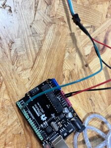
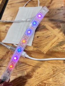
In this recitation class, I tried to combine music and visual LED lights together and made them more interactive.
I first connected the LED with the Arduino and downloaded the library. 

In the serial monitor, I entered 4 numbers. The first one means which LED will light, and the following three will define its color.
In the next step, I used processing to control the LED lights. I have to add serialRecord coding, or it will not connect with the Arduino.
Here is my initial coding. In this part, I tried to make the LED light the color white with the music I selected. It will shine randomly and change its intensity with the volume. The coding in Processing:
import processing.sound.*;
import processing.serial.*;
import osteele.processing.SerialRecord.*;

Serial serialPort;
SerialRecord serialRecord;
SoundFile sample;
Amplitude analysis;
int NUM = 60;  //amount of pixels
int[] r = new int[NUM]; //red of each tile
int[] g = new int[NUM]; //red of each tile
int[] b = new int[NUM]; //red of each tile

void setup() {
  size(640, 480);

  // load and play a sound file in a loop
  sample = new SoundFile(this, "11.mp3");
  sample.loop();

  // create the Amplitude analysis object
  analysis = new Amplitude(this);
  // analyze the playing sound file
  analysis.input(sample);
   String serialPortName = SerialUtils.findArduinoPort();
  serialPort = new Serial(this, serialPortName, 9600);
  serialRecord = new SerialRecord(this, serialPort, 4);
  serialRecord.logToCanvas(false);
  rectMode(CENTER);
}

void draw() {
  println(analysis.analyze());
  background(125, 255, 125);
  noStroke();
  fill(255, 0, 150);

  // analyze the audio for its volume level
  float volume = analysis.analyze();

  // volume is a number between 0.0 and 1.0
  // map the volume value to a useful scale
  float diameter = map(volume, 0, 1, 0, width);
  float light = map(volume, 0, 1, 0, 255);
  int n = int(random(60));
    r[n] = floor(light);
    g[n] = floor(light);
    b[n] = floor(light);
    serialRecord.values[0] = n;     // which pixel we change (0-59)
    serialRecord.values[1] = r[n];  // how much red (0-255)
    serialRecord.values[2] = g[n];  // how much green (0-255)
    serialRecord.values[3] = b[n];  // how much blue (0-255)
    serialRecord.send();
  // draw a circle based on the microphone amplitude (volume)
  circle(width/2, height/2, diameter);
}
Here is my final coding: I change the color of the background. At first, it didn’t work when I merely apply the millis coding. So I asked my professor and int the startTime. It will change its color during the first 4.5 seconds from green to white to black. Also, there is a circle that will change its size with the volume of the music. I first tried to let the LED light randomly. And finally I found when I apply frameCount instead of the random coding, the LED light will make a wave. I kept them at last because I think they are more beautiful. And I change the coding of r, g, b, so that they can make the LED into different lights instead of only white. And when the volume is high, it will become redder. The coding in Processing:
import processing.sound.*;
import processing.serial.*;
import osteele.processing.SerialRecord.*;

Serial serialPort;
SerialRecord serialRecord;
SoundFile sample;
Amplitude analysis;
int NUM = 60;  //amount of pixels
int[] r = new int[NUM]; //red of each tile
int[] g = new int[NUM]; //red of each tile
int[] b = new int[NUM]; //red of each tile
int startTime;

void setup() {
  size(640, 480);

  // load and play a sound file in a loop
  sample = new SoundFile(this, "11.mp3");
  sample.loop();

  // create the Amplitude analysis object
  analysis = new Amplitude(this);
  // analyze the playing sound file
  analysis.input(sample);
   String serialPortName = SerialUtils.findArduinoPort();
  serialPort = new Serial(this, serialPortName, 9600);
  serialRecord = new SerialRecord(this, serialPort, 4);
  serialRecord.logToCanvas(false);
  rectMode(CENTER);
  startTime = millis();
}

void draw() {
  println(analysis.analyze());

  long t = millis() - startTime;
 if (t < 1500) {
   background(125, 255, 125);
 } else if ((t>=1500) && t<3000) {
   background(255);
 } else {
   background(55);
 }

  noStroke();
  fill(255, 0, 150);

  // analyze the audio for its volume level
  float volume = analysis.analyze();

  // volume is a number between 0.0 and 0.4
  // map the volume value to a useful scale
  float diameter = map(volume, 0, 1, 0, width);
  float light = map(volume, 0, 0.4, 0, 255);
  int n =  frameCount % 60;
    r[n] = floor(light);
    g[n] = floor(255-light);
    b[n] = 0;
    serialRecord.values[0] = n;     // which pixel we change (0-59)
    serialRecord.values[1] = r[n];  // how much red (0-255)
    serialRecord.values[2] = g[n];  // how much green (0-255)
    serialRecord.values[3] = b[n];  // how much blue (0-255)
    serialRecord.send();
  // draw a circle based on the microphone amplitude (volume)
  circle(width/2, height/2, diameter);
}
The coding in Arduino:
#include "SerialRecord.h"
#include

#define NUM_LEDS 60  // How many leds in your strip?
#define DATA_PIN 3
 // Which pin are you connecting Arduino to Data In?
CRGB leds[NUM_LEDS];

// Change this number to the number of values you want to receive
SerialRecord reader(4);
void setup() {
 Serial.begin(9600);
 FastLED.addLeds<NEOPIXEL, DATA_PIN>(leds, NUM_LEDS);  // Initialize
 FastLED.setBrightness(10); // BEWARE: external power for full (255)
 //further info at https://learn.adafruit.com/adafruit-neopixel-uberguide/powering-neopixels
}

void loop() {
 if (reader.read()) {
   int n = reader[0];
   int r = reader[1];
   int g = reader[2];
   int b = reader[3];

   leds[reader[0]] = CRGB(reader[1], reader[2], reader[3]);  //  Prepare the color information using CRGB( Red, Green, Blue
   FastLED.show();  //  Pass the information of color to the LED
 }
}
Here is my final video: