Task #1: Make a Processing Etch-A-Sketch
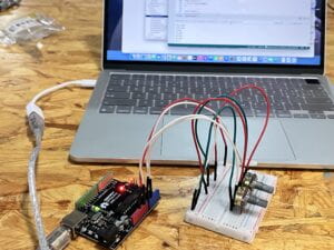
I connected two potentiometers to the Arduino board. I check it on the Arduino with the serial Monitor. Here is my circuit:
 It worked well!
Like an Etch-A-Sketch, one potentiometer should control the circle’s x-axis movement, and the other should control the circle’s y-axis movement. So I edited the code in Processing( Always remember to close the serial monitor in Arduino because otherwise, I will see no port🤯)
Here is my coding in Processing:
import processing.serial.*;
import osteele.processing.SerialRecord.*;
float px ;
float py ;
Serial serialPort;
SerialRecord serialRecord;

void setup() {
  fullScreen();
  background(102);
  String serialPortName = SerialUtils.findArduinoPort();
  serialPort = new Serial(this, serialPortName, 9600);

}

void draw() {
  serialRecord.read();
  int value1 = serialRecord.values[0];
  int value2 = serialRecord.values[1];

  float x = map(value1, 0, 1024, 0, width);
  float y = map(value2, 0, 1024, 0, height);
  strokeWeight(4);
  stroke(255);
  line(x, y, px, py);
  px = x;
  py = y;

}
SerialRecord will relate to my two potentiometers. I changed the example coding the circle into the line and rewrote it with the coding px, py so that it will be a continuous line. I first thought my coding was wrong because it didn’t work. Then I found it interesting that if I don’t define the color of the background and the stroke, I cannot see the line. Because the initial coding makes the line’s color black as well. And if I add a background code into the void draw part, then there will only be a dot on the screen instead of the line because it will make the background draw repeatedly.
Here is my coding of Arduino: I had to make sure that the analogRead relates to the Arduino board.
#include "SerialRecord.h"

// Change this number to send a different number of values
SerialRecord writer(2);

void setup() {
  Serial.begin(9600);
}

void loop() {
  int sensorValue1 = analogRead(A0);
  int sensorValue2 = analogRead(A1);
  writer[0] = sensorValue1;
  writer[1] = sensorValue2;
  writer.send();
  delay(10);
}
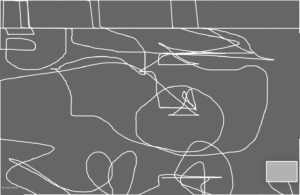
I then tried to draw with it, but very unfortunately my vision and the actual operation were very inconsistent. I was hoping to draw a landscape with a sun in the top left corner of the screen, grass at the bottom, and many small animals in the middle. But when I did it, what I drew was very abstract. I think the most difficult part is drawing with processing😭.
Here are my drawing and the video:

Task #2: Pair Working
My partner is Cissy Linx, Xie
The initial code for the circle that Cissy will bounce back and forth is completed when I connect the servo motor to the circuit. To make it more beautiful and interactive, I changed the code for Processing. I changed the color of the background to dark blue and also changed the circle to a pentagram. To make it look more interesting, I set the star’s color to random. I found that by drawing rectangles with transparency in a void draw, I can make the background stack up one layer at a time to achieve the effect of a shooting star.
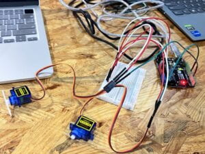
Here is our circuit:

While I was changing the processing, Cissy started to adjust the code of Arduino and we exchanged our code. Arduino needs to read the processing to control the servo, when the pentagram touches the boundary, one side of the servo will turn at a certain angle, we can also change the speed of its rotation, etc. We first wanted to use the delay code, but we found that it would make the computer very laggy.
This is our coding in Arduino:
#include
#include "SerialRecord.h"
long t1;
long t2;
SerialRecord reader(2);
Servo myservo1;
Servo myservo2;

void setup() {
  Serial.begin(9600);
  myservo1.attach(9);
  myservo2.attach(10);
}

void loop() {
  reader.read();
  if (reader[0] ==41) {
  t1=millis();}
  if(millis()-t1<300){ myservo1.write(60); } if(millis()-t1>=300&&millis()-t1<1000){
  myservo1.write(0);
 }


  if (reader[0] ==1401) {
  t2=millis();}
 if(millis()-t2<300){ myservo2.write(60); } if(millis()-t2>=300&&millis()-t2<1000){
  myservo2.write(0);
 }

}
This is the coding in Processing:
int speed=10;
import processing.serial.*;
import osteele.processing.SerialRecord.*;
int x=51;
float r = random(0, 255);
float g = random(0, 255);
float b = random(0, 255);
Serial serialPort;
SerialRecord serialRecord;

void setup() {
  fullScreen();
  background(#232640);
  String serialPortName = SerialUtils.findArduinoPort();
  serialPort = new Serial(this, serialPortName, 9600);

  // In order to send a different number of values, modify the number `2` on the
  // next line to the number values to send. In this case, the corresponding
  // number in the Arduino sketch should be modified as well.
  serialRecord = new SerialRecord(this, serialPort, 2);
}

void draw() {
  fill(#232640, 50);
  rect(0, 0, width, height);
   r = random(0, 255);
   g = random(0, 255);
   b = random(0, 255);
  fill(r, g, b);
  star(x, height/2, 80, 40, 5);
  x=x+speed;
  if(x==41||x==1401){
  speed=speed*(-1);}

  serialRecord.values[0] = x;
  serialRecord.send();}


void star(float x, float y, float radius1, float radius2, int npoints) {
  float angle = TWO_PI / npoints;
  float halfAngle = angle/2.0;
  beginShape();
  for (float a = 0; a < TWO_PI; a += angle) {
    float sx = x + cos(a) * radius2;
    float sy = y + sin(a) * radius2;
    vertex(sx, sy);
    sx = x + cos(a+halfAngle) * radius1;
    sy = y + sin(a+halfAngle) * radius1;
    vertex(sx, sy);
  }
  endShape(CLOSE);
}
This is our final video( Because of the time limit and because we did not have the materials, we didn’t make the hand part).