Task1
Step1
What does the circuit do?
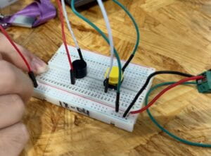
The circuit allows us to sound or silence a buzzer by pressing the button.
How the components make it happen?
The buzzer and the button are connected in series so that the buzzer is subjected to the control of the button. The button serves as a controller. The lateral sides of the button are connected. However, the upper and lower pins are separated by a special design that when the button is pressed, it could break or connect the circuit. The buzzer makes a harsh noise when a current passes through it so that we can make it beep beep by pressing the button and stop it by moving your fingers away.
Challanges?
Of course. We didn’t pay attention to the schematic of the button so that we were unaware of the fact that only the upper and lower pins were separated. Fortunately, it wasn’t rocket science. My partner had astute observation. She noticed the problem on the first sight. So, she suggested we simply rotating it 90 degrees and everything worked fine.
Step2
What does the circuit do?
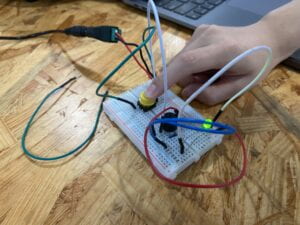
This circuit lights up the green LED while sounding the buzzer when we press the button.
How the components make it happen?
In the second circuit, according to the schematic, a green light-emiting-diode is connected parallel to the former buzzer. However, it’s noteworthy that both the LED and the buzzer and connected in series to the button, meaning that they are at the same time subjected to the control of the button. Also, for the LED to function properly, a protecting resistor is connected in series to it which can essentially limit the current passing through the LED so that it won’t be burnt.
Challanges?
Easy game, boys.
Step 3
What does the circuit do?
For the thrid circuit, the button component is replaced by our handmade switch. So, when we squeeze the two copper foils together, the current passes through and sounds the buzzer as well as lights up the green LED.
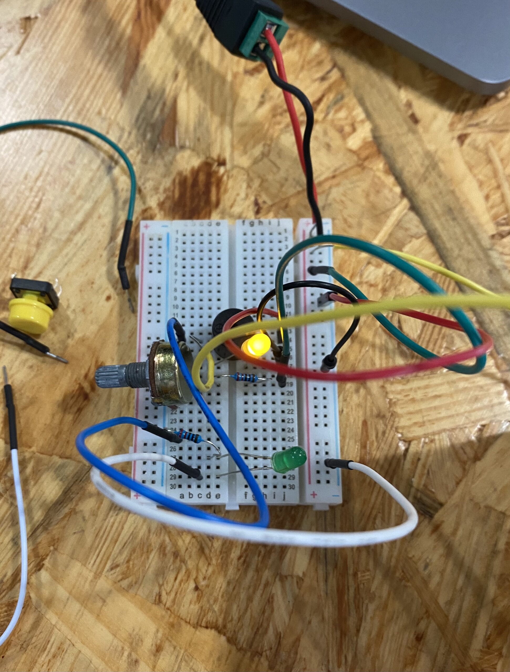
Another feature of the circuit is that, we could adjust the brightness of the yellow LED by turning the knob on the left side of the breadboard. The yellow LED is independant from our handmade switch so that it’s always lit.
How the components make it happen?
We swapped the button with our handmade switch, and they work in similar fashions. The switch allows current to pass through when the two pieces of copper that sticked on the inside of our cardboard clam touches. Otherwise, current should not pass, resulting in breaking the circuit.
The variable resistor literally offers variable resistence. When we turn the knob, the resistence connected into the circuit varies. For this specific branch circuit, since it’s connected in parallel with the other components, the voltage across is simply the voltage over the power supply. With that in mind, as the resistence goes up in the POT, the voltage over the diode drops since components connected in series shares the voltage and with greater resistence comes greater voltage, making the diode dimmer. Vice versa.
Challanges?
Given the asymmtrical design of POT that only the two specific adjoining pins should be connected into the circuit, we were confused for a while. I found the diagram on the website. My brilliant partner quickly identifed the direction the knob should face. I suggested that it would be better if the knob could face outwards so that it would be more handy for us to turn the knob. Thankfully, with the schematic, we easily specified the two pins that we should use and how they should be mounted into the breadboard.
Another problem we faced was that we kinda had the cables a bit tangled together. We spent a minute or two clearing up the jump wires, but still its quite chaotic. It could be neater undoubtedly, but since we were not looking for the best solution in this recitation, I would say I was quite satisfied with the result we got in such a short time.
Task 2
Build a switch!
We used the wire stripper provided to cut two lines of wires down, and afterwards we stripped them partially for later soldering. We put the wire within the gauge on the clipper, applied a bit of pressure, and pull the wire out. My dear partner ran into a problem when she tried to pull off the cable, because the cable was too thin for her to grip if firmly. Luckily, I had some experience doing this kind of work. I simply circled the cable around my index finger and pulled, which creates a much greater grip. Done!
We grabbed two pieces of cardboards and papertaped their narrow sides together. Specially, I folded it one of them a bit at the end so that there would be a resilence force going against our fingers when we press it, namely let it automatically bounce back. Next, we grabbed some coppertape and sticked it to the opening sides.
After the basic framwork was ready, we tried to stick the cables onto the cardboards. Rudi pointed out something truly meaningful, that the cable should be twisted under the tape as shown on the left. This clever trick ensured that cables won’t be pulled out all the way through. A much greater effort has to be made to drag it out. We simply followed the word of wisdom.
Eventually, we came to soldering. Honesyly, this was something that I was quite familiar with (a bit cocky so and so). To fix the wires firmly on the copper tape, I pressed the tip of the solder gun right onto the cable so that it was firmly fixed on the copper surface. After it heated up a bit, I gradually deliver the solder to the heating tip, melting down some solder to cover the cable. As soon as the wire was immersed, I gently rolled the solder gun off so that the metal could cool down while the tip of wire would not jump out. I suppose this would be a better way to do soldering rather than pressing down the cables with a finger cuz it may get quite hot instantaneously.
Task 3
Honestly speaking, my outstanding partner and I were so productive that we finished a bit ahead our fellow deskmates. As a result, we could not play the Morse code with them. Instead, we did a bit cipehr and decipher game ourselves. Down below is what Rin came up with. A complete sentence encoded in Morse code. See if you can decipher it. (You might find it easier with a hint (which course is the nightmare of all freshman students? (*^▽^*)).
Additional required questions
Question 1: What is the function of the resistor R1?
To protect the light-emiting-diode. R1 serves to limit the current running through the LED so as to prevent excess current that may cause permanent damage to it. In the case of this project, we were not carefully deducting the currents and voltages in each branch circuits. So, we couldn’t tell if the curren runs over the threshold. As a result, a ballast resistor was mounted to keep things safe.
Question 2: Looking at the following circuit, draw its diagram by yourself.
Question 3: After reading The Art of Interactive Design, in what way do you think that the circuit you built today includes interactivity? Which degree of interactivity does it possess? Please explain your answer.
The circuit we built could be interactive in two ways. Fisrt of all, when we turn the knob, the LED either goes brigher or dimmer. In more tangible terms, we provides an input which is turning the knob; physics laws process the input and, instantaneously, generates an outcome that the brightness changes. And we may later decide, based on the brightness we see, if further adjustment is needed. Thus, it could be iterable. Adding on to that, when we squeeze the switch, the circuit lights up and beeps. In another word, we inputs the squeeze to the circuit: samewise the input is processed and output is generated, which is the lit LED and a beep. We hear the noise and see the light, and decide if we should hold it for a unit of time or three or whatever. The input, process, and output well fit the definition of interactivity mentioned in the reading.
However, according to the author, I doubt that the circuit only possesses medium interactivity. The author mentions the example of opening and closing fridge to see the light light up and go out repeatedly is a sort of low interactivity for normal adults. And similarly, our circuit works in the same fashion. As the author puts, “this kind of interaction is silly and beneath the intellectual dignity of almost everybody”. I believe our circuit must be slightly beyond silly fridge games, but essentially they share a lot in common.
Question 4: How can Interaction Design and Physical Computing be used to create Interactive Art? You can reference Zack Lieberman’s video or any other artists that you know.
I believe, interaction design can be used to create interactive art in a way that involves audience into the art. According to Tigoe, who prefers to look at an interactive art as an performance, puts “figure out how they might uncover the story, and their own emotional interpretation of the work”. Interactivity isn’t part of the interpretation that may occur in audience mind. Instead, as different audience interact with the art in different ways, generating distinct manifestations of art, which has the great potential to invoke audience differently.
This reminds me of Thomas Heatherwick and his weird spun chair. Charis are scattered in public space with no instrucion provided. Pedestrians touch them, move them, spin them a little bit, trying to get a sense of what they do. As they start to get familiar, they sit on them, momentarility chairs start to spin. From my personal knowledge, the unsecured feeling on the chair causes great panics. So, they stop. Gradually, they figure out that it’s quite safe. They spin faster. Through the course of action, there maybe “emotional interpretation” going on.
Physical computing generally refers to a system that can sense and respond to the change around it, and I believe it is the very technical basic of modern interactive art. As we can see in the case of Tony Kwan mentioned in Lieberman’s video, there’s nothing more critical in their project than the eyetracking system. It senses Kwan’s eye movement and responds to it in such a way that the trajectory of the movement is mapped onto the screen. As a matter of fact, physical computing empowers Lieberman to realize Kwan’s dream. Indeed it’s made up of cold metals and semiconductors but in its vein there is true blood.


Leave a Reply