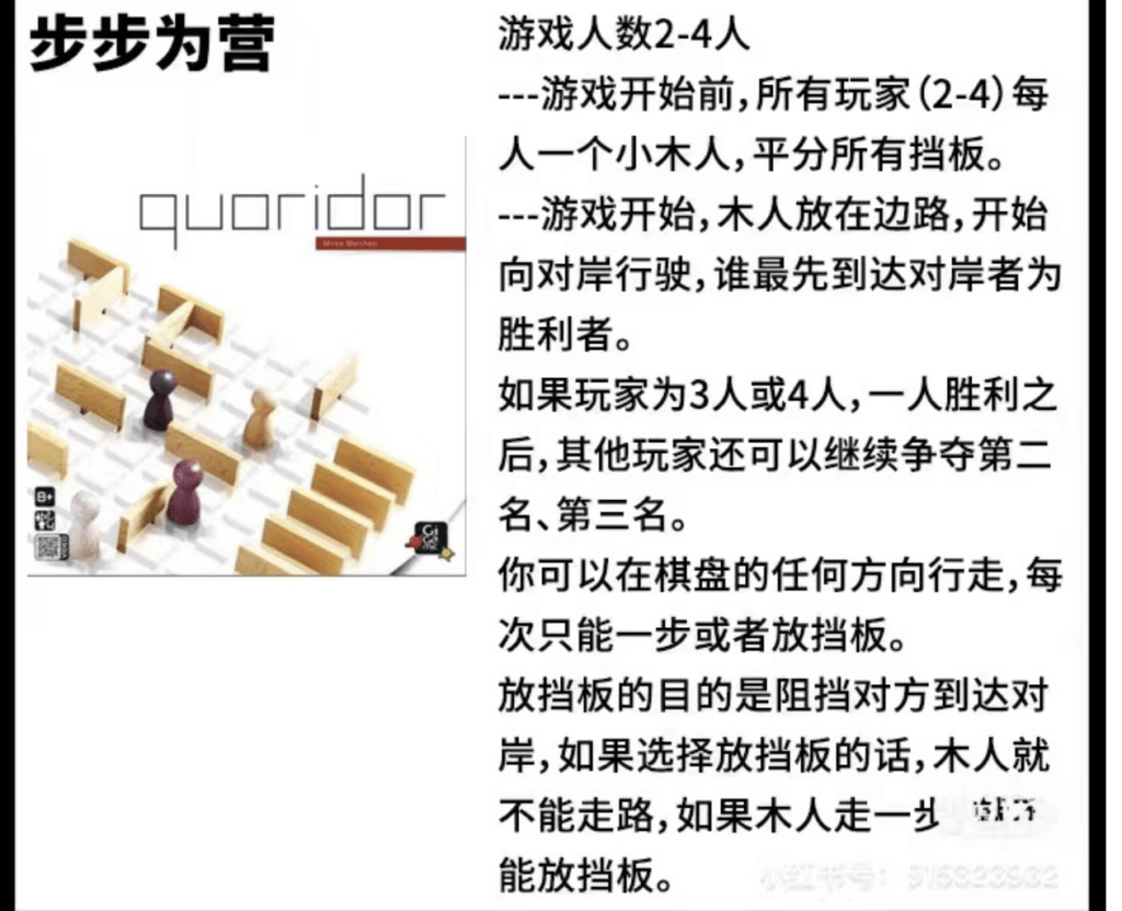
Hello, everyone! Welcome back to Vivian’s Blog! Before I know it, the semester is coming to an end, and I have completed my final project in interaction lab. Next, let me introduce my final project Cross! Black&White and my creative idea and process!This time, I choose to finish the final homework by myself. My instructor is Eric, and I would also like to thank the other two professors, two fellow and three LA from interaction lab for their help in my project!
At the very beginning, I came up with three ideas, one is to make a 3×3 board game, the other is to make an art interactive device shaped like a flower, and the third is to make a robot that can dance. Then I had a meeting with Eric, and he suggested that I choose the first idea because the first idea was more feasible. So I completed my Project Proposal according to the first idea. However, in the early stage of preparing materials and making, I found that the feasibility of my idea was still very limited. (I originally wanted to make a board with 3×3 grids and place a pressing sensor on each grid, use a stepper motor to move the character, and press the pressing sensor to animate the screen.) I need a bigger board for this game to be interesting, but it is difficult to install dozens of sensors on the board. So I asked Eric, Andy and Shengli again. According to their suggestions, I decide to make a 9×9 board and give up sensor and stepper motor but use conductive metal as “button” instead. At the same time I will use the projector to add visual effects. Having decided to make such a “game”, I began to reformulate my idea. I re-integrated and modified the original rules borrowed from and the interaction parts I wanted to add. I’m going to make a game that requires two players. The basic rule of the game is that each player starts from one side of the board and the goal is to go to the other side. Each round, each player can choose to make a move or put a barrier, and placing pieces in some of my interactive parts will give some unexpected instructions, which may be good or bad, affecting the overall outcome of the game.
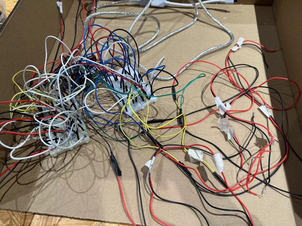
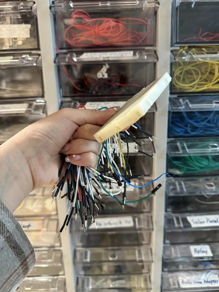
Before the user test, I preliminarily finished my work. I made five grids with interactive parts, and completed the circuit connection and Arduino code production through the previous recitation guidance. As the length of the wire was not long enough, I chose to splice the wires, and chose M/F type wires to ensure good contact between the wires and the breadboard. Then I started to deal with the screen part controlled by processing. I first made five pictures and numbered them to correspond with the five grids with interactive parts. Then I started editing the code, and I ran into some problems along the way. I asked Rachel to help me correct the error of the code, and I asked Kevin about the problem of several grids not working. Kevin helped me find the problem which was two of my resistors met together, resulting in a short circuit. I got some initial interaction with my work after I fixed the circuit. In the user test, my work was successfully tested, and many students came to try my work and put forward many suggestions. For example, increase the number of grids with interactive parts, increase the number of indicators for interactive parts, reduce the number of barriers, and make the indicators appear random. In the improvement and production after user test, I made some adaptations, increased the interactive part from five to twelve, added different sound effects, tried to use the projector and made ten different pictures as instructions (two instructions will appear twice). Then I asked some friends to help me test again and listen to their opinions. I set the number of barriers to nine (reduced to seven again at IMA SHOW). One suggestion I received in user test but I didn’t change in the end was to make the instructions appear random. I tried to do this, but I kept getting code errors. Finally, due to time constraints, I decided to cancel this change, and if I can have more time and opportunities to complete it, I hope to continue to explore how to achieve this random effect!
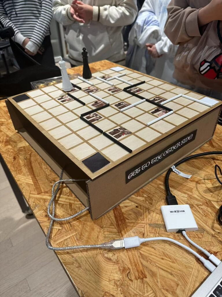
In my entire production and production process, I think my core part is the production of the main body of my project. For the top part of my Project (the side of the chessboard), I selected a 5mm wooden board and carved 9×9 grids by laser cutting method. In addition, I used an electric drill to punch two small holes on both sides of each grid that I needed to make into interactive parts to facilitate the insertion of wires. Then, conductive metal was affixed to both sides of the holes. And I tape the wire to the conductive metal. For the base and sides of the project, in order to facilitate modification and decoration, I used cardboard. As for chess pieces and barrier, I used 3D printing technology to print two pieces, one black and one white, and ten sticks each with a length of two grids. Then, I also attach conductive metal to the bottom of the chess piece, so that when the chess piece is placed on the grid with conductive metal, it acts as a switch that is pressed, connecting the entire circuit and triggering the effect. Because I was concerned about the need for adjustment in the later stage, I did not weld all the wires and conductive metals at once, which also led to the poor contact effect of my works in the early stage. After trying various methods such as changing the type of wire, taping, etc. I welded the last three grids (the contact was the most unstable), so that every part of my interaction worked properly. After confirming that the connection was correct, I glued my project together with glue and printed some stickers for decoration. I also found that the projector wires were not long enough to project the image directly onto the board, so I quickly made a screen out of cardboard and white paper, laid the projector flat, and projected the image onto the screen.
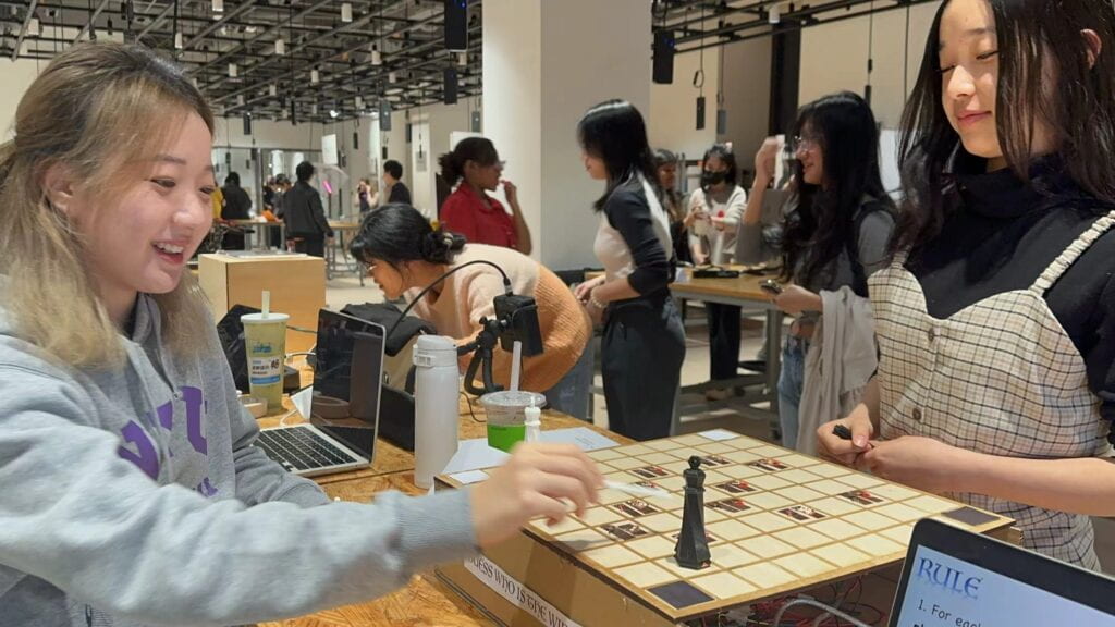
My project was successfully presented in the presentation and IMA SHOW. As a game that requires both strategy and luck, many classmates and friends played it very happily, which gave me a sense of achievement. The pieces will have different sounds and images when they are placed in different positions, so that the player can give feedback according to the instructions and take the next action, which also fits my definition of interaction. If I had more time, I think I would continue to improve the look of my work, and follow Kevin’s advice to make the interactive part of the content random to increase the playability. All in all, this is a work that is particularly meaningful to me. First of all, this is the first time for me to complete a project independently in the interaction lab course. I conceived it myself, designed it myself, assembled it myself, and modified it with my own advice. In this process, although I choose to work individually, I am not without support. I was helped by a lot of friendly classmates and professors. It was fun and rewarding to work together, give each other suggestions and try out each other’s work. Every late night in the studio is no longer cold because of the warmth of the IMA family. In this experience, I made the appearance of the project and 12 interactive parts, which improved my hands-on ability and creativity. When I found that the previous plan was not feasible, I re-thought the plan decisively, and improved my ability to respond to changes. Having experienced both failure and success, I developed a stable state of mind and became a better version of myself.
Some other feelings: My interaction lab trip is coming to an end here. Looking back on this semester, I really learned a lot, felt a lot, and improved a lot. I met a lot of great professors, fellow, LA, classmates here, and made a lot of great memories. I felt deeply again that at IMA nothing is impossible, nothing is set in stone and everyone is an artist. Thanks for everyone. We will meet again in the following semester!
RECORD
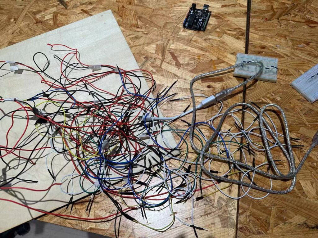
Circuit:
Outlook:
Some friends tried my project:
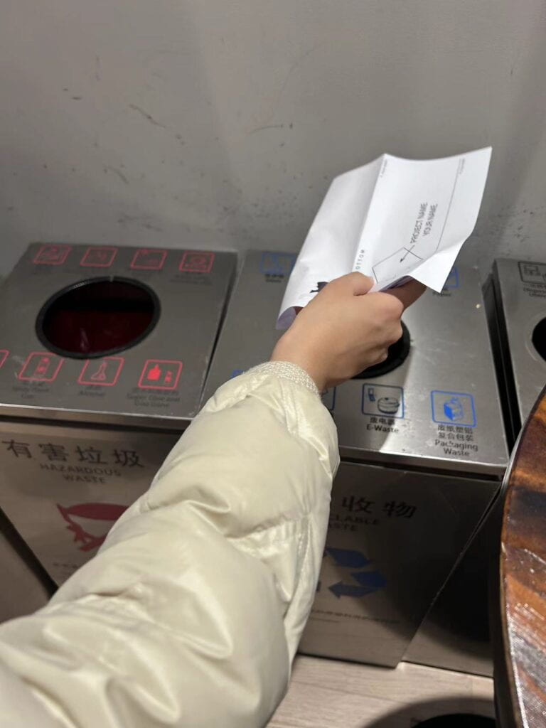
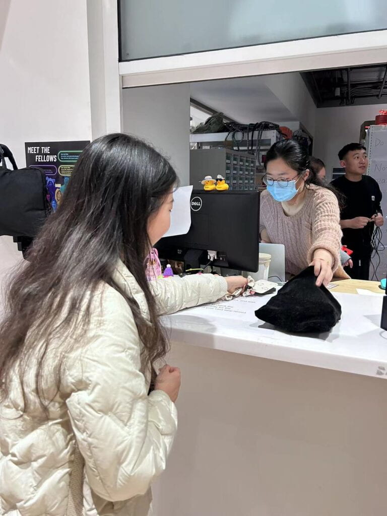
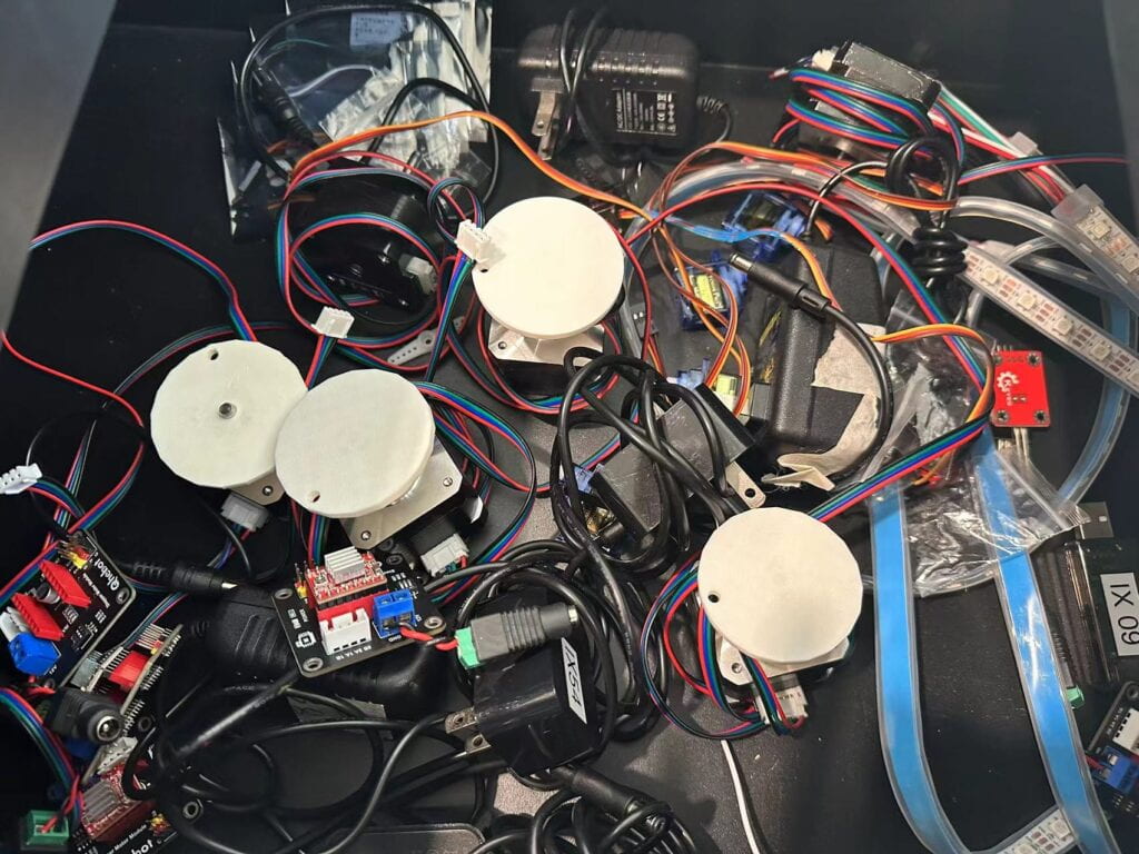
Recycle:
After IMA SHOW
VIDEOS
https://drive.google.com/file/d/1WNrvBxaFh4KdRReKc2pUFncZaFmuR9VG/view?usp=sharing
https://drive.google.com/file/d/1lE3OSnfmYwK00DPpQHaQWO9d-6g3o2TX/view?usp=sharing
APPENDIX
Here’s my code:
Arduino
void setup() {
Serial.begin(9600);
}

void loop() {
// to send values to Processing assign the values you want to send
// this is an example:
int sensor0 = digitalRead(3);
int sensor1 = digitalRead(4);
int sensor2 = digitalRead(5);
int sensor3 = digitalRead(6);
int sensor4 = digitalRead(7);
int sensor5 = digitalRead(8);
int sensor6 = digitalRead(9);
int sensor7 = digitalRead(10);
int sensor8 = digitalRead(11);
int sensor9 = digitalRead(12);
int sensor10 = digitalRead(13);
int sensor11 = digitalRead(2);
// send the values keeping this format
Serial.print(sensor0);
Serial.print(","); // put comma between sensor values
Serial.print(sensor1);
Serial.print(",");
Serial.print(sensor2);
Serial.print(",");
Serial.print(sensor3);
Serial.print(",");
Serial.print(sensor4);
Serial.print(",");
Serial.print(sensor5);
Serial.print(",");
Serial.print(sensor6);
Serial.print(",");
Serial.print(sensor7);
Serial.print(",");
Serial.print(sensor8);
Serial.print(",");
Serial.print(sensor9);
Serial.print(",");
Serial.print(sensor10);
Serial.print(",");
Serial.print(sensor11);
Serial.println(); // add linefeed after sending the last sensor value

// too fast communication might cause some latency in Processing
// this delay resolves the issue
delay(20);

// end of example sending values
}
Processing:
import processing.sound.*;

import processing.serial.*;

SoundFile sound1;
SoundFile sound2;

Serial serialPort;

int NUM_OF_VALUES_FROM_ARDUINO = 12; /* CHANGE THIS ACCORDING TO YOUR PROJECT */

/* This array stores values from Arduino */
int arduino_values[] = new int[NUM_OF_VALUES_FROM_ARDUINO];
PImage photo1;
PImage photo2;
PImage photo3;
PImage photo4;
PImage photo5;
PImage photo6;
PImage photo7;
PImage photo8;
PImage photo9;
PImage photo10;
PImage photo11;

//boolean sound1Played = false;
//boolean sound2Played = false;

boolean square1sound = false;
boolean square2sound = false;

void setup() {
size(900, 900);

noStroke();

printArray(Serial.list());
// put the name of the serial port your Arduino is connected
// to in the line below - this should be the same as you're
// using in the "Port" menu in the Arduino IDE
serialPort = new Serial(this, "/dev/cu.usbmodem1101", 9600);

sound1 = new SoundFile(this, "music1.wav");
sound2 = new SoundFile(this, "music2.wav");

photo1 = loadImage("1.jpg");
photo2 = loadImage("2.jpg");
photo3 = loadImage("3.jpg");
photo4 = loadImage("4.jpg");
photo5 = loadImage("5.jpg");
photo6 = loadImage("6.jpg");
photo7 = loadImage("7.jpg");
photo8 = loadImage("8.jpg");
photo9 = loadImage("9.jpg");
photo10 = loadImage("10.jpg");
photo11 = loadImage("BG.jpg");

}

void draw() {
background(255);
image(photo11, 0, 0, width, height);
stroke(255);

if(keyPressed && !sound1.isPlaying()) {
sound1.play();
}

// receive the values from Arduino
getSerialData();

if (arduino_values[0] == 1) {
image(photo5, 0, 0, width, height);
if (square1sound == false && !sound1.isPlaying()) {
sound1.play();
}
} else {
square1sound = false;
}

if (arduino_values[1] == 1) {
image(photo1, 0, 0, width, height);
if (square1sound == false && !sound1.isPlaying()) {
sound1.play();
}
} else {
square1sound = false;
}

if (arduino_values[2] == 1) {
image(photo4, 0, 0, width, height);
if (square2sound == false && !sound2.isPlaying()) {
sound2.play();
}
} else {
square2sound = false;
}

if (arduino_values[3] == 1) {
image(photo3, 0, 0, width, height);
if (square2sound == false && !sound2.isPlaying()) {
sound2.play();
}
} else {
square2sound = false;
}

if (arduino_values[4] == 1) {
image(photo2, 0, 0, width, height);
if (square1sound == false && !sound1.isPlaying()) {
sound1.play();
}
} else {
square1sound = false;
}

if (arduino_values[5] == 1) {
image(photo10, 0, 0, width, height);
if (square2sound == false && !sound2.isPlaying()) {
sound2.play();
}
} else {
square2sound = false;
}

if (arduino_values[6] == 1) {
image(photo7, 0, 0, width, height);
if (square1sound == false && !sound1.isPlaying()) {
sound1.play();
}
} else {
square1sound = false;
}

if (arduino_values[7] == 1) {
image(photo8, 0, 0, width, height);
if (square2sound == false && !sound2.isPlaying()) {
sound2.play();
}
} else {
square2sound = false;
}

if (arduino_values[8] == 1) {
image(photo9, 0, 0, width, height);
if (square1sound == false && !sound1.isPlaying()) {
sound1.play();
}
} else {
square1sound = false;
}

if (arduino_values[9] == 1) {
image(photo6, 0, 0, width, height);
if (square2sound == false && !sound2.isPlaying()) {
sound2.play();
}
} else {
square2sound = false;
}

if (arduino_values[10] == 1) {
image(photo8, 0, 0, width, height);
if (square2sound == false && !sound2.isPlaying()) {
sound2.play();
}
} else {
square2sound = false;
}

if (arduino_values[11] == 1) {
image(photo10, 0, 0, width, height);
if (square2sound == false && !sound2.isPlaying()) {
sound2.play();
}
} else {
square2sound = false;
}
}

//println(arduino_values[0]);

// use the values like this:
//float x = map(arduino_values[0], 0, 1023, 0, width);
//float y = map(arduino_values[1], 0, 1023, 0, height);

//rectMode(CENTER);
//rect(width/2, height/2, x, y);


// the helper function below receives the values from Arduino
// in the "arduino_values" array from a connected Arduino
// running the "serial_AtoP_arduino" sketch
// (You won't need to change this code.)

void getSerialData() {
while (serialPort.available() > 0) {
String in = serialPort.readStringUntil( 10 ); // 10 = '\n' Linefeed in ASCII
if (in != null) {
//print("From Arduino: " + in);
String[] serialInArray = split(trim(in), ",");
if (serialInArray.length == NUM_OF_VALUES_FROM_ARDUINO) {
for (int i=0; i<serialInArray.length; i++) {
arduino_values[i] = int(serialInArray[i]);
}
}
}
}
}

Citation:
Original rules:
