IX Lab Final documentation: Alien Allure – Vilius Schmidt & Tina Xu – Gottfried Haider

Concept and Design

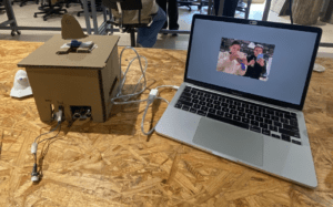
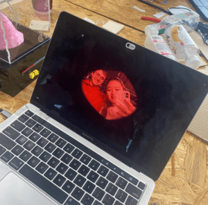
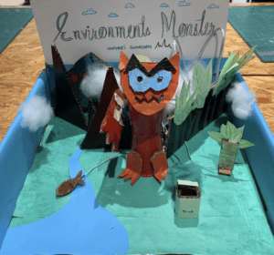
Description: The original concept of a “pet alien” was greatly conserved while realizing and building the final artifact “Alien Allure.” The interactive art project “Alien Allure” involves the user interacting with an alien inside its containment chamber. Due to its contained nature, the interactions possible with the alien are relegated to influencing its environment. This can be done by feeding the alien with a push of a button or changing the internal temperature of its environment with a sliding potentiometer. The project is interactive due to the nature of how the alien reacts due to you changing its internal environment. On the computer window behind the alien enclosure, a webcam feed displays the “vision” of the alien, allowing you to see your effect on the alien’s internal world. When fed, burgers bounce around the screen, when the temperature is changed from hot to cold its vision tints red to blue. This is accompanied by the sound play through processing. The alien chirps with joy when fed, but shivers in the cold.  To increase the liveliness of the alien in the enclosure, a distance sensor is integrated into the interface allowing the alien to sense your presence. When you are need the alien shaking in excitement, however when you are far he becomes docile and moves minimally. With the evident button and sliding potentiometer, as well as the feedback from getting close to the alien enclosure, we believed that this would entice people to explore the functionality of the alien enclosure without prompt so that they could ascertain the story of the alien for themselves. With a simple enclosure with a name tag and sensors we hoped that the way in which the alien could be interacted with would be apparent, and the reactions would be immediate and obvious. 

Video of Final Iteration

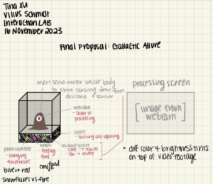
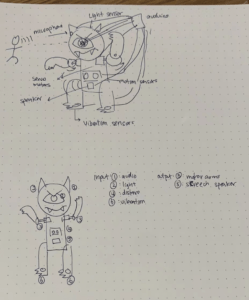
image of original proposal. 

Influences: When thinking of an idea for this project, digital pets such as tamagotchi were inspiration. In our feedback on our project, tamagotchi was brought up in reference to the project. I am glad that the inspiration came through despite out “digital pet” was a physical alien object. Like a tamagotchi the user is only allowed simple interactions like feeding playing and cleaning, However the reactions and interactions make it something worth while and enticing. This was an important aspect in the design process. The alien is happy when it is hot, it is shivering when it is cold, and it shakes when you are near. there is a blend of movement, visual change, and sound. 

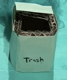
User Testing: Before user testing the alien was a cardboard prototype with the computer towards the side, a potentiometer for temperature (not-sliding), and without any sound. 

Some of the most important additions to the final project (other than upgrading from cardboard to laser cut acrylic and a silicone alien) where the aforementioned things missing from the project. Previously the idea of adding sound had not crossed my mind in the development process, but did well to bringing life to the alien, as well as concrete feedback that “something was happening.”  While many people were queued into the sensors, many were confused with what was happening. why did burgers appear on the screen when the button was pressed, why does the screen have a camera? what is the point of the color changes? from these questions I realized that a failure in presentation was creating conclusion. the idea that the alien was in an enclosure, and the the screen was the POV of the alien was lost. A simple fix to this was creating the lid for the alien enclosure, as well as putting the computer behind the enclosure, so it is evident that whatever is going on the screen is directly related to the aliens environment. This change was suggested multiple times. Finally the sliding potentiometer became the temperature modulating mechanism as it was easier to read. While the screen and the sound was quite effective in bringing the allusion to life, the sliding temperature sensor was still hard to read. As the computer monitor was behind two layers of clear acrylic, people did not resgister the change in color on the moniter when the temperature slider was changed. The location for the potentiometer may have been a bigger issue as due to it being on the side people could not easily see that it modulated temperature. 

Fabrication and Production

Key Step 1: Sensor Test

The first step in creating the project was to determine the sensors we were going to used, and the values that were determined by these sensors. We chose to use a  potentiometer as it was able to change values in an analog manner like a thermostat, which was to become its purpose. Another sensor was a button, this yes and no input would work perfect for feeding the alien. The distance sensor was also used in order to add interaction to the physical bodie of the alien that controls a servo motor that rotates back and forth. Each of these sensor are the most intuitive for their interaction type. Sliders and buttons are commonly seen on a tech apparatus. 

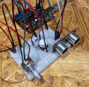
An arduino code was then generated to read the values for each of the sensors in the same sketch.  

Key Step 2:  Alien Vision 

The processing file was then separately created to text the effects on the screen that was constitute the “alien’s vision”. The two interaction that I wanted seen on the screen was the change in temperature and the feeding. To do this a sketch was created in which the processing video library was imported and the video being played in the draw function was the footage taken from the web cam. The window was then set to the size of the web cam footage, as the footage did not cover the whole screen. To generate the tint effect one tint function was set up in front of image (cam, 0, 0) function to tint the color of the video footage. In the tint functions the RBG values became function, in which the mouse position effected the color of the tint. For the red tint for hot, the blue and green were diminished as mouse approached x=0, for the cold tint, red was diminished when x approached it maximum. When trying to implement feeding, an array was created that would generate burgers. Values were set for initial position, initial speed in the x and y direction. And the values were then set to bounce when reaching the boundary conditions of the screen. The initial intention was for that at each button press the number of values in the array would increase, however, this was out of my ability, and thus the idea that the button state would visualize the array was implemented. This was done by putting in a conditional that when the mouse was pressed, the array of 20 burgers was implemented so that they would bounce once reaching the edges of the screen by reversing their velocities. 

Key Step 3: Putting it all together

The Arduino code was updated in order to import the servo motor library and the servo motor was attached to the Arduino chip. Then conditionals were set in regards to the distance read in the distance sensor. There were 3 teirs in which the distance was at a maximum, the distance was a “50” to “20” and when the distance was at “20” to “0”. In each conditional the servo was set to sweep back and forth. the closer to the distance sensor, the faster the sweeping (done by decreasing the delay) and the greater the angle that was swept. The Processing code was then copy and pasted into the serial communication AtoP Processing code in order to obtain the values from Arduino. The values to be received by the processing code were 3, one pot, one slide pot, and one button, and thus the code was set to receive 3 values from Arduino. We had difficulty figuring out how to send Arduino code to the processing code. However, I was taught by simple printing the values of the Arduino code on the same line the processing could read the 3 values from Arduino. Finally the processing code was modified in order to replace the button press for burgers with the digital values from the button connected to processing, and the x coordinated controlling the tint were replaced by the mapping of the analog Arduino values. Finally a cardboard box was created and a prototype of our alien (made of cardboard) was tapped to the servo motor. The Arduino was placed under the box, the sensors were exposed, and the servo motor was stuck through the top for the alien to move. 

This a video of the project at the user testing stage

Key Step 4: Post User Testing

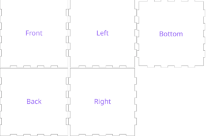
The first part of updating our project was laser cutting out of acrylic instead of a cardboard box. This was done in cuttle.xyz by looking through some of the templates for making boxes. These were then modified to fit a 5×5 inch box that was half as short. This was then modified by cutting out holes for the sensors to fit through. These were measured against the size of the sensors to be the right size. This box was then cut out of black acrylic. 

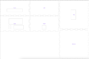
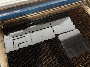
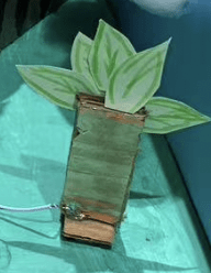
There was an issue with the hole for the slid pot being on the back instead of the side, however this was easily remedied by laser cutting the same sized hole on the side piece separately. Then out of clear acrylic a “glass bubble” was printed to contain the alien. 

   This was then sealed with adhesive. 

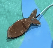
The alien mold was then 3d printed. This was done by creating a 3d model in tinkercad. It was created by fusing a few basic shapes together. The 3d print is shown down below. 

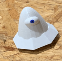
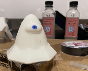
The aline then was created by pouring polymer iver the mold. When two bottles A and B where mixed and painted onto the alien, the polymer then solidified. 2 more layers were poured on. Finally the after drying the alien was painted and stuffed with cotton. 

A small carboard attachment was closed to the servo motor to move the alien puppet. One large issue in the code was that a large delay was being input into processing making the visual aspects unresponsive and janky. To overcome this, we learned that the delay being used to control the servo motors was affecting the rest of the code. The change this, instead of the servo sweeps bieng controlled by delays, they were then converted by sin functions, this made the serve’s move smoother with out any delay. The code involving the angles that the servo turned were conserved so that the closer one was to the distance sensor, the more active the alien would twist. For some final touch up on the code sound was added so that when the potentiometer values was at either 0 or 1023, two audio clips would be played. One being for when the alien was hot and one for when the alien was cold. Another audio file was set to play when the button state read that the alien was being fed. Finally for a final touch an eye hole was effect was created for the screen by importing a black cut out png of an eye hole and placing it at the very bottom of the code so that it would be in front of all the visual information on the processing screen. 
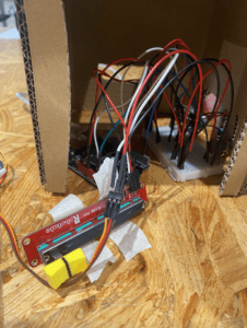
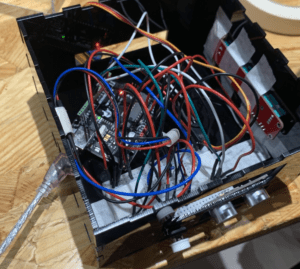
Final Circuitry:


Final code:

Arduino:

int buttonstate; //hold button state for food
int temperature = A1;
int food = 2;
int light = A0;
//below is variavles for distance sesnor
const int trigPin = 9;
const int echoPin = 10;
// defines variables
long duration;
int distance;
// servo setup
#include <Servo.h>
Servo myservo;
int pos = 0;
void setup() {
Serial.begin(9600);
pinMode(2, INPUT); //void set up for button
pinMode(light, INPUT); //void set up sliding potentiometer
 
// void set up for distance sensor
pinMode(trigPin, OUTPUT); // Sets the trigPin as an Output
pinMode(echoPin, INPUT); // Sets the echoPin as an Input
// set up for servo position
myservo.attach(8);
}
float sinAngle = 0.0;
void loop() {
// Code for reading food state
buttonstate = digitalRead(food);
//Serial.print(“button:”);
//Serial.println(buttonstate);
//delay(1);
 
// Code for reading temperature state
int sensorValue = analogRead(temperature);
//Serial.print(“meter:”);
//Serial.println(sensorValue);
//delay(1);
 
// Code for reading Light states
int value_slide_pot_a = analogRead(light);
//Serial.print(“Slide Pot value: “);
//Serial.println(value_slide_pot_a);
//delay(1);
 
//code for reading distance
// Clears the trigPin
digitalWrite(trigPin, LOW);
delayMicroseconds(2);
// Sets the trigPin on HIGH state for 10 micro seconds
digitalWrite(trigPin, HIGH);
delayMicroseconds(10);
digitalWrite(trigPin, LOW);
// Reads the echoPin, returns the sound wave travel time in microseconds
duration = pulseIn(echoPin, HIGH);
// Calculating the distance
distance = duration * 0.034 / 2;
// Prints the distance on the Serial Monitor
//Serial.print(“Distance: “);
//Serial.println(distance);
// max distance is 557
Serial.print(buttonstate);
Serial.print(“,”); // put comma between sensor values
Serial.print(sensorValue);
Serial.print(“,”);
Serial.print(value_slide_pot_a);
Serial.println();
if(distance <= 200 && distance >= 20){
sinAngle = sinAngle + 0.02;
/*
for (pos = 0; pos <= 20; pos += 1) { // goes from 0 degrees to 20 degrees
// in steps of 1 degree
myservo.write(pos); // tell servo to go to position in variable ‘pos’
delay(30); // waits 15 ms for the servo to reach the position
}
for (pos = 20; pos >= 0; pos -= 1) { // goes from 20 degrees to 0 degrees
myservo.write(pos); // tell servo to go to position in variable ‘pos’
delay(30); // waits 15 ms for the servo to reach the position
}
*/
}elseif(distance < 20){
sinAngle = sinAngle + 0.1;
/*
for (pos = 0; pos <= 35; pos += 1) { // goes from 0 degrees to 35 degrees
// in steps of 1 degree
myservo.write(pos); // tell servo to go to position in variable ‘pos’
delay(10); // waits 10 ms for the servo to reach the position
}
for (pos = 35; pos >= 0; pos -= 1) { // goes from 35 degrees to 0 degrees
myservo.write(pos); // tell servo to go to position in variable ‘pos’
delay(10); // waits 10 ms for the servo to reach the position
}
*/
}else{
sinAngle = sinAngle + 0.01;
/*
for (pos = 0; pos <= 10; pos += 1) { // goes from 0 degrees to 10 degrees
// in steps of 1 degree
myservo.write(pos); // tell servo to go to position in variable ‘pos’
delay(100); // waits 15 ms for the servo to reach the position
}
for (pos = 10; pos >= 0; pos -= 1) { // goes from 10 degrees to 0 degrees
myservo.write(pos); // tell servo to go to position in variable ‘pos’
delay(100); // waits 20 ms for the servo to reach the position
}
*/
}
int servoAngle = (int)(90.0 + sin(sinAngle) * 30.0);
myservo.write(servoAngle);
//Serial.println(servoAngle);
delay(10);
}
 

Processing:

//import arduino values
import processing.serial.*;
Serial serialPort;

int NUM_OF_VALUES_FROM_ARDUINO = 3; /* CHANGE THIS ACCORDING TO YOUR PROJECT */

/* This array stores values from Arduino */
int arduino_values[] = new int[NUM_OF_VALUES_FROM_ARDUINO];

//capture webcam footage
import processing.video.*;
String[] cameras = Capture.list();
Capture cam;

// insert sound
import processing.sound.*;
SoundFile yummy;
SoundFile hot;
SoundFile cold;

//importing images of food
PImage photo;
PImage img;

//food bouncing array
int numFood = 10;
float [] triXs = new float [numFood];
float [] triYs = new float [numFood];
float [] speedXs = new float [numFood];
float [] speedYs = new float [numFood];

void setup() {
size(640, 480);
background(0);

cam = new Capture(this, cameras[0]);
cam.start();

for (int i=0; i<numFood; i=i+1) {
triXs[i] = random(0,640);
triYs[i] = random(0,480);
speedXs[i] = random(-7,7);
speedYs[i] = random(-7,7);
}
photo = loadImage(“burger.png”);
img = loadImage(“eyehole.png”);
printArray(Serial.list());
// put the name of the serial port your Arduino is connected
// to in the line below – this should be the same as you’re
// using in the “Port” menu in the Arduino IDE
serialPort = new Serial(this, “/dev/cu.usbmodem11201”, 9600);

yummy = new SoundFile(this, “yummy.wav”);
hot = new SoundFile(this, “hot.wav”);
cold = new SoundFile(this, “Brrr.mp3”);
}

void draw() {
background(0);

//trying to rotate
//translate(width/2, height/2);
//rotate(radians(-180));

pushMatrix();
translate(cam.width,0);
scale(-1,1); // You had it right!
image(cam,0,0);
popMatrix();

// receive the values from Arduino
getSerialData();

if (cam.available()) {
cam.read();
}
//change color of footage

tint(map(arduino_values[2],1023,0,100,255), map(arduino_values[2], 0, 1023, 100, 255), map(arduino_values[2], 0, 1023, 100, 255), 255);
//image(cam, 0, 0);

if (arduino_values[2] == 0) {
if (hot.isPlaying() == false) {
// start playing it
hot.play();
}
}
if (arduino_values[2] == 1023) {
if (cold.isPlaying() == false) {
// start playing it
cold.play();
}
}

//bouncing burgers
if (arduino_values[0] == 1 ) {

// if the sound is not already playing
if (yummy.isPlaying() == false) {
// start playing it
yummy.play();
}
for (int i=0; i<numFood; i=i+1) {
image(photo, triXs[i],triYs[i],photo.width/3,photo.height/3);
triXs[i] = triXs[i] + speedXs[i];
triYs[i] = triYs[i] + speedYs[i];

if(triXs[i] > 580 || triXs[i] < 0) {
speedXs[i]=-speedXs[i];
} if (triYs[i] > 400 || triYs[i] < 0) {
speedYs[i]=-speedYs[i];
}
}
}
image(img, 0,0,640,480);

println(arduino_values[0]);
println(arduino_values[1]);
println(arduino_values[2]);

}

// the helper function below receives the values from Arduino
// in the “arduino_values” array from a connected Arduino
// running the “serial_AtoP_arduino” sketch
// (You won’t need to change this code.)

void getSerialData() {
while (serialPort.available() > 0) {
String in = serialPort.readStringUntil( 10 ); // 10 = ‘\n’ Linefeed in ASCII
if (in != null) {
print(“From Arduino: ” + in);
String[] serialInArray = split(trim(in), “,”);
if (serialInArray.length == NUM_OF_VALUES_FROM_ARDUINO) {
for (int i=0; i<serialInArray.length; i++) {
arduino_values[i] = int(serialInArray[i]);
}
}
}
}
}

Conclusion

The goal of this project was to make an interactive pet alien. I would say that I was moderately successful with this plan. While people seemed to have issue with the presentation causing some confusion on interaction purpose, I think users were able to understand the concept well.  Though some people were confused on exactly what the purpose of each switch was, people were drawn into the buttons and sliding potentiometer and were excited to continue pressing buttons and sliding the potentiometer to make the alien speak and make noise. People seemed to inherently understand that the burgers appearing meant that the alien was being fed. People also seemed to enjoy messing with the distance sensor by getting closer and farther from the alien. Every aspect of possible interaction was explored by all who tested it. I believe it fits my idea of interaction cause people were able to continue to have a conversation with the alien through changing multiple stimuli. Some improvements for the project are 3 things: one with the code being a hunger bar in order to give a reason for feeding it to make it more interactive. Anther interaction would be screen presentation. Instead of placing the computer behind the project, a different monitored that was less intrusive could be added behind. A final improvement would be to label the buttons and switches for a clearer presentation. From my setbacks I was able to learn “when to quit.” This meant that when. something seemed impossible, finding an easier solution to create a similar effect can be an important tool to move on. From my accomplishments I have been able to learn that I am able to create some very  polished looking work using digital fabrication. 

This project has let me explorer and increase my affinity to breathing life into machines. This project was sucsessfully able to demostrate interactions with creatures unknown using our senses of sound and sight without specifically using words.
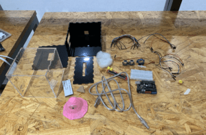
Disassembly

Appendix

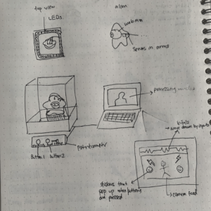
Original sketch by me of project

Citations:

Alien sound chirp:

https://www.soundsnap.com/monster_element_alien_creature_chirp_02_sfxbible_ss00232


Ho yeah:

https://www.soundsnap.com/who_yeah_long_wav


Brrrrr:

https://www.youtube.com/watch?v=qycVSRGghzo


Eye hole:

https://www.clipartmax.com/download/m2i8A0N4H7i8H7d3_base-eye-pov-read-it-and-weep-safe-simple-background-circle/


The Environment Monster – Vilius Schmidt – Gottfried Haider

Context and Significance

The interactive art project “The Environment Monster” was inspired by my previous project “Barbie AI.” While “Barbie AI” has no electrical components, the project’s performance demonstrated interactivity that was fundamental to the approach taken in “The Environment Monster.” When researching for, and performing “Barbie AI,” I defined interactivity as “Your action on the artifact should generate a response that in turn you can react back to.” While in “Barbie AI” which took the form of a complex closet that algorithmically selects your clothes and dynamically reads your responses, with “The Environment Monster” a more simple approach was taken to fit the limitation of the Arduino kit. In this case, research on things like toys was more helpful. One toy that became the backbone for “The Environment Monster’s” development was “Tickle Me Elmo.” First introduced to me as a meme, when then Elmo is touched on its stomach, it laughs, swinging its arms and making noise. Later I saw a video of a Tickle Me Elmos that was skinned of its kind face and red fur, the laughing metal skeleton was quite menacing and horrible instead of child-friendly. This is the idea of interactivity that interested me. How do people interact, and continue to interact with something unpleasant or accusatory? This idea birthed “The Environment Monster,” whose wrath punishes you for messing with the natural environment. The target audience for this project in my eyes would be a general adult audience. While maybe not that incautiously curious as children, I believe the message is most important to those adults who have a much greater impact on the environment. Our greed and obsessiveness over the resources of nature should not go unpunished. 

Conception and Design 

In “The Environment Monster,” Both the monster and the environment were physical objects. However, the objects that could receive reactions to be processed by the monster were specific objects in the environment. To welcome the user into touching things in the environment, and for them to touch the proper thing, the things in the environment were made the stand out. Thus, every physical object in the enclosure exhibits a response from the monster when touched. Using capacity touch sensors, the fish and the tree in the atrium naturally stand out being the only objects with a coppery metallic look, thus differentiating them from everything else. However, this did not work for the trash can as well. In the critique of the project, not everyone understood that the trashcan was a moveable and intractable object like the tree and the fish. 

 vs.

Another design choice was making everything out of paper and cardboard. As a light, stable, and malleable material, the environment (from the backdrops to the intractable objects ) was easily able to be created in a simple manner. As none of the interactions facilitated a heavy hand, more study materials were not needed. With more time and skill, however, I would have preferred the monster to not be made out of cardboard and paper cups. While easy to build with and paint on, I found its design quite unappealing, and unable to instill a fear befitting of a monster. Modeling clay was one alternative idea, however was not befitting the necessity to attach the monster with motors. Perhaps the better method would be to 3D print the monster, where more detail could be expressed while also having the customizability to rig move parts. the reason 3D printing was not used was for the time constraint on this project. 

Fabrication and Production

Crafting the Concept: The first challenge that arose in creating the project was defining a concept for the project. I started with an idea of a monster that you could “bother,” in which, using a variety of sensors, the monster would get mad if it was touched, petted, or even if a light was flashed in its eyes. This idea was morphed into a security bot, which could be set off in the same way the “bother it” monster would have been. However, its lack of message, and complex sensor interactions it would require made it impractical. Thus “The Environment Monster” was born. Taking inspiration from both the previous ideas, this monster would become progressively angrier the more the environment was messed with, in which pieces of the environment would be switches that would affect his LED eyes and arms to express his mood. 

Building the Monster Prototype: With the idea of not involving an environment, multiple objects needed to be physically interacted with. With the help of Gottfried, I selected capacitive touch sensors as environmental triggers for the monster. First using example code for digital read, I tested the capacitive to make sure that when pressed its value would read “1” and when not touched its value would be “0”. A piezoelectric sensor was then tested using an analog read function to test its values. a light yet significant tap gave a read of a value over “100.” With this, the capacitive touch sensor and the piezoelectric sensor were placed in a breadboard and connected to a digital pin and an analog pin together, and a code using a conditional was created so that action would occur if either the capacitive touch sensor or the piezoelectric sensor were activated. 

code:

int pushbutton = 9;
int vibrate = A0;
void setup() {
//Put your setup code here, to run once:
Serial.begin(9600);
pinMode(pushbutton,INPUT);
}
void loop() {
 
int buttonstate = digitalRead(pushbutton);
int sensorValue = analogRead(vibrate);
if(sensorValue > 100 || buttonstate == 1){
Serial.println(“roar”);
delay(100);
}
}
The idea was that if the monster was vibrated, or an object in the environment was touched, the monster would become angry and go “roar”. As “roar” was not the response I was looking for, I then was cued into Smart LEDs a a way to express the monster mood using color-changing eyes by Gottfried. Since a basic coding prototype had successfully determined the viability of the sensors, I then worked on coding more complex reactions for the monster. To show the monster becoming progressively more angry, I tried to incorporate states into the code. So that each time the sensors were disturbed, it would go to its next stage of anger, starting happy with green eyes, then going to yellow eyes, and then finally to red mad eyes. However, multiple complications arose at this step, as the monster would cycle through these steps and flip between them without prompt. Using both delay functions to stop the monster from transiting states too fast, and using code to detect the pressing and un-pressing of a button did not fully remedy the unreliability. Thus a different avenue was approached. Using the help of Gottfried, using variables, a conditional was set that when the capacitive sensor was touched on, an “angriness” value would increase, and when a certain threshold was reached it would have a max angriness of “1.00”. The LED eye color would then dynamically change with the “angriness” value. This is the effect that was used to continue with the project. The piezoelectric sensor was ditched. After the wiring for a second capacitive touch sensor was added so that a fish and a tree would become intractable objects in the environment, a servo motor was added to the Arduino. The servo motor was coded to stay still when the angriness was under 1.00 angriness, but when max angriness was reached, the servo would sweep to simulate anger. I then built the environment out of cardboard and cut out details for the monster’s face. I also saudered the capacitive touch sensors to a cardboard cutout of a fish and a tree that had copper tape on them to complete the interactive elements. Finally, I attached the glowing eyes and the sweeping arm. 
 
 
Finishing the Monster: Helpful ideas for improvement came about in user testing. The ones that I decided to take were adding noise to the monsters anger, decorating the diorama, and to add more intractable objects. First using a loud single tone buzzer, I made the monster beep on and off once the condition was met for max anger. for the adding of more intractable objects, a magnet sensor was added, and a new conditional and variable was created for “happiness” so that when the magnet sensor was not detect a magnet, the monster would be happy. I then created a condition for max happiness in which the servo would gently wave when reaching max happiness, and also included in the LED function so that the eyes would change dynamically to blue when happiness increases. Finally I worked with my group to decorate the diorama. 
 
Final Code:
int tree = 9;
int fish = 12;
int treestate;
float angriness = 0.0;
float happiness = 0.0;
const int buzzerPin = 5;
int SENSOR_PIN = 2;
int sensorVal;
#include <Servo.h>
Servo myservo;
int pos = 0;
#include <FastLED.h>
#define NUM_LEDS 60 // How many leds on your strip?
#define DATA_PIN 3
CRGB leds[NUM_LEDS];
void setup() {
// put your setup code here, to run once:
Serial.begin(9600);
pinMode(tree, INPUT);
pinMode(fish, INPUT);
FastLED.addLeds<NEOPIXEL, DATA_PIN>(leds, NUM_LEDS);
FastLED.setBrightness(50);
myservo.attach(8);
pinMode(SENSOR_PIN, INPUT);
}
void loop() {
treestate = digitalRead(tree);
int fishstate = digitalRead(fish);
sensorVal = digitalRead(SENSOR_PIN);
Serial.print(“Button: “);
Serial.println(sensorVal);
if(treestate == 1 || fishstate == 1){
// making me angry
angriness = angriness + 0.05;
if(angriness > 1.0){
angriness = 1.0;
tone(buzzerPin, 200, 500);
delay(100);
for(pos = 0; pos <= 90; pos += 1){ // goes from 0 degrees to 180 degrees
// in steps of 1 degree
myservo.write(pos); // tell servo to go to position in variable ‘pos’
delay(3); // waits 15 ms for the servo to reach the position
}
for(pos = 90; pos >= 0; pos -= 1){ // goes from 180 degrees to 0 degrees
myservo.write(pos); // tell servo to go to position in variable ‘pos’
delay(3); // waits 15 ms for the servo to reach the position
}
}
}else{
angriness = angriness – 0.01;
if(angriness < 0.0){
angriness = 0.0;
}
}
**code inspired by Gottfried Haider
if(sensorVal == 0){
// making me happy
happiness = happiness + 0.03;
if(happiness > 1.0){
happiness = 1.0;
for(pos = 0; pos <= 45; pos += 1){ // goes from 0 degrees to 180 degrees
// in steps of 1 degree
myservo.write(pos); // tell servo to go to position in variable ‘pos’
delay(15); // waits 15 ms for the servo to reach the position
}
for(pos = 45; pos >= 0; pos -= 1){ // goes from 180 degrees to 0 degrees
myservo.write(pos); // tell servo to go to position in variable ‘pos’
delay(15); // waits 15 ms for the servo to reach the position
}
}
}else{
happiness = happiness – 0.07;
if(happiness < 0.0){
happiness = 0.0;
 
}
}
 
// XXX: look into .lerp8()
leds[0] = CRGB(255 – (happiness * 255), 255 – (angriness * 255), 255 – (angriness * 255));
leds[2] = CRGB(255 – (happiness * 255), 255 – (angriness * 255), 255 – (angriness * 255));
FastLED.show();

**Code inspired my Gottfried Haider

//Serial.print(“Angry: “);
//Serial.println(angriness);
Serial.print(“Happy:”);
Serial.println(happiness);
delay(50);
}
Conclusion
The goal of this project was to make a monster that acts as a voice for the environment. When you mess with the environment, the monster will get mad, however if you help the environment the monster will be happy. This art piece is supposed to make us think our own relationship to the effect we have on the environment. I think the project aligns well with my definition of interactivity. There are multiple different ways you can initially act on the piece, and the monster is able to act back in different way according to your actions. The monsters actions themselves also affect how me may continue to react to the piece. I think that the project is not perfect with interactivity. It can easily be “outsmarted” due to not being able to integrate multiple responses. However, I think the project was successful, as testers, without much promoting had expected interactions with out project. If I was to have more time I would work on tweaking the set design in order to more easily foster interaction, as well as integrate responses. In this process I have learned a lot about the logic of coding, as well as the truly difficult task of producing an interaction from your own imagination. 
 

Idea of security monster


Group Research Project: BarbieAI

Formulating an Idea

As per the directions for the Interaction Lab group project, when creating the BarbieAI, the artifact had to be a completely non-mechanical artifact that through performance and prop work would allude to an interactive object based on one of 3 dystopian short stories. To determine what the artifact would be, a group brainstorming session occurred where every group member shared their best ideas that were previously created in the “Reading” part of the group project assignment. The reading portion involved all group members to come up with an invention that could exist in the fictional world of “The Veldt” by Ray Bradbury, “The Ones Who Walk Away from Omelas” by  Ursula K. Le Guin, and “The Plague” by Yan Leisheng. In the end, a combination of ideas (a Barbie dream house inspired by the Happylife home from “The Veldt”, and a conflict resolution mediating machine also inspired by “The Veldt”) were turned into a “Barbie” closet that could automatically choose your outfits. 

Before designing the artifact, we answered questions that helped us figure how the artifact was to be used and how it would interactive. This can be seen in the link below.  

BarbieAI_Brainstorm

While none of my ideas were selected when deciding what our artifact should be. I was an avid participator in coming up with these “guiding questions”, as well as brainstorming answers to these questions. My contributions along with the contributions of every other group member gave us a clear views of the artifact we would create. 

Building BarbieAI

The final idea for BarbieAI is an interactive closet that senses your body biometrics, mood, and outside weather using a mixture of visual and temperature sensors to determine a “perfect” outfit based on current fashion trends. The closet then generates these clothes to be worn.

Using a cardboard box that was cut into the shape of a bent poster board as a base, plastic poster board was painted pink and hot glued to each side of the box to make a rhomboidal front facing structure. Then the closet was decorated to add extra detail. After the team collaborated on deciding the shape of the closet, I took the main role in building it. Cutting out the pink panels and gluing them to the cardboard base, decorating the closet with clouds, adding the barbie logo, and drawing on the side details were all done by me and the help of a rotating cast of my other teammates. 

the overall shape is reminiscent of a changing stall and thus was not too difficult to make and stay together. The most difficult part was creating a “Barbie” pink color to pain the closet, and then cutting out the panels to attach them to the cardboard base. A pleasant surprise was that the the closet was quite sturdy and had no problems standing on its own, and stayed together strong when being transported. 

Video of performance is embedded below:

I think the performance was successful in delivering information on how the product was interactive, as well as exploring some social impact that would be involved in the invention of such an artifact as the BarbieAI. However, I think that came at the cost of making our presentation truly a great narrative. Much of the dialogue could be strewn to be almost advertisement-like. In possible further iterations I believe that a more subtlety approach would improve the project. I also believe that including more of the social problems that we had discussed possible with this artifact into our presentation would have made our presentation stronger. However I believe, terms of explaining its interactivity based on my definition of interaction, the performance was very successful. My definition of interaction is that both parties are able to receive stimulus from the other and process in into a reaction. The human inputs their tastes and emotions and the machine is able to make a physical object out of that action, and then the human can react to the physical object letting the closet to continue to react. 

Overall the group got a long quite well, and everyone in the group was able to contribute to an aspect of its success. There was no storming phase and pretty immediately we were working productively as a team. This was especially the case in the brainstorming phase. Everyone was present during the building of the object. And although lopsided, everyone has a role in the performances. I would say this is a success considering the group had 7 people.  

The Mirror

Another groups performance I particularly enjoyed was Groups E’s “The Mirror”. I think it is so successful for 3 reasons. One, their artifact was directly based in the world of on of the short stories quite directly. Two, their artifact and performance directly look at the social ramifications of their object. The mirror is a conversation piece in the work of the story that reveals and commentates on the social ills of the fictional city of Omelas. The third reason I think it was successful is that all of that was conversed quite seamlessly in their performance and was not like an infomercial at all. 

One way they might not have been entirely successful is that I do not think the artifact was completely interactive. While the mirror could react to the stimulus of whoever was looking into it, a person could not continue a “conversation” with it, as its possible outcomes were quite simple (look into the mirror when you are happy? see the abused child. Look into the mirror sad? you will see nothing). However, I think it was clever because it seemed the purpose of the mirror was to foster interaction and conversation between the citizens of Omelas. 

End

This is the end of my blog post regarding the Interaction Lab group project. Thank you for reading

-Vilius Schmidt 9/27/2023


Hello world!

Welcome to Web Publishing @ NYU. This is your first post. Edit or delete it, then start creating your site!

Online help is available via the Web Publishing Knowledge Site (wp.nyu.edu/knowledge) and the ServiceLink knowledge base (www.nyu.edu/servicelink). Through ServiceLink, you can find step-by-step instructions, as well as tutorials.

Digital Accessibility

As content creators who create and publish text, images, video, and audio, you must adhere to the NYU Website Accessibility Policy (https://www.nyu.edu/digitalaccessibility/policy) when creating and publishing digital content.

Web Publishing-specific Digital Accessibility Best Practices and examples of how to ensure your content are compliant are available at https://wp.nyu.edu/digitalaccessibility

If you have additional questions, contact the IT Service Desk for assistance. Support is available 24/7/365. For more details, visit www.nyu.edu/it/servicedesk.