Task 1:
The purpose of this circuit is to make the buzzer ring upon clicking the button. Me and my partner Kenneth started off by studying the circuit diagram and understanding each component.
(Step 1) We initially encountered some difficulties with the button due to the fact that we didn’t know how the button was wired internally. The buzzer was constantly ringing when the wires are all connected, and the button wasn’t sending any outputs. Because of that, we decided to ask one of the learning assistants about how the button is wired, and we realize that we had to rotate the button in another direction for the button to send its output through.
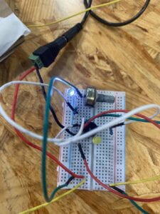
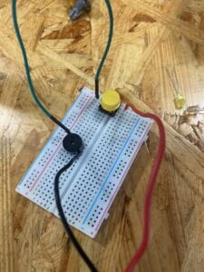 (Initial circuit)
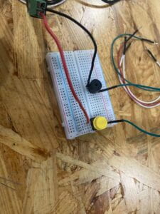 (Fixed circuit)
(Step 2) After completing step 1, we started to have a general idea of how the breadboard and circuits work. Although we didn’t encounter any difficulties, our breadboard was starting to look like a mess based on the way we wired each component. We’re starting to run out of space to place each component.
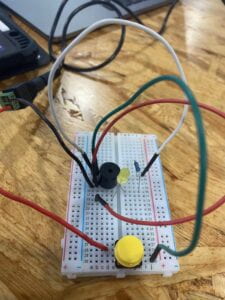
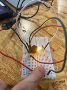
(Step 3) Me and my partner Kenneth were confused about the third circuit diagram, so we decided to ask the learning assistants for help again. We were then able to understand how the circuit is supposed to work with the new components. We were running out of space on the breadboard, so we had to rearrange our circuits. We found that some of the wires were unnecessary, so we started by removing those unnecessary wires and connecting the new circuit in a more efficient method.
Task 2:
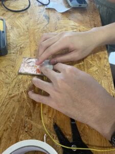
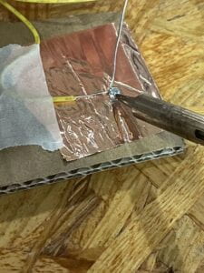
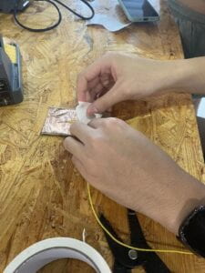
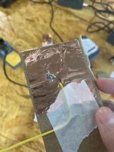
The purpose of task 2 is the create a DIY button using cardboard, wires, and copper tapes. We started by taping the copper over the top of a piece of cardboard so that it covers both sides of the cardboard. We tape a wire on the cardboard in a way that the tip of the wire is touching the copper tape. After that, we burnt one of the wires onto the copper tape and the taped wire so that it acts as a “glue” to both items. I learned that electric signals can be sent through the circuit by just allowing 2 good conductors of electricity to touch each other.
Task 3:
In task 3, me and my partner removed the button and replaced it with the DIY cardboard button instead. We put each end of the DIY button wire into the slot previously occupied by the button. We didn’t encounter any difficulties here since replacing a button with another button is relatively easy. Me and my partner used the word “Hello” as our morse code, and we paired up with another group for them to decipher our code. After some time, they were able to decode our morse code.
Additional Required Questions:
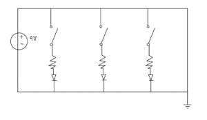
Question 1: The R1 resistor is placed so that the LED1 won’t receive an overflow of energy that could damage it. R1 resistor will only allow a certain amount of current to flow through to LED1. This way, LED1 won’t receive an exceeded amount of current flowing through it.
Question 2:
Question 3:
The circuits we built include interactivity because it measures our input from the button, which is listening to interactivity. Then it determines what our input means, which is thinking interactivity. After that, it flashes lights on the LED and rings the buzzer based on our input, which acts as speaking interactivity.
Question 4:
Interaction Design and Physical Computing can be a gateway to various new forms of art. Instead of the traditional art of drawing and painting, new technologies can be implemented so that humans can use other parts of the body to express craftsmanship. For example, a famous YouTuber called Mark Rober engineered a glitter bomb machine that’ll detonate glitter over a certain area once it’s removed from the box. This machine is created to take “revenge” on thieves who steal delivery packages in front of people’s homes.