EDM EXperience
Conception and Design
Initial Concept and Research
As my partner Jessica and I share a deep passion for EDM music, we were inspired to create an EDM soundboard to play around with the different stems of upbeat, electro music. Our vision is to craft a space for music, dance, and enjoyment, not confined to traditional rave or nightclub settings. Utilizing flex sensors, LEDs, a servo-powered turntable, and amps, we aimed to replicate the experience of a live DJ set with touchable elements. My preparatory research involved looking at the actual DJ equipment, and understanding what the different controllers are used for. I came across a website showcasing beginner DJ equipment with compelling design ideas and practical construction. From that, I decided to create a plate resembling a turntable, powered by a rotary encoder, capable of adjusting speed based on human touch. The research into beginner DJ equipment not only provided valuable insights into the aesthetic aspects of our project but also served as a practical guide for the design and construction phases. By examining the design inspirations and actual constructions found in the research, we gained a clearer understanding of the visual and structural elements that make a DJ setup appealing. Through this step, we also realized the limitations of what we can do– thus, we ended with 4 slide potentiometers, two turntables, and three buttons.
Design Decisions
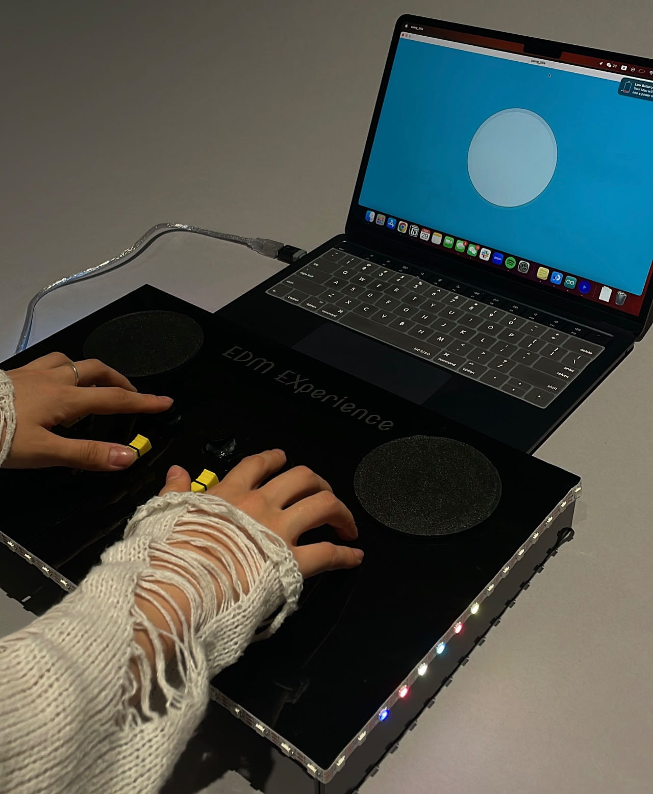
Our target audience included two distinct groups: those who are enthusiasts of clubbing and well-acquainted with EDM, and those who have minimal music interest and have never encountered EDM before. The user interaction is crafted to be unique and captivating, regardless of your musical background, you can create a distinct masterpiece of the song. But to make things clear, we laser cut labels and pasted them next to the different sensors, having “+” and “-” signs to indicate the direction of the turntables, and name labels for the rest of the sensors. The four different slide potentiometers allowed users to adjust stems (vocals/guitar/drums/backing), while pressing different buttons created “boom”, “tat”, and “tst” sounds. In terms of comfort and convenience, we strategically positioned the two turntables at the top. This decision not only mimics the layout of actual soundboards but also aligns well with the practicality of users controlling sensors located below the sound tables. The Neopixel LEDs also synchronized with the amplitude, enhancing the overall immersive experience.
User Testing
During the User Testing phase, our presentation included a functional prototype with two operating rotary encoders—one for volume control and the other for adjusting speed. While the three buttons for “boom, snare, kick” were also functional, there were issues with lagging and volume bugs. Our focus had primarily been on the rotary encoders, and we hadn’t programmed the slide potentiometers yet, leaving the hard components on our soundboard. The feedback was extensive, addressing existing components and suggesting different functionalities for the missing slide potentiometers.
Users noted that the button effects needed to be louder to match the song, and there was a concern about the volume function taking almost seven rotations to notice a significant increase or decrease. Consistency was an issue, with the snare never working, the kick occasionally lagging five seconds behind each press, and the hi-hat performing the best. The Neopixel LED strip malfunctioned due to code overloading, affecting the visual representation of amplitude analysis in processing.
While the overall construction and aesthetics were notable, there was a perceived lack of variety in the user experience. Professor Andy and other Learning Assistants suggested moving volume control from the rotary encoder to a slider and using the turntable to change the sound position, introducing an iconic “whacka-whacka” noise. They emphasized the essence of EDM lies in build-up and noisy electro music, proposing the use of amps for all sliders. Another student user requested different music tracks from different artists and expressed interest in having the sliders represent different stems of the songs.
Adaptations and New Design Decisions
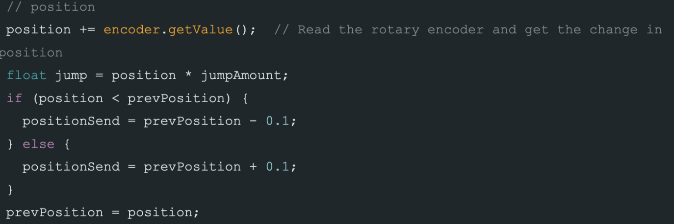
This session was extremely helpful to both Jess and I as we found out the audience’s needs and exactly what coding we needed to work on: we decided to debug the buttons, switch the volume rotary to a sound position rotary, attach the Neopixel and amplitude analysis code as a visual, and incorporated stems of a song into the different slide potentiometers. As the comments we got about the physical pieces were fine, we kept the soundboard design and fully worked on the code in Arduino and Processing alone. To debug the buttons, we scraped apart the hot glue and threw away the old wires, and reattached new ones to ensure that the hardwiring had no problems. In switching the volume rotary, I replaced the code with this: 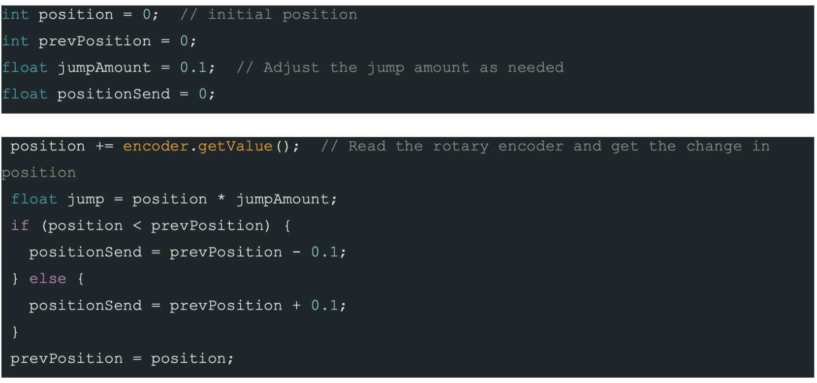
Essentially, determining the change in position, calculating a scaled jump value, and then adjusting the positionSend based on the direction of the change in position. Here, we also had to change the code in Processing to adjust sound position parameters based on the rotary encoder data:
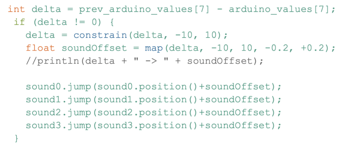 For the slide potentiometers, we collectively decided on using 4 stems (vocals, guitar, drums, backing) for the entirety of the song, and wanted them to be volume-based. Essentially, when they were at the maximum value, the individual stems would be playing at maximum volume, and when you turned it to its minimum, there would be no sound. In Arduino, we declared them as analog values; in Processing, we applied all volume and speed applicable to the individual tracks (or stems). To ensure that the mapping of the rotary encoders also applied to ALL 4 stems, we had to repeat the code for each aspect (amplitude, volume). Lastly, for the visualization factor, we went through line by line in the recitation code, making sure that all of our concepts were stated and declared correctly. Our debugging worked – and it ended up being that one of the analog values didn’t match up and serial data had some values missing.
Fabrication and Production
Production Process
In my production process, I’d like to highlight 4 major steps that finally led to the completion of a successful EDM experience. I’d also like to preface with an enormous emphasis on the coding aspect– our physical mechanism made up only 20% of our final project, and the coding accounted for nearly 80% as it was entirely sound-based.
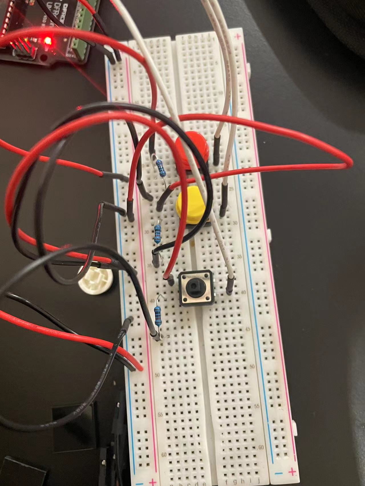
In our first stage, we experimented with the easiest sensor– push-button sensor – and attempted to switch the keypressed into actual Arduino coding. Here, it was rather simple to replicate Processing to Arduino, as I followed the sample and adjusted the pin numbers. However, we ran into several problems with hardwiring, as the hot glue wasn’t reliable and the buttons legs fell out of the connecting F/M wire. Hence, our middle button for User Testing was malfunctioning due to the hardwiring inconsistency.
The second stage was handling the rotary encoders. As I wasn’t fluent with the coding at all, I looked at sample codes controlling an LED strip, understood the different pins, and attempted to write one that controlled volume. I borrowed some lines from Processing, and by the night before User Testing, the volume controls had worked. Speed however, was a pain. The mapping was not the same as Volume, had completely different parameters, and everytime I uploaded the code, there would be different NullPointerExceptions. As the hardwiring for the buttons and coding for the rotary encoder took up the majority of the time prior to User Testing, we only presented the 5 working components, and left out the 4 sliders.
(User Testing)
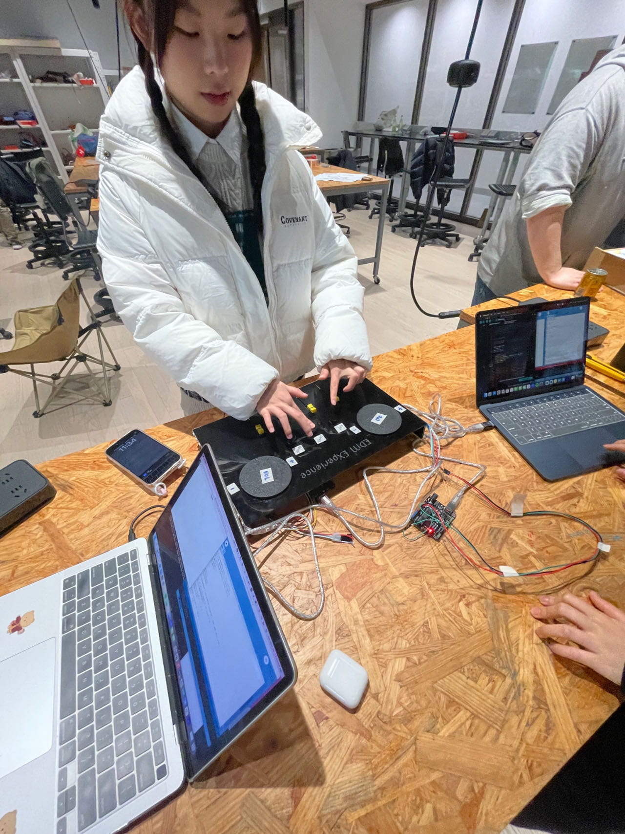
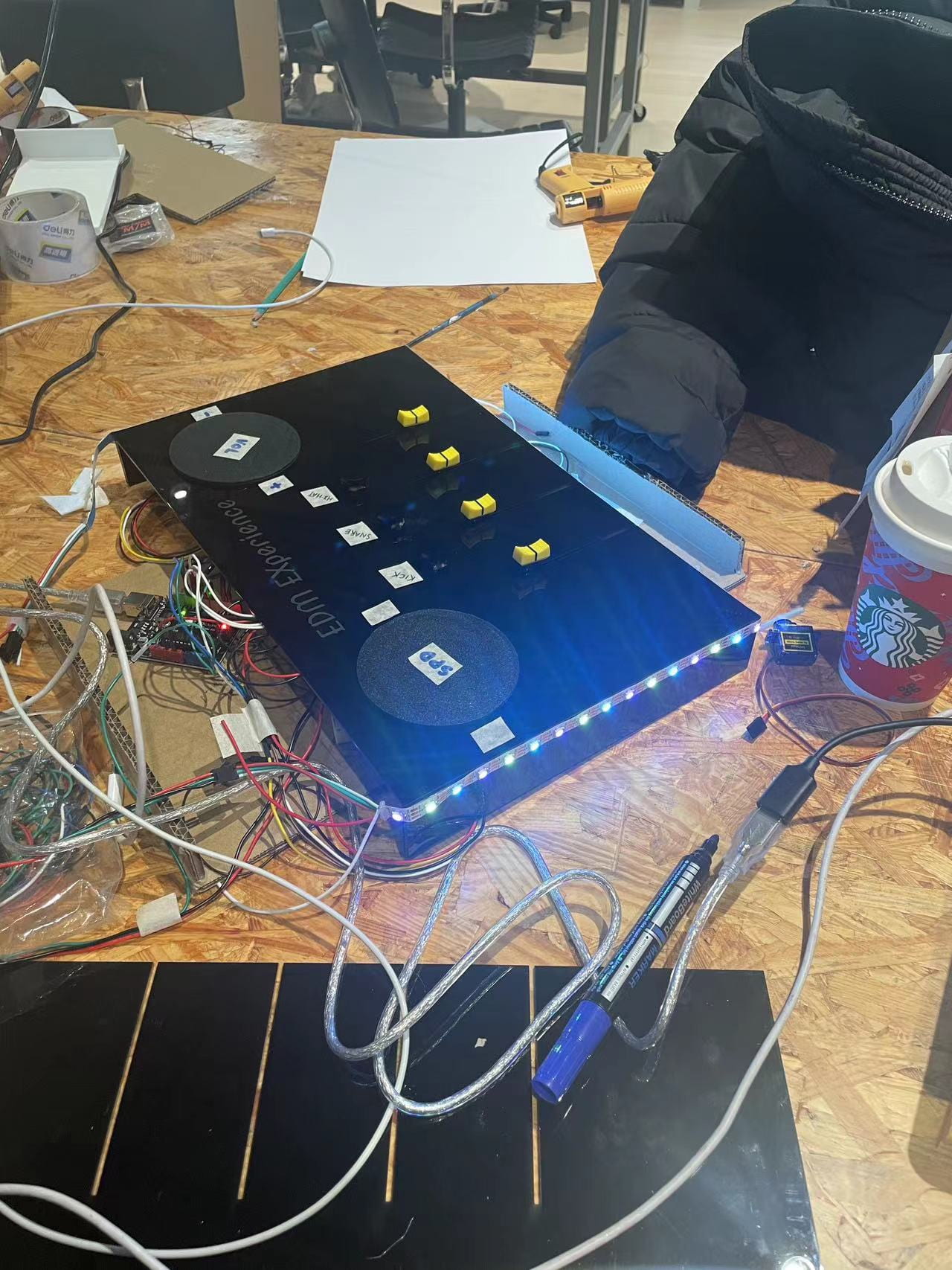
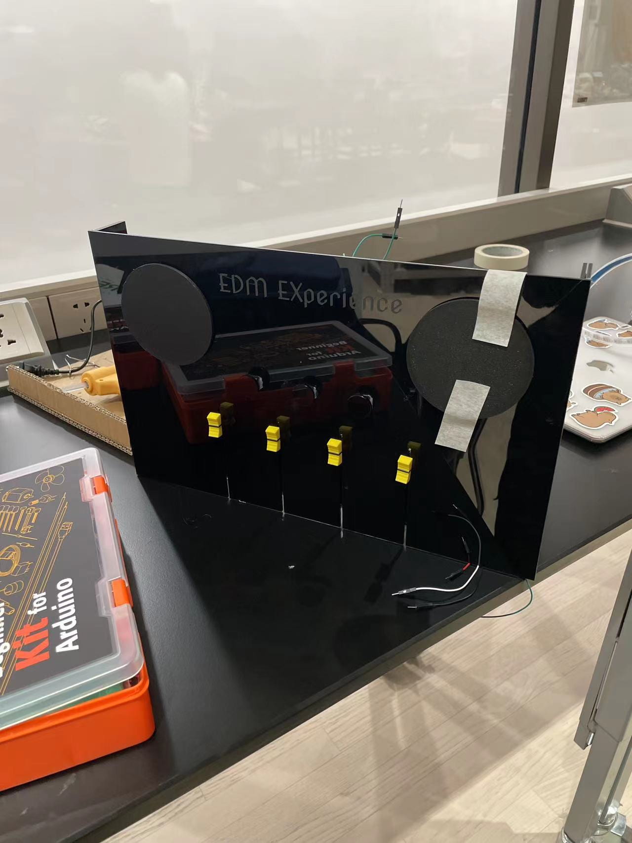
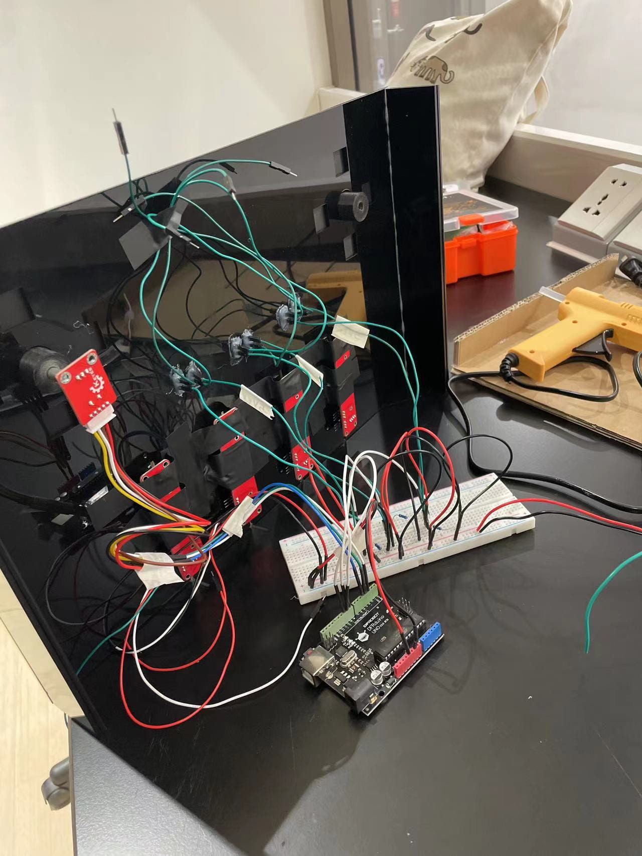
In the third stage, Jess and I had gathered feedback from User Testing, and were focusing on making the pre existing sensors better and debugging. We first detached all button sensors, replaced them with new ones, replaced the F/M wires as well, and reglued them through the soundboard. Following Kevin’s advice, we also edited the soundfiles to be shorter, more cohesive with our soundtrack, and solved the problem of the occasional lagging and malfunctioning. I then spent the rest of the time switching the volume rotary encoder to one that controlled the position of the soundtrack. We aspired to achieve the “wackawacka” sound effect, but once again, the parameters of the Arduino Code and mapping of the Processing never worked. I reached out to the Professor for help, and our end code ended up being:
(Arduino – position)
(Processing – position)
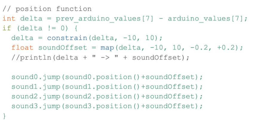
Essentially, the rotary encoder would read the input, calculate a position change, and determine a new position value based on certain conditions.
Our last stage was figuring out how to assign different stems to the individual slide potentiometers, and altogether have the speed and position rotary control all of those simultaneously. To do so, we already had the mapped speed and position, and pasted the four sounds below. In short, we repeated all of the stems underneath play, amp, position, volume, and they worked successfully. Our last sensor was the Neopixel LED that always malfunctioned when the code was put together. This time, we went through line-by-line ensuring that all the digital and analog pins were accurately declared, mapping was declared, and everything was in the right notation. Our project ended up successful despite the rough coding, having bright LEDs with the amplitude analysis, slide potentiometers for stem control, push-buttons sensors for added-on percussion, and rotary encoders for speed and position(time) parameters.
Sensors, Actuators, other Elements
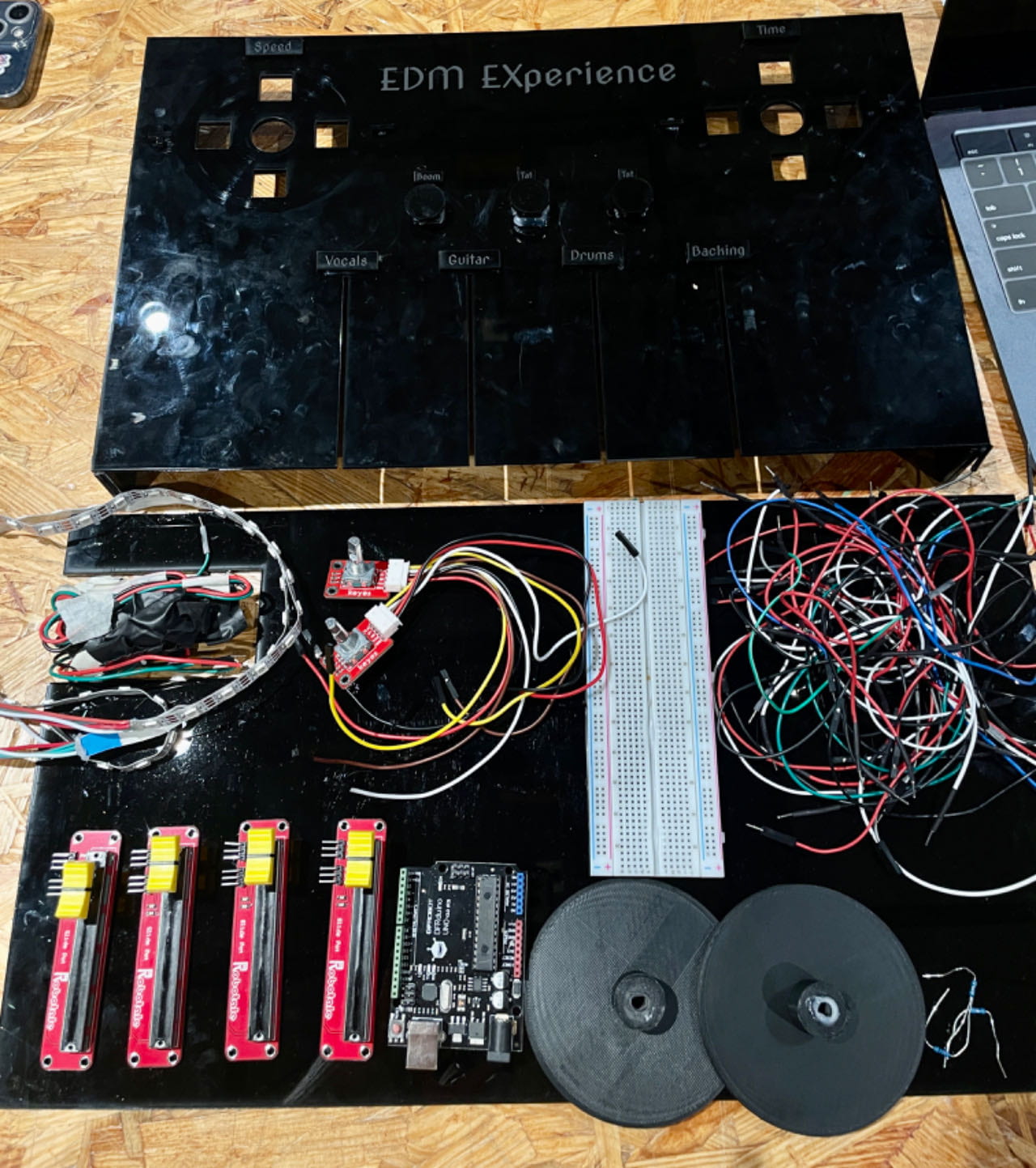
For this project, our sensor selection included push-button sensors, slide potentiometers, rotary encoders, and a Neopixel LED strip. During class experiments with processing sound files, I was particularly inspired by the “triggering_multiple_sounds” technique, where keys produced basic percussion noises. Recognizing the engagement and appeal of this interaction, I envisioned implementing a similar concept using buttons in Processing. Given the project guidelines restricting the use of keys or mouse presses, I found buttons to be the most convenient, and universally-understood alternative. They offered simplicity in wiring and debugging compared to more complex sensors like flex sensors. I kept user perception as a priority, as individuals are always inclined to press on things, and would not know what to do when they see a flex sensor.
The choice of slide potentiometers was evident from the project’s concept when we decided to create an EDM soundboard. The visual and technical association of slide potentiometers with traditional DJ machines, characterized by rows of sliding buttons, made them the most ideal fit for our project.
The incorporation of rotary encoders was suggested during office hours by Prof Andy when considering the operation of turntables. While my initial thought was to use servo motors, I did further research that led me to explore various motor options. The challenge was to achieve infinite spinning dependent solely on user actions. The rotary encoder emerged as the optimal choice due to its precise rotation detection—a critical factor for controlling parameters like speed, pitch, and position. Additionally, the rotary encoder supports rotation sensing in both clockwise and counterclockwise directions, allowing us to implement different speed and time codes. Unlike potentiometers or sliders, the rotary encoder offers infinite rotation with no start/stop limits, providing the best turntable-like functionality.
Neopixel LEDs were added to enhance the overall EDM DJ setup, and I was inspired by yet another processing recitation. I actually used an EDM song, as the amplitude analysis matched extremely well with the build-up of drums/bass/backing.
(Sensors)
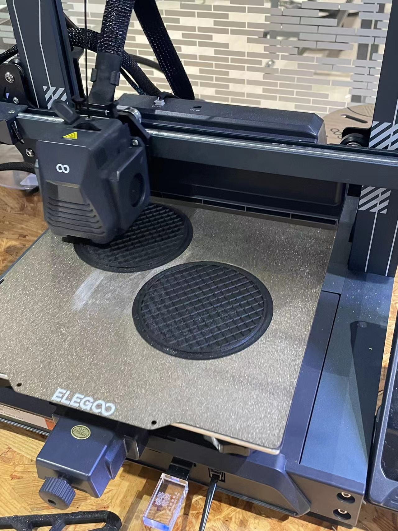
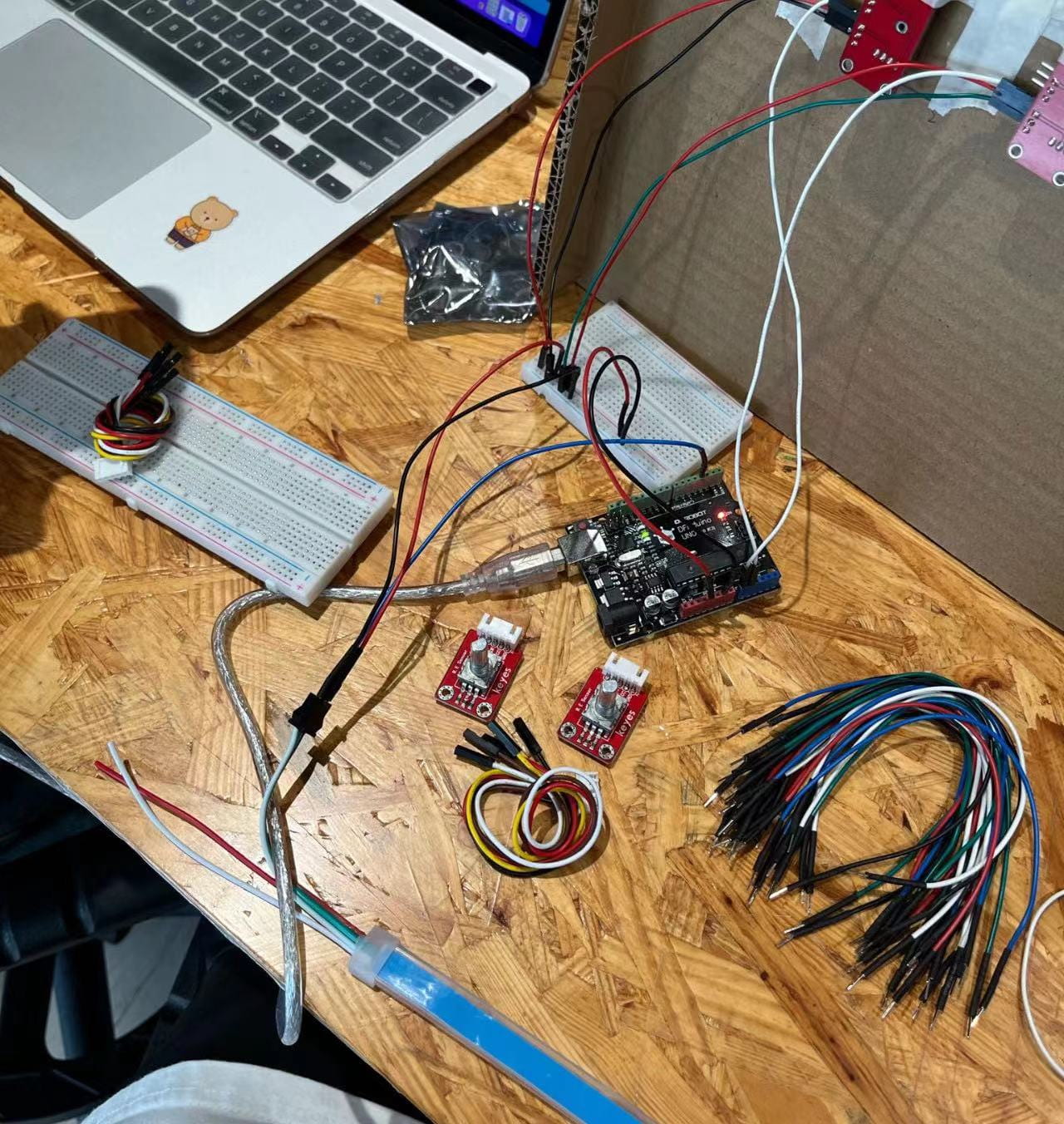
(3 Ideas Brainstorming- Sketch)
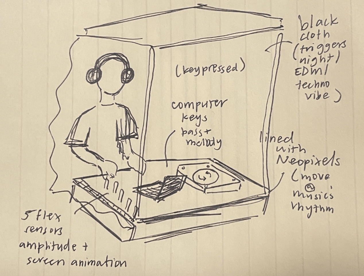
(Project Proposal- Sketch)
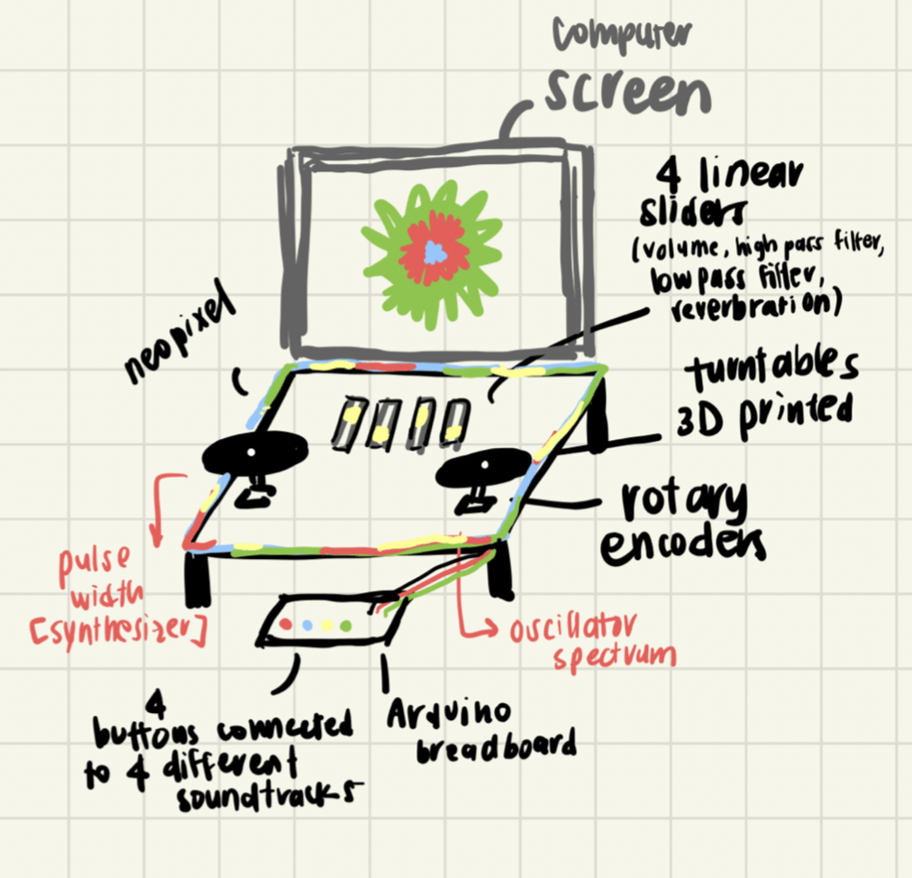
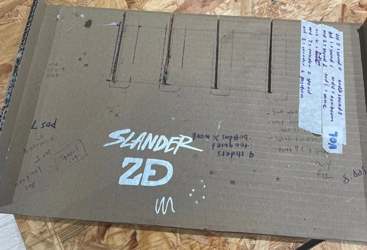
(Cardboard Prototyping- Sketch)
Conclusions
(Final Video- IMA Show)
Goals and Audience Interaction
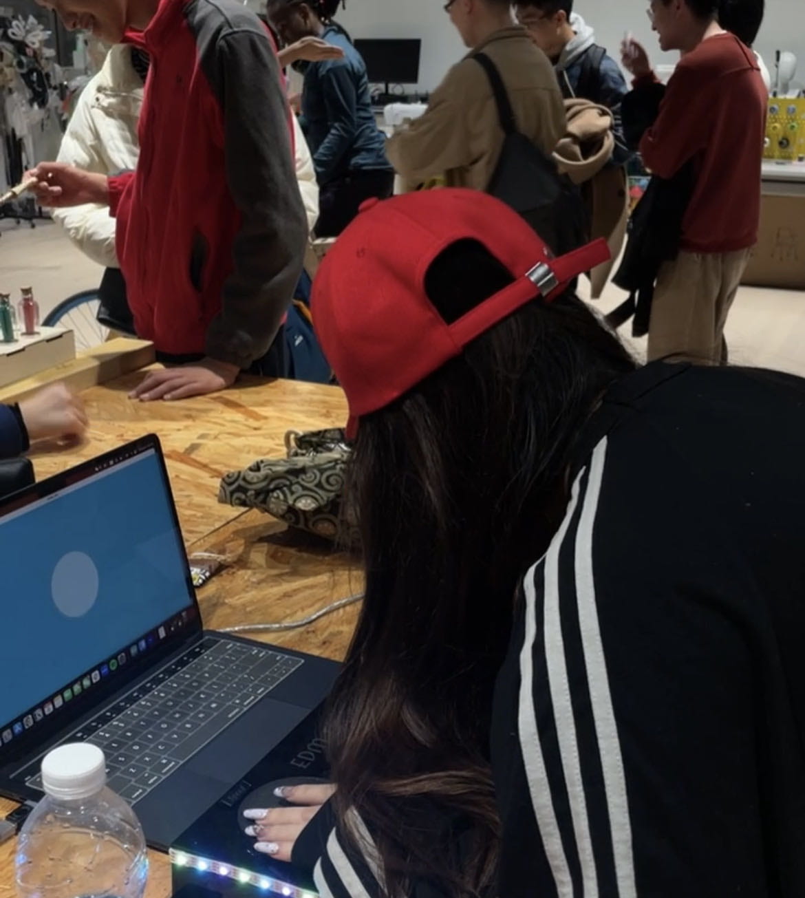
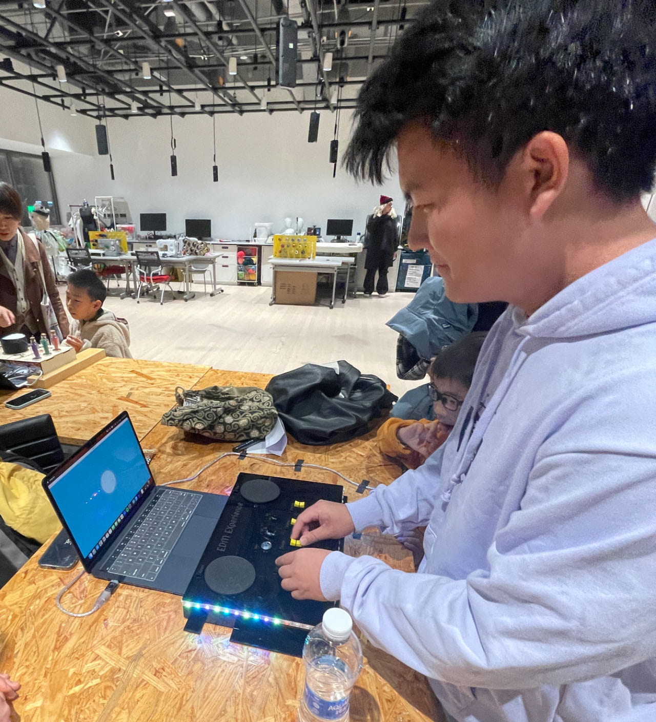
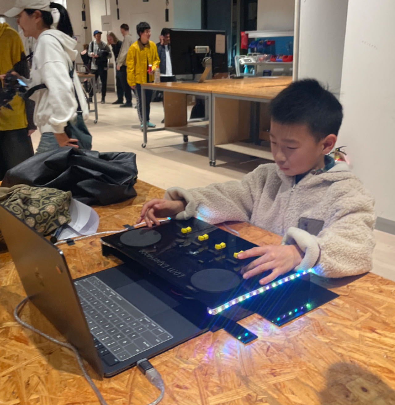
The objective of this project was to create a unique masterpiece of an electro song, utilizing a range of sensors and slide potentiometers to modulate the speed, key, percussion, and stems of the music. We designed this experience to establish a vibrant space for music, dance, and overall enjoyment. Our project definitely achieved its stated goals– and also appealed to users of all music expertise! During the IMA show, we witnessed the broad appeal of our creation. We had several child DJs enthusiastically manipulating the speed, reveling in the fast-paced, squeaking noises, and then abruptly transitioning to the lowest bass keys, creating a slow-motion effect in the soundtrack. Simultaneously, EDM enthusiasts delved into the stems, exhibiting precise control over vocals and backing with flair and delicacy. Even for those in the audience unfamiliar with the electro music genre, the added percussion buttons, variations in speed, and the irresistible beat prompted an enjoyable experience, with many unconsciously nodding to the rhythm of the song.
“Interaction”
I think that our project results definitely with my definition of interaction, where users are in full control of the system, and every click generates a different response. The exact degree to which they turn the rotary encoders will always generate a different speed at a different key, and will always vary at the timestamps of the song. The specific rotation of the rotary encoders will consistently produce varying speeds and keys, creating a dynamic range that fluctuates with the song’s timestamps. As seen in the final project demonstration and IMA show, there is high user engagement, effective real-time responsiveness, and limitless customization. Our users actively engage with the soundboard by manipulating the rotary encoders, buttons, and slide potentiometers. These physical interactions allow them to control various aspects of the DJ set, like volume, speed, and other sound effects. It also responds in real-time according to the users’ action, creating an interactive and responsive experience. The ability to map different actions to specific controls provides a highly customizable experience, making it more individualized and personalized. Every experience is unique.
(Users at IMA Show)
Further Improvements
There are numerous aspects I would love to enhance if given more time. To mention a few, my primary focus would be to diversify the soundtrack choices. Initially, I envisioned a button selection menu offering a minimum of three different songs, varying slightly in EDM genres (lyrical, techo, dubstep). Pressing a button would play the selected song, allowing users to seamlessly switch between tracks and create unique mashups. However, implementing this would require separating the stems of each song and developing a complex code to distinguish between them.
Additionally, I’ve been thinking about introducing more sensors with distinct sound effects, such as a dramatic build-up noise or crowd singing effects, to elevate the EDM experience and simulate a concert-like atmosphere. While the visualization aspects may not be as crucial as the sound effects, I would further work on randomizing the amplitude analysis images. Incorporating neon-colored spikes or unconventional shapes could also contribute to a visually captivating, edgy, rave-like experience.
Although the Neopixel LEDs are functioning well, there’s potential to enhance the visual experience. I envision incorporating a small photo-booth-like box where users can immerse themselves and enjoy a more personalized visualization. This addition would further contribute to the overall engagement and enjoyment of the interactive DJ set.
Accomplishments and Failures
From our accomplishments, the most significant takeaway is the importance of crafting experiences and products with a user-friendly interface that caters to a diverse audience. Our dedication to customizability and convenience ensured that individuals with varying levels of technical expertise or musical intuition could effortlessly engage and have fun with the DJ soundboard. Additionally, our project highlighted the value of adaptability to different music genres. While initially designed for EDM, the realization that the DJ soundboard could seamlessly transition to accommodate trendy pop songs and energetic K-pop represents yet another expansion of its potential user base. This adaptability opens up opportunities for exploring new creative avenues and responding to the varying preferences of the audience.
One of the major setbacks we encountered, particularly in the lead-up to user testing, revolved around the integration of codes for different sensors. The invaluable lesson learned was the importance of a careful programming approach. Coding each sensor individually and subsequently checking each line ensured proper declaration and contributed to a more effective debugging process. Whereas on the physical side, our challenges were evident during the laser-cutting process of the soundboard. We often found ourselves cutting in 2-3 stages due to problems like forgetting to add holes for button legs or desiring new customizations for decor. A more effective strategy would have involved more thorough planning, sketching small designs, and allocating extra space, perhaps an inch or two, as a buffer. This approach could have streamlined the construction process.
Another setback we encountered was the inconsistency in button sound file volumes. While the “tst” was consistently audible, the “tat” was barely audible, only working when all stems were turned off. Addressing this would involve standardizing the volumes of the audio files and ensuring secure hardwiring, ultimately contributing to a more polished and professional user experience.
Disassembly
Appendix
Arduino Code:
#include <ClickEncoder.h>
#include <TimerOne.h>
#include <FastLED.h>


//neopixels
#define NUM_LEDS 60  // How many LEDs in your strip?
#define DATA_PIN 7   // Which pin is connected to the strip's DIN?


CRGB leds[NUM_LEDS];
int next_led = 0;   // 0..NUM_LEDS-1
byte next_col = 0;  // 0..2
byte next_rgb[3];   // temporary storage for next color


//rotary 1
#define PIN_A 2
#define PIN_B 3
#define PIN_BTN 4
//rotary 2
#define PIN_C 11
#define PIN_D 12
#define PIN_ETN 13


int buttonPin1 = 8;   // number of pushbutton 1
int buttonPin2 = 9;   // number of pushbutton 2
int buttonPin3 = 10;  // number of pushbutton 3


int buttonState1 = 0;
int buttonState2 = 0;
int buttonState3 = 0;  // variable for reading the pushbutton status


ClickEncoder encoder(PIN_A, PIN_B, PIN_BTN);   // Initialize the ClickEncoder
ClickEncoder encoder2(PIN_C, PIN_D, PIN_ETN);  // Initialize the ClickEncoder 2


int speed = 1.0;  // initial speed
int prevSpeed = 0.5;
int speedSend = 0;


int position = 0;  // initial position
int prevPosition = 0;
float jumpAmount = 0.1;  // Adjust the jump amount as needed
float positionSend = 0;


void timerIsr() {
 encoder.service();
 encoder2.service();
}


void setup() {
 Serial.begin(115200);


 pinMode(8, INPUT);
 pinMode(9, INPUT);
 pinMode(10, INPUT);


 Timer1.initialize(1000);  // Initialize the timer at 1000 microseconds
 Timer1.attachInterrupt(timerIsr);
 pinMode(PIN_BTN, INPUT_PULLUP);  // Enable pull-up resistor for the button pin
 pinMode(PIN_ETN, INPUT_PULLUP);  // Enable pull-up resistor for the button pin


 FastLED.addLeds<NEOPIXEL, DATA_PIN>(leds, NUM_LEDS);  // leds
 FastLED.setBrightness(50);                            // external 5V needed for full brightness
 leds[0] = CRGB::Red;
 FastLED.show();
 delay(1000);
 leds[0] = CRGB::Black;
 FastLED.show();
}


void loop() {


 // position
 position += encoder.getValue();  // Read the rotary encoder and get the change in position
 float jump = position * jumpAmount;
 if (position < prevPosition) {
   positionSend = prevPosition - 0.1;
 } else {
   positionSend = prevPosition + 0.1;
 }
 prevPosition = position;


 //speed
 speed += encoder2.getValue();  // Read the rotary encoder and get change in speed
 if (speed != prevSpeed) {
   if (speed < prevSpeed) {
     speedSend = prevSpeed - 0.1;
   } else {
     speedSend = prevSpeed + 0.1;
   }
 } else {
   speedSend = prevSpeed;
 }
 prevSpeed = speed;


 int potValue0 = analogRead(A0);
 int potValue1 = analogRead(A1);
 int potValue2 = analogRead(A2);
 int potValue3 = analogRead(A3);


 buttonState1 = digitalRead(8);
 buttonState2 = digitalRead(9);
 buttonState3 = digitalRead(10);


 //printing position and speed
 Serial.print(potValue0);
 Serial.print(",");
 Serial.print(potValue1);
 Serial.print(",");
 Serial.print(potValue2);
 Serial.print(",");
 Serial.print(potValue3);
 Serial.print(",");
 Serial.print(buttonState1);
 Serial.print(",");
 Serial.print(buttonState2);
 Serial.print(",");
 Serial.print(buttonState3);
 Serial.print(",");
 Serial.print(position);
 Serial.print(",");
 Serial.print(speed);
 Serial.println();


 delay(10);


 while (Serial.available()) {
   char in = Serial.read();
   if (in & 0x80) {
     // synchronization: now comes the first color of the first LED
     next_led = 0;
     next_col = 0;
   }
   if (next_led < NUM_LEDS) {
     next_rgb[next_col] = in << 1;
     next_col++;
     if (next_col == 3) {
       leds[next_led] = CRGB(next_rgb[0], next_rgb[1], next_rgb[2]);
       next_led++;
       next_col = 0;
     }
   }
   if (next_led == NUM_LEDS) {
     FastLED.show();
     next_led++;
   }
 }
}
Processing Code:
import processing.sound.*;
import processing.serial.*;

SoundFile sound0; //Vocals
SoundFile sound1; //Guitar
SoundFile sound2; //Drums
SoundFile sound3; //Backing
SoundFile sound4; //newboom
SoundFile sound5; //snare
SoundFile sound6; //hihat

Serial serialPort;
Amplitude analysis;

int NUM_LEDS = 60;                   // How many LEDs in your strip?
color[] leds = new color[NUM_LEDS];  // array of one color for each pixel

int NUM_OF_VALUES_FROM_ARDUINO = 9;
int arduino_values[] = new int[NUM_OF_VALUES_FROM_ARDUINO];
int prev_arduino_values[] = new int[NUM_OF_VALUES_FROM_ARDUINO];

// declare SoundFile objects
SoundFile Vocals;
SoundFile Guitar;
SoundFile Drums;
SoundFile Backing;
SoundFile newboom;
SoundFile snare;
SoundFile hihat;

float mappedPosition;
float prevmappedPosition;

void setup() {
  size(1450, 800);
  background(255);

  printArray(Serial.list());
  serialPort = new Serial(this, "/dev/cu.usbmodem1101", 115200);

  sound0 = new SoundFile(this, "Vocals.mp3");
  sound1 = new SoundFile(this, "Guitar.mp3");
  sound2 = new SoundFile(this, "Drums.mp3");
  sound3 = new SoundFile(this, "Backing.mp3");

  sound0.play();
  sound1.play();
  sound2.play();
  sound3.play();

  sound0.rate(0);
  sound1.rate(0);
  sound2.rate(0);
  sound3.rate(0);

  sound4 = new SoundFile(this, "newboom.mp3");
  sound5 = new SoundFile(this, "snare.aif");
  sound6 = new SoundFile(this, "hihat.aif");

  // create the Amplitude analysis object
  analysis = new Amplitude(this);
  analysis.input(sound0);
}

void draw() {
  background(#5FB3DB);
  getSerialData();

  // speed function
  float mappedSpeed = map(arduino_values[8], -300, 300, 0.0, 2.0);
  sound0.rate(mappedSpeed);
  sound1.rate(mappedSpeed);
  sound2.rate(mappedSpeed);
  sound3.rate(mappedSpeed);

  //println(mappedSpeed);

  // amp analysis
  float volume = analysis.analyze();
  // map the volume value to a useful scale
  float diameter = map(volume, 0, 1, 0, width);
  int ledON = floor(map(volume, 0, 1, 0, 60));
  // draw a circle based on the soundfile's amplitude (volume)
  fill(#C6E5F5);
  circle(width/2, height/2, diameter);

  // leds for the amp analysis ^^
  for (int i=0; i < NUM_LEDS-2; i=i+3) {   // loop through each pixel in the strip
    if (i < ledON) { // based on where we are in the song leds[i] = color(44, 20, 142); leds[i+1] = color(101, 255, 13);// turn a pixel to green color leds[i+2] = color(13, 233, 255);// turn a pixel to color } else { leds[i] = color(0, 0, 0); leds[i+1] = color(0, 0, 0); leds[i+2] = color(0, 0, 0); // or to black } } // position function int delta = prev_arduino_values[7] - arduino_values[7]; if (delta != 0) { delta = constrain(delta, -10, 10); float soundOffset = map(delta, -10, 10, -0.2, +0.2); //println(delta + " -> " + soundOffset);

    sound0.jump(sound0.position()+soundOffset);
    sound1.jump(sound1.position()+soundOffset);
    sound2.jump(sound2.position()+soundOffset);
    sound3.jump(sound3.position()+soundOffset);
  }

  for (int i=0; i < NUM_OF_VALUES_FROM_ARDUINO; i=i+1) { prev_arduino_values[i] = arduino_values[i]; } int amplitude0 = arduino_values[0]; int amplitude1 = arduino_values[1]; int amplitude2 = arduino_values[2]; int amplitude3 = arduino_values[3]; float volume0 = map(amplitude0, 0, 1023, 0.01, 1.0); float volume1 = map(amplitude1, 0, 1023, 0.01, 1.0); float volume2 = map(amplitude2, 0, 1023, 0.01, 1.0); float volume3 = map(amplitude3, 0, 1023, 0.01, 1.0); sound0.amp(volume0); sound1.amp(volume1); sound2.amp(volume2); sound3.amp(volume3); println("volume0", volume1); println("volume1", volume1); println("volume2", volume2); println("volume3", volume3); // play sounds based on drum triggers if (arduino_values[4] == 1 && sound4.isPlaying() == false) { sound4.play(); } if (arduino_values[5] == 1 && sound5.isPlaying() == false) { sound5.play(); } if (arduino_values[6] == 1 && sound6.isPlaying() == false) { sound6.play(); } sendColors(); } void getSerialData() { while (serialPort.available() > 0) {
    String in = serialPort.readStringUntil( 10 );  // 10 = '\n'  Linefeed in ASCII
    if (in != null) {
      //print("From Arduino: " + in);
      String[] serialInArray = split(trim(in), ",");
      if (serialInArray.length == NUM_OF_VALUES_FROM_ARDUINO) {
        for (int i=0; i<serialInArray.length; i++) {
          arduino_values[i] = int(serialInArray[i]);
        }
      }
    }
  }
}

void sendColors() {
  byte[] out = new byte[NUM_LEDS*3];
  for (int i=0; i < NUM_LEDS; i++) { out[i*3] = (byte)(floor(red(leds[i])) >> 1);
    if (i == 0) {
      out[0] |= 1 << 7; } out[i*3+1] = (byte)(floor(green(leds[i])) >> 1);
    out[i*3+2] = (byte)(floor(blue(leds[i])) >> 1);
  }
  serialPort.write(out);
}
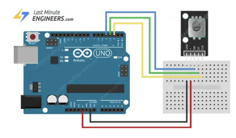
Rotary Encoder Wiring:
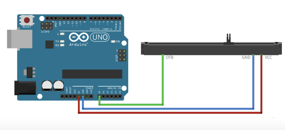
Slide Potentiometer Wiring:
