Aqua Arcade- A Pinball Odyssey
Context and Significance
Our midterm project drew inspiration from my previous group project “The Suit”. Just as I had previously combined ideas from pre-existing Black Panther’s vibranium/hydrogel suit and Iron Man’s design, I applied a similar creative process during our brainstorming session for this midterm project. Recognizing our shared love for simple games and nostalgia for childhood arcades, we decided to embark on the journey of recreating a pinball machine, adding our unique twist centered around ocean conservation.
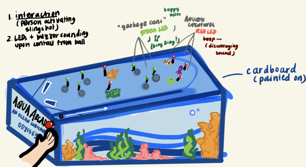
Initial Sketch (drawn by me)
We understood that the essence of interaction would be blatant in this project. Human actions would propel the ball through the machine, strategically hitting the flippers to navigate through various obstacles, fostering a tangible connection between the user and the object.
Through our preliminary research, we delved into the intricacies of a ‘Homemade Arduino Pinball Machine,‘ and closely examined the complex code and mechanics involved. Additionally, we looked at other arcade pinball machines for design inspiration, and brainstormed what we could do with the materials at hand. The Homemade sample we looked at was a marvel of complexity, boasting flippers, pop bumpers, an intricate playfield, and a powerful slingshot. The backside was a maze of interconnected wires, all linked to an Arduino Mega, which admittedly felt daunting to our group.
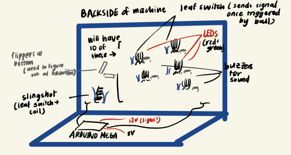
Initial sketch of Arduino (drawn by me)
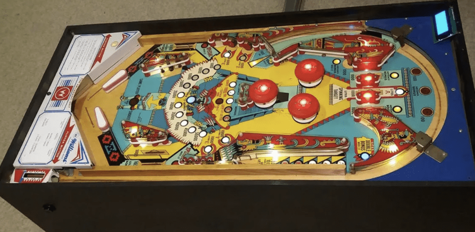
Arduino Project Hub by Frogger1108
In regards to my initial definition of interactivity, watching the countless videos of people playing the game evoked a vivid memory – the vibrant lights, joyful tunes accompanying moments of victory were the passive, deeper definition of interaction. The user overcoming the game’s obstacles to reach those bright, flashing lights and booming melodies embodied interactivity.
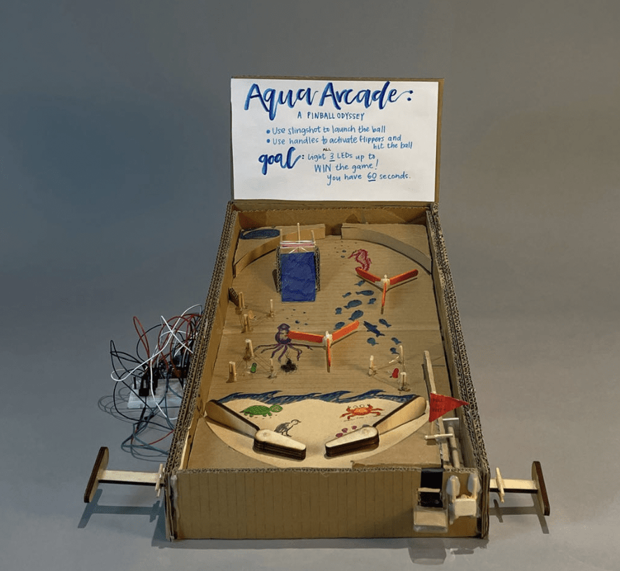
Thus, to enhance that feeling of interaction between user and project, we decided to recreate a pinball machine like none other. In contrast to typical arcade pinball machines with automatic pop bumpers and flashing decorative lights, our design sought to emphasize the user’s direct influence. The primary interaction revolved around the user activating the slingshot and skillfully using the flippers to illuminate all 3 of the LEDs. Hitting a triangle of wires would cause the corresponding LED to light up, but an accidental hit on the way down would extinguish it. The ultimate goal was to light up all three triangles, triggering a joyous melody that resembled a specific Mario tune.
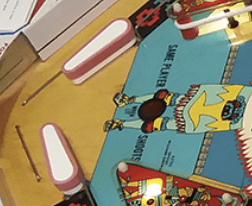
Our contribution to the recreation of the pinball machine was to introduce a singular objective to win the game, and to involve environmental significance. Initially, the theme was centered on “ocean conservation,” where the ball symbolized trash, and the user had to target “trash cans” to win (this meant you had successfully put trash away) and activate the music and lights. However, the thematic coherence was somewhat fragmented, as the machine’s overall decor featured cheerful aquatic creatures, rather than a more fitting “trashy” aesthetic.
Nonetheless, our pinball machine retained the timeless appeal of classic arcade games. It catered to players of all ages – kids, teenagers, and adults who fondly reminisced about the good old arcade days. Currently in Shanghai, and with arcades that focus more on “electronic gaming” and claw machines, I’ve noticed fewer pinball machines within the community. Our group’s project, in this context, provided a wholesome opportunity to rekindle those nostalgic memories.
Conception and Design
In every game, the users’ response is of utmost importance – how easily they can operate the switches, the learning curve involved in playing the game, the level of interactivity, and more. Our group harbored significant concerns about the actual mechanics and, as a result, devoted a substantial portion of our time to ensure that the mechanisms were as simple and seamless as possible.
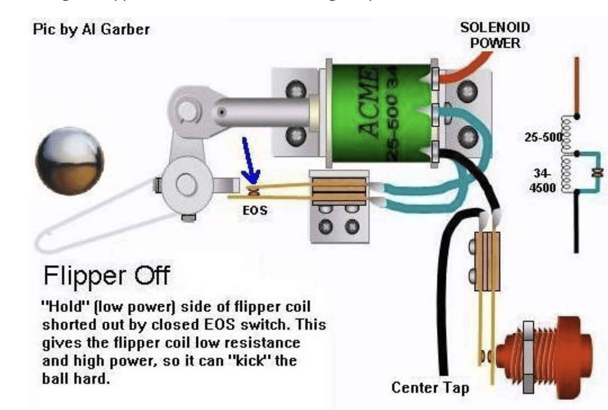
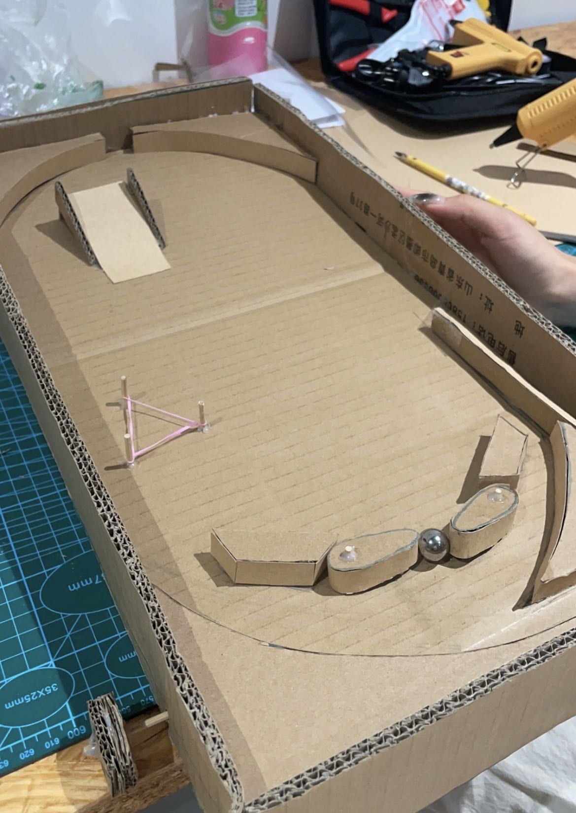
We faced two primary challenges: first, addressing the operation of the flippers, and second, dealing with the “bumpers” situated in the middle of the pinball machine. The former involved tackling the switches connected to the flippers. In the sample Arduino Project Hub, the flippers were intricately wired to a solenoid power system and coils, seemingly constructed from robust plastic materials. Given our time constraints, we decided to replicate the “coil-propelling” effect using elastic rubber bands. It was essential that the flippers possessed sufficient strength to propel the metal ball effectively, which led us to stack two to three pieces of cardboard together, creating a more durable material. For the mechanism behind the playfield, we utilized individual pieces of cardboard and skewer sticks. These components, when combined with the rubber bands, produced a pushing and flinging effect, allowing us to provide the desired action in a practical and efficient manner.
Arduino Project Hub by Frogger1108
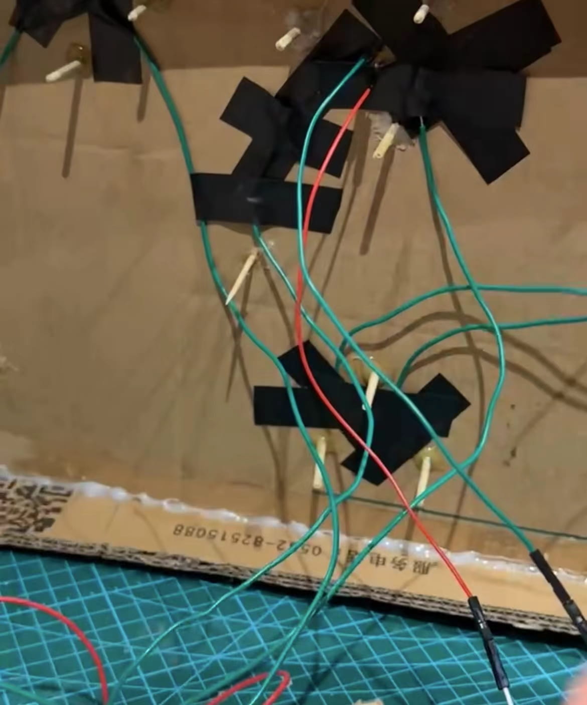
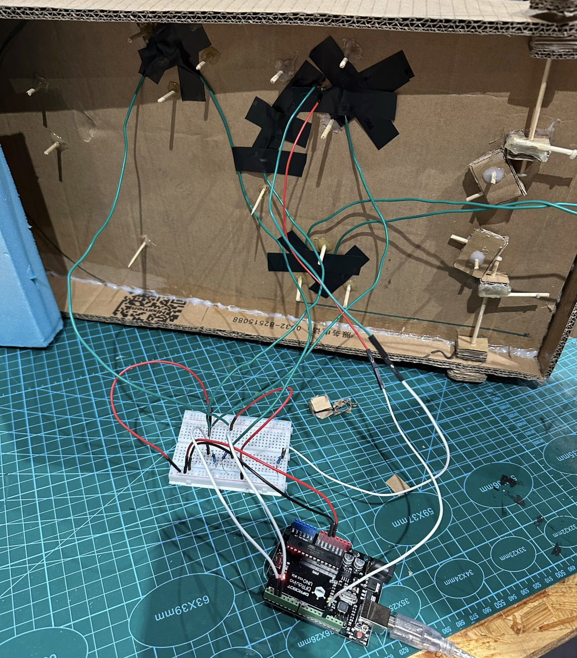
As for the bumpers, we initially faced a challenge due to a lack of available “pop bumpers.” Our initial plan involved using rubber bands strung along a set of triangular toothpicks. However, this setup presented a significant issue – there was no feasible way for the metal ball to establish a connection to light up the LED. The ball would come in contact with the rubber band and completely miss whatever wire we would insert there. (Thanks to Prof Andy’s idea…) We devised a solution using copper wire and the metal ball to mimic a makeshift switch. We strategically wound copper wire in front of the elastic so that the metal ball could make contact with the wire, thereby conducting electricity and activating the LED. After some trial and error, we concluded that the elastic was essentially unnecessary, and we stuck with just tightly winding the copper wire, serving both as a bumper and a conductor.
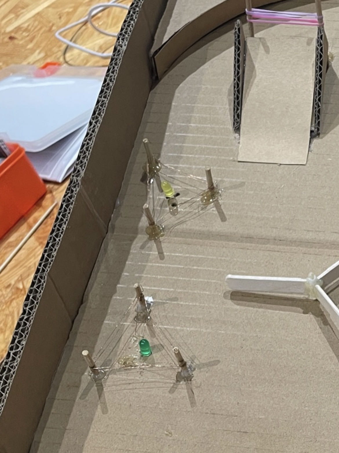
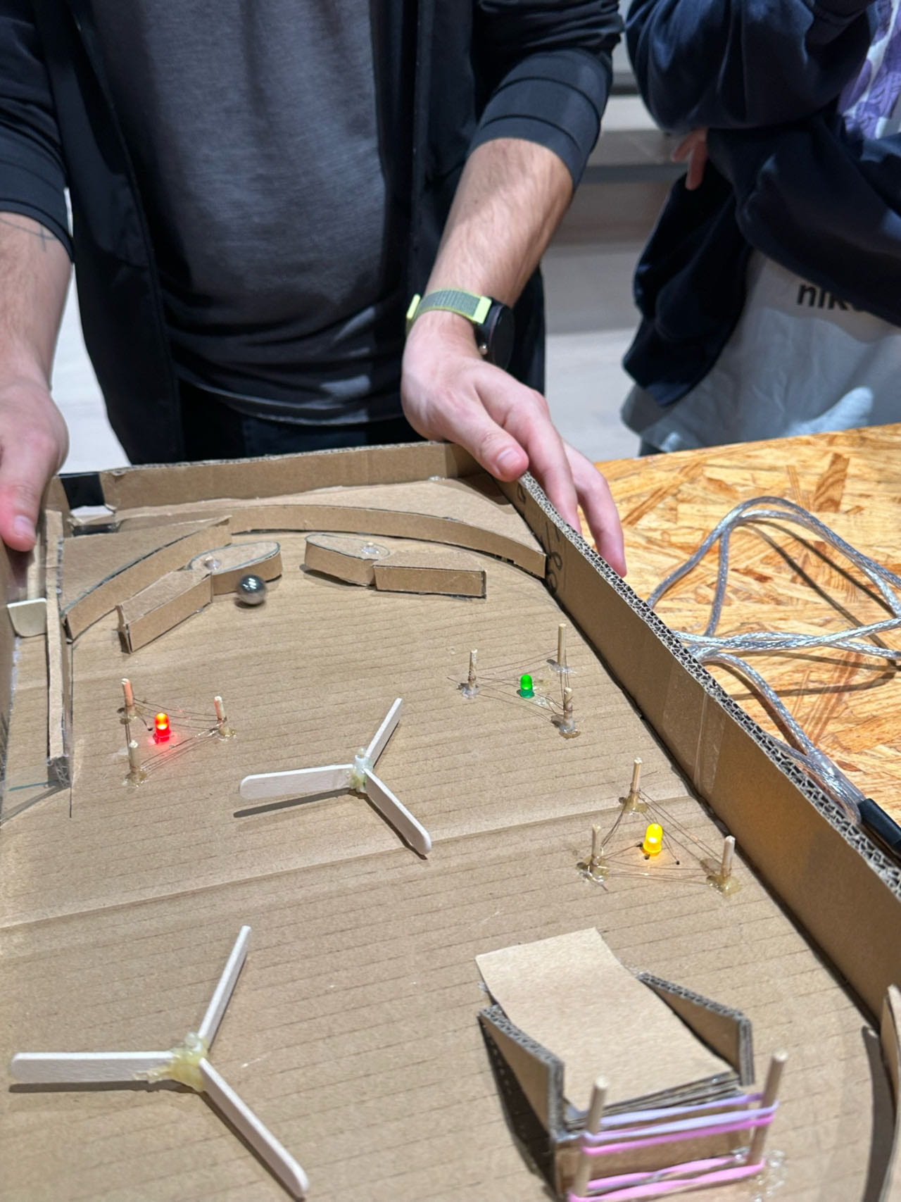
(LEFT) Copper Wire Triangles (RIGHT) LEDs lit up after metal ball touches wire
When it came to selecting our materials, we referred to our reference picture (sketch) and brainstormed various everyday household and dining utensils that we had readily available. This approach proved quite effective as it simplified the procurement process: we used chopsticks for the slingshot, hair rubber bands, skewer sticks from delivery, and the class-provided cardboard. During the prototyping phase, these materials were highly suitable for trial and error. We frequently adjusted measurements, had to remove components attached with hot glue, and having backup cardboard and skewer sticks at hand proved invaluable for replacements. By opting for these readily accessible materials, we ensured a smoother and more cost-effective development process, avoiding potential complications that might have arisen if we had invested in more specialized bumpers or coils.
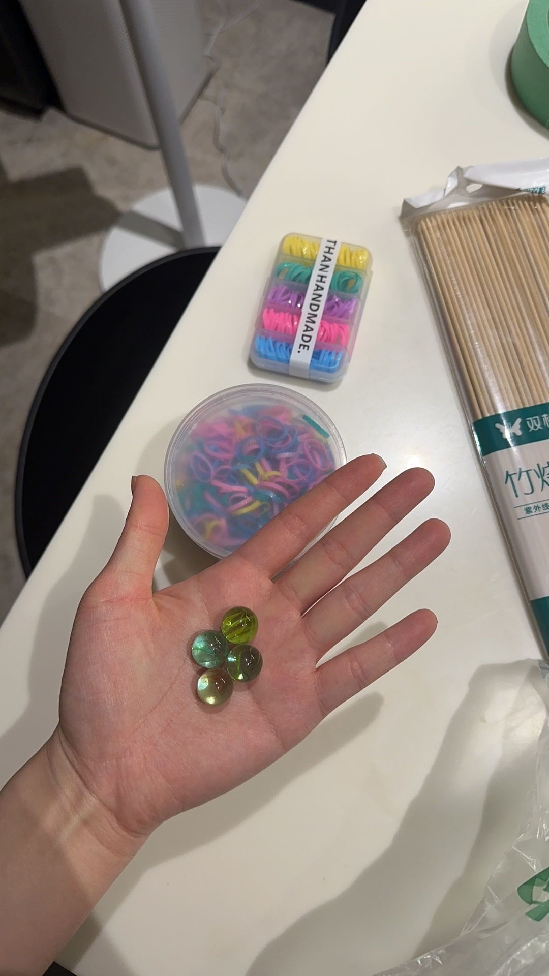
Initial Materials List: Marbles, Rubber Bands, Skewer Sticks
As we neared the finalization of our prototype, an exciting idea emerged – the addition of a glass surface to truly evoke that authentic arcade ambiance. While we had 3mm acrylic in the studio, we hesitated to cover the entire playfield with it due to the prototype’s construction from cardboard, as well as the presence of LEDs and rubber bands that could potentially require adjustments. We rejected this approach, as it would limit the flexibility to make changes as needed and the overall workability of our project.
Fabrication and Design
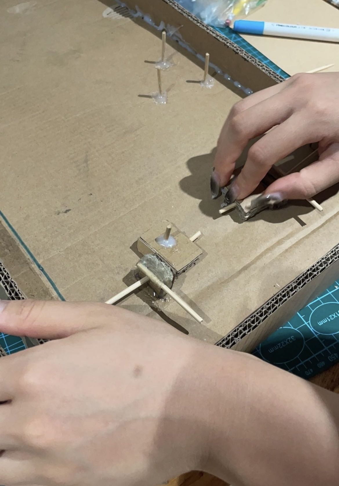
Delving into the most crucial steps of our production process, I must emphasize the significance of refining the flippers. While our prototype generally functioned well, it occasionally suffered from flippers slipping out of their sockets or getting stuck in the resistance of the elastic band. We dedicated around 3 to 4 hours brainstorming various methods to construct more reliable flipper switches and rectify the inconsistencies associated with the elastic. We explored multiple smaller prototype versions, initially experimenting with the cardboard stacking approach and later transitioning to the idea of laser-cutting wooden flippers. Our last-minute adoption of laser-cut wooden flippers was a significant triumph in our production process.This modification proved to be a game-changer, as it resulted in durable, precisely symmetrical flippers that were perfectly weighted to propel the metal ball. The positioning of toothpicks was also crucial – if placed too close, the flippers could become stuck, but if too far apart, they’d lose their resistance, causing the flippers to lose their effectiveness.
Flippers front and back (Prototype)
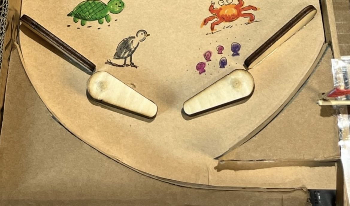
New Flipper (Final)
On the coding front, however, we encountered a less fluid process. The soldering of copper wires presented a persistent challenge, with wires breaking off unexpectedly. These wires were concealed beneath electrical tape, making it difficult to see whether they were connected or not. When the code malfunctioned, it confounded us further, leaving us uncertain about whether the issue lay with wire disconnections or coding problems. Cutting through layers of tape and meticulously unraveling the three sets of wires revealed that two had become unsoldered. We had to painstakingly re-solder four wires just hours before our project demonstration.
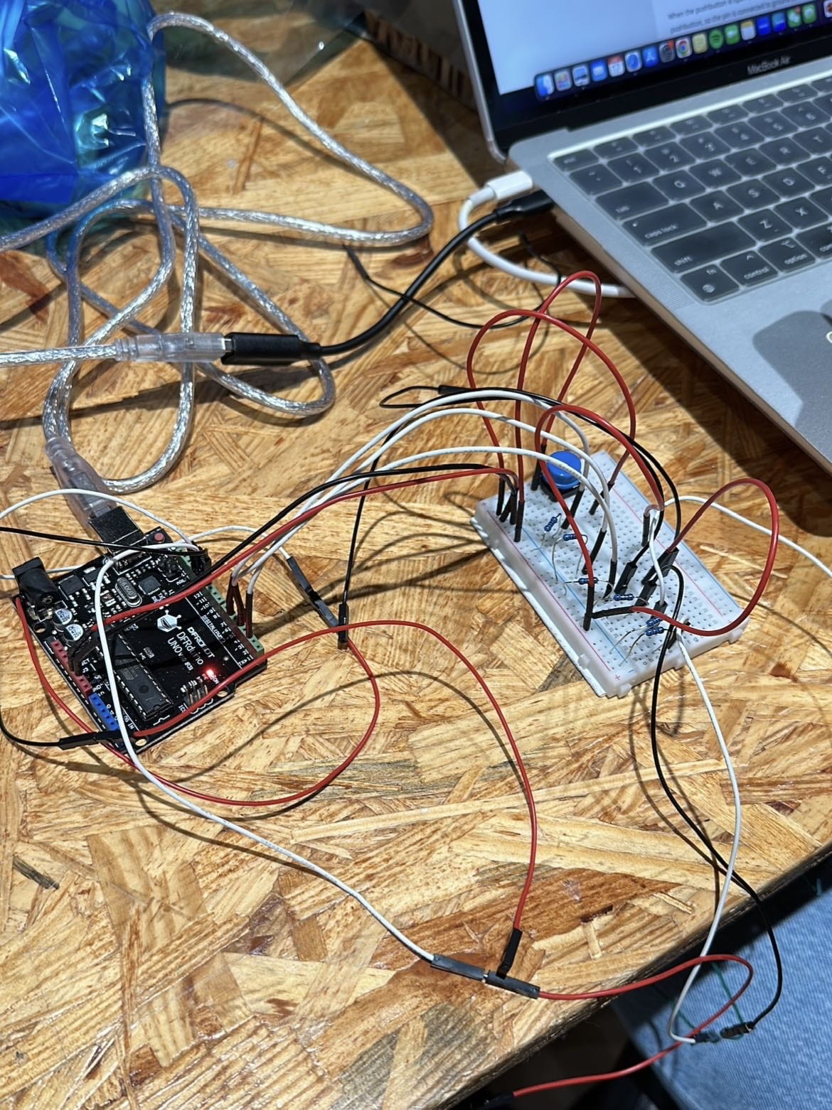
(LEFT) Soldered wires + LED connected to Arduino (RIGHT) Backside, soldered wires under electrical tape
In terms of roles within our group, I assumed a leadership role, establishing a preliminary timeline for purchasing materials and setting deadlines for specific tasks. Given my involvement in sketching the project proposal, I possessed a more comprehensive understanding of which components to construct first. This insight enabled me to delegate roles, assigning tasks like cutting pieces, gluing, and assembly to my group members. Our group dynamics were remarkably harmonious and well-suited to the project. One member demonstrated elevated proficiency with the wood saw and box cutter, while another displayed dexterity in handling hot glue and assembling various components. As the project progressed, I took on the responsibilities of wiring and coding, while my teammates focused on constructing the flipper mechanisms and copper wiring on the toothpicks. I actively participated in soldering the copper wires, connecting them to 10K resistors, different holes on the Arduino, and ensuring the proper functioning of the LEDs. With the guidance of LAs and professors, I eventually created a custom melody for the buzzer (for both victory and defeat), coded the wiring for LED illumination, and implemented the 60-second timer. As construction neared its end, I designed the instruction sign and personally added (my artistic flair) in the illustrations of aquatic sea creatures to the pinball machine.
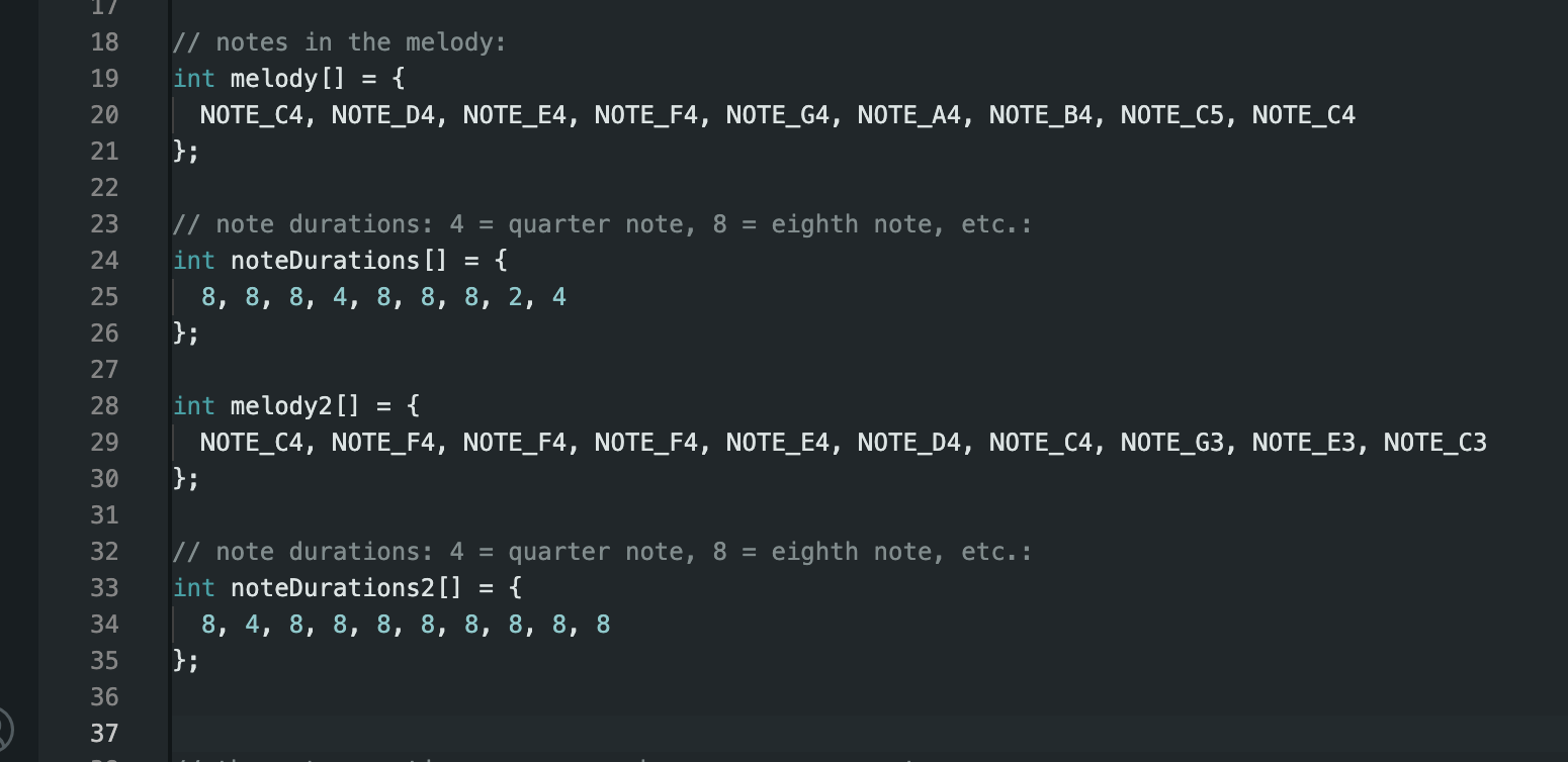
Code for win (melody) and lose (melody2)
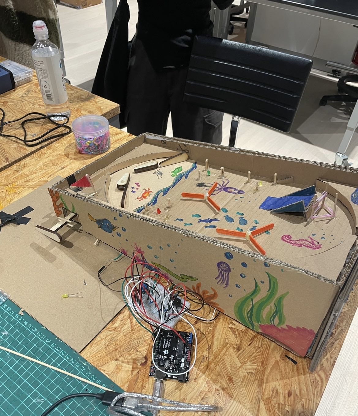
During our User Testing Session, our chosen user possessed significant prior experience with pinball machines, drawing from his childhood nostalgia. He offered valuable feedback, particularly regarding the propensity for flippers to become stuck due to inconsistencies in the rubber band resistance and the occasional difficulty in hitting wires surrounding the LEDs. Other visitors to our project, however, were unfamiliar with the game, often expressing confusion, and suggested the inclusion of an instruction sign to clarify the gameplay. LAs provided valuable input, challenging us to make the pinball machine more advanced and raised questions regarding scoring systems, music, and incentives for victory. They noted the absence of a scoring system and underlined the importance of auditory feedback. The space between the flippers was also criticized, as it sometimes hindered the ball’s path to the cubby for resetting. Additionally, since our prototype consisted solely of plain cardboard, decor became a prominent focus.
The feedback we received during user testing exerted a profound influence, with approximately 90% of our production decisions stemming from this process. We placed special emphasis on the flipper mechanisms, discarding the existing design in favor of a new, more reliable layout. We introduced popsicle sticks, repositioned the thick cardboard, and fine-tuned the structure to create smoother flipper action. The addition of a clearly written instruction sign outlining the objective and how to play the game addressed the confusion raised during user testing. The transformation of the plain cardboard exterior into a lively display of aquatic creatures and seaweed brought life to the pinball machine, making it visually appealing. On the coding front, I integrated two distinctive buzzer melodies, inspired by Mario theme songs, for both winning and losing scenarios. We also made adjustments to the placement of copper wires around the toothpicks, ensuring a tighter and more reliable circuit.
These adaptations proved highly effective. During a follow-up test with our designated user, we received overwhelmingly positive feedback regarding the improvements we had implemented. The flipper mechanisms functioned seamlessly, the ball interacted more smoothly with the wires, the LED lights lit up promptly, and the ball could easily pass through the flippers. The slingshot was more secure, and the overall visual presentation significantly enhanced the pinball machine’s appeal.
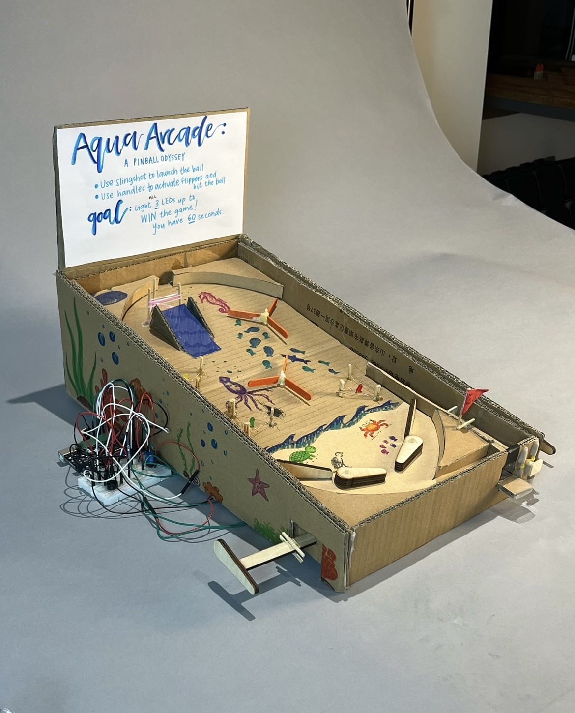
In alignment with our project’s goals, the pinball machine achieved a perfect balance of interactivity, nostalgic arcade charm, and appeal. The mechanics were straightforward enough to use, closely resembling a genuine arcade pinball game. The instruction sign clarified the objective, and while the game posed a challenge, two users successfully activated all three LEDs, achieving victory. Our production process demonstrated the capacity to adapt, evolve, and ultimately realize the desired project vision.
Conclusion
Our group embarked on a “Pinball Odyssey” with the primary goal of rekindling the timeless appeal of classic arcade games. We aimed to infuse an element of ocean conservation into the game, offering users not just entertainment but also an opportunity to relax. We set out to elevate the “interactivity” of the pinball machine, with a clear objective for players to win the game, accompanied by rewarding visual and auditory cues, such as vibrant LEDs and a cheerful melody upon victory.
Reflecting on this project, I believe it aligns with my definition of interaction, which involves a user triggering a response from a product. The experience of physically engaging with the game, from manipulating the flippers to releasing the slingshot, is a clear manifestation of interaction. Equally important is the visual and auditory feedback: the dazzling display of red, green, and yellow LEDs and the accompanying music upon success, juxtaposed with the illumination of the red LED and a somber melody when a player falls short under the 60-second time limit.
However, our expectations for the audience’s response yielded mixed results. Some testers were unfamiliar with the game, as it wasn’t a part of their culture or arcade experience. Consequently, the instructions might have seemed foreign, and they grappled with mastering the skill level required (managing the slingshot and flipper actions). On the other hand, we received positive feedback from other members of the audience, notably classmates who reminisced about their joyful experiences playing pinball during their childhood. They witnessed our project’s evolution during the construction process and were delighted to see the final product’s success.
Given more time, there are several aspects I would improve in our pinball machine. I would refine the “ocean conservation” theme by removing some of the fish and aquatic creatures, replacing them with littered plastic, water bottles, and other elements to achieve a more authentic “trashy theme.” I would also invest additional hours in comprehending the code to ensure that the 60-second timer activated when the user pressed the button, and the melody would play when they failed under the 60-second mark. Furthermore, I would choose more durable materials for the playfield’s base, possibly using the finer cardboard provided in class, while also increasing the overall size to accommodate more LEDs, wires, obstacles, and complexity. We had worked directly off of the prototype with weaker cardboard, so it had begun to wear out. The handle where the user’s hands rest could be enlarged, imitating the shape of a hand for added comfort. Finally, I would place greater emphasis on overexplaining the instructions to ensure clarity and understanding for all users.
Our journey was not without setbacks and failures, notably involving a grand total of 6 soldering issues, code malfunctions, and flipper jamming. However, I’ve learned the value of patience and the willingness to redo things meticulously to ensure their integrity. I’ve also discovered the importance of seeking assistance and guidance, even when it might initially feel embarrassing. Regardless, we tackled every obstacle head-on, with numerous trial and error attempts, and ultimately, these challenges led to successful solutions.
In terms of accomplishments, I gained a profound understanding that coding is not as difficult as I had once thought. Over the course of the project, I became proficient in interpreting code, understanding the significance of statements, and configuring wire and resistor placements. Our mechanisms functioned smoothly, with fewer issues compared to the prototype, making for a satisfyingly challenging game. When a user managed to activate all three LEDs and the euphoric melody filled the air, it was a moment of immense relief and accomplishment. We realized that, with our combined knowledge from class and our original creativity, we possess the capability to recreate and invent a wide variety of projects. Our journey through this pinball machine creation was truly a testament to our teamwork and our ability to bring our ideas to life with pride and determination.
Appendix:
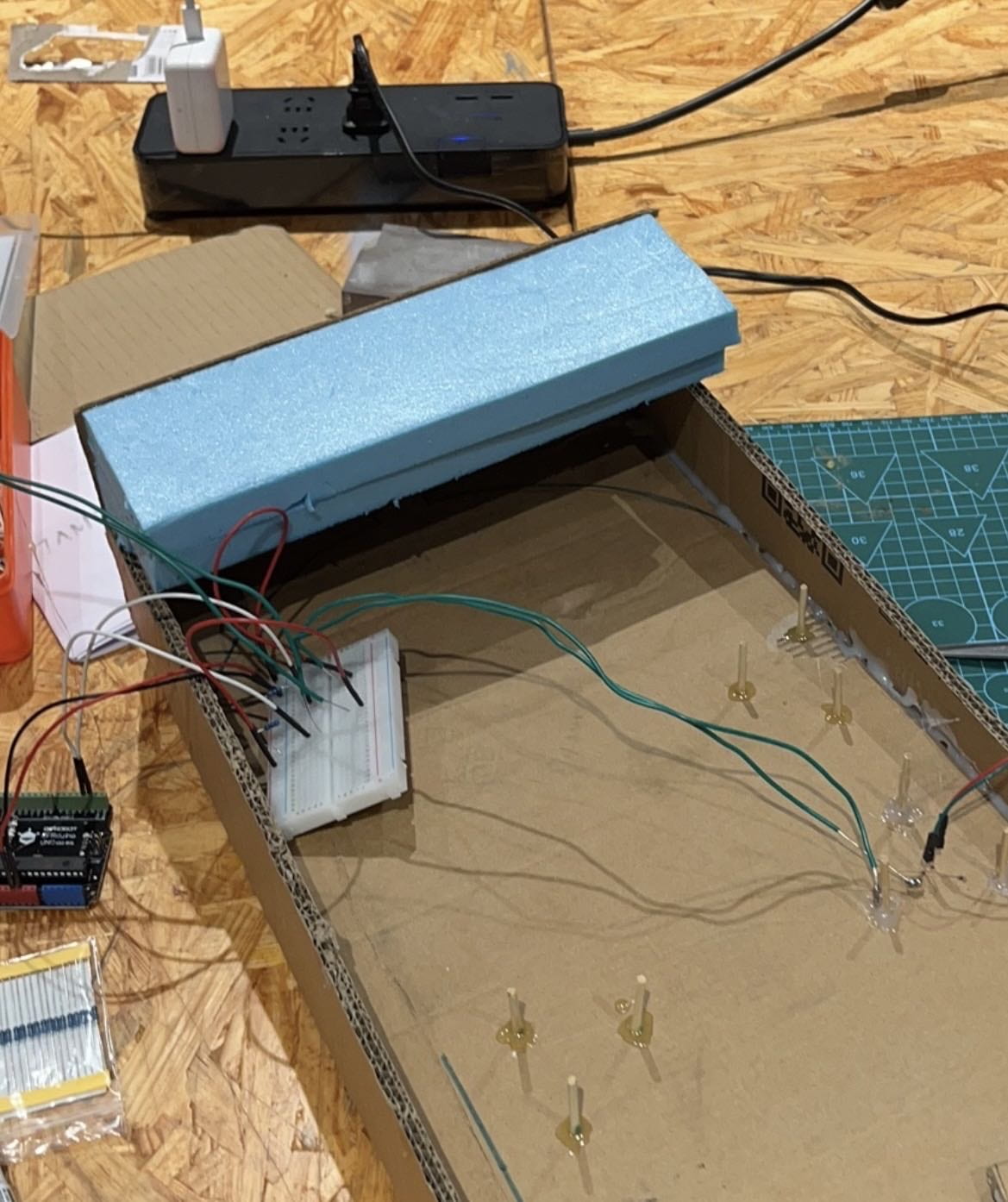
Wiring:
Final Product:
Code:
int pushButton1 = 2;  // wire 1
int pushButton2 = 6;  // wire 2
int pushButton3 = 4;  // wire 3
int pushButton4 = 8;  //start button
int led1 = 13;
int led2 = 12;
int led3 = 11;
int led1hitnum = 0;
int led2hitnum = 0;
int led3hitnum = 0;
//int buttonState = 0;

long startTime = -1;  // starts out as stopped


#include "pitches.h"

// notes in the melody:
int melody[] = {
  NOTE_C4, NOTE_D4, NOTE_E4, NOTE_F4, NOTE_G4, NOTE_A4, NOTE_B4, NOTE_C5, NOTE_C4
};

// note durations: 4 = quarter note, 8 = eighth note, etc.:
int noteDurations[] = {
  8, 8, 8, 4, 8, 8, 8, 2, 4
};

int melody2[] = {
  NOTE_C4, NOTE_F4, NOTE_F4, NOTE_F4, NOTE_E4, NOTE_D4, NOTE_C4, NOTE_G3, NOTE_E3, NOTE_C3
};

// note durations: 4 = quarter note, 8 = eighth note, etc.:
int noteDurations2[] = {
  8, 4, 8, 8, 8, 8, 8, 8, 8, 8
};


// the setup routine runs once when you press reset:
void setup() {
  // initialize serial communication at 9600 bits per second:
  Serial.begin(9600);
  // make the pushbutton's pin an input:
  pinMode(pushButton1, INPUT);
  pinMode(pushButton2, INPUT);
  pinMode(pushButton3, INPUT);
  pinMode(pushButton4, INPUT);
  pinMode(led1, OUTPUT);
  pinMode(led2, OUTPUT);
  pinMode(led3, OUTPUT);
}

// the loop routine runs over and over again forever:
void loop() {
  int buttonState4 = digitalRead(pushButton4);
  // print out the state of the button:
  //Serial.println(buttonState);
  delay(1);  // delay in between reads for stability // moved up from loop, green and yellow don't work


  // // read the input pin:
  int buttonState = digitalRead(pushButton1);
  //print out the state of the button:
  //Serial.println(buttonState);
  delay(10);  // delay in between reads for stability
  if (buttonState == 1) {
    //Serial.println(led1hitnum);
    led1hitnum = led1hitnum + 1;
    if (led1hitnum % 2 == 1) {
      digitalWrite(led1, HIGH);
    } else {
      digitalWrite(led1, LOW);
    }

    delay(100);
  }
  int buttonState2 = digitalRead(pushButton2);
  //Serial.println(buttonState2);


  delay(10);  // delay in between reads for stability
  if (buttonState2 == 1) {
    //Serial.println(led2hitnum);
    led2hitnum = led2hitnum + 1;
    if (led2hitnum % 2 == 1) {
      digitalWrite(led2, HIGH);
    } else {
      digitalWrite(led2, LOW);
    }

    delay(100);
  }

  int buttonState3 = digitalRead(pushButton3);

  // print out the state of the button:
  //Serial.println(buttonState3);
  delay(10);  // delay in between reads for stability
  if (buttonState3 == 1) {
    //Serial.println(led3hitnum);
    led3hitnum = led3hitnum + 1;
    if (led3hitnum % 2 == 1) {
      digitalWrite(led3, HIGH);
    } else {
      digitalWrite(led3, LOW);
    }

    delay(100);
  }

  if (buttonState4 == HIGH) {
    startTime = millis();

    tone(7, 262);  //
    delay(500);
    noTone(7);
  }

  if (led1hitnum % 2 == 1 && led2hitnum % 2 == 1 && led3hitnum % 2 == 1) {
    if (millis() - startTime < 60000) { win(); } } if (startTime != -1 && millis() - startTime > 60000) {
    noTone(7);       // turn it off
    startTime = -1;  // mark as stopped again
  }

  Serial.println(millis() - startTime);
  //Serial.println(millis() - startTime);


    if (millis() - startTime > 600000) {
      lose();
    }

}


void win() {
  //for(int thisNote = 0; thisNote < 9; thisNote++) {
  for (int thisNote = 0; thisNote < 9; thisNote++) {
    // to calculate the note duration, take one second divided by the note type.
    //e.g. quarter note = 1000 / 4, eighth note = 1000/8, etc.
    int noteDuration = 1000 / noteDurations[thisNote];
    tone(7, melody[thisNote], noteDuration);

    // to distinguish the notes, set a minimum time between them.
    // the note's duration + 30% seems to work well:
    int pauseBetweenNotes = noteDuration * 1.30;
    delay(pauseBetweenNotes);
    // stop the tone playing:
    noTone(7);
    digitalWrite(led1, LOW);
  }
  delay(10000);
}

void lose() {
  for (int thisNote = 0; thisNote < 12; thisNote++) {

    // to calculate the note duration, take one second divided by the note type.
    //e.g. quarter note = 1000 / 4, eighth note = 1000/8, etc.
    int noteDuration = 1000 / noteDurations2[thisNote];
    tone(7, melody2[thisNote], noteDuration);

    // to distinguish the notes, set a minimum time between them.
    // the note's duration + 30% seems to work well:
    int pauseBetweenNotes = noteDuration * 1.30;
    delay(pauseBetweenNotes);
    // stop the tone playing:
    noTone(7);
    digitalWrite(led1, HIGH);
  }
  delay(10000);
}
/*************************************************
   Public Constants
 *************************************************/
#define NOTE_B0 31
#define NOTE_C1 33
#define NOTE_CS1 35
#define NOTE_D1 37
#define NOTE_DS1 39
#define NOTE_E1 41
#define NOTE_F1 44
#define NOTE_FS1 46
#define NOTE_G1 49
#define NOTE_GS1 52
#define NOTE_A1 55
#define NOTE_AS1 58
#define NOTE_B1 62
#define NOTE_C2 65
#define NOTE_CS2 69
#define NOTE_D2 73
#define NOTE_DS2 78
#define NOTE_E2 82
#define NOTE_F2 87
#define NOTE_FS2 93
#define NOTE_G2 98
#define NOTE_GS2 104
#define NOTE_A2 110
#define NOTE_AS2 117
#define NOTE_B2 123
#define NOTE_C3 131
#define NOTE_CS3 139
#define NOTE_D3 147
#define NOTE_DS3 156
#define NOTE_E3 165
#define NOTE_F3 175
#define NOTE_FS3 185
#define NOTE_G3 196
#define NOTE_GS3 208
#define NOTE_A3 220
#define NOTE_AS3 233
#define NOTE_B3 247
#define NOTE_C4 262
#define NOTE_CS4 277
#define NOTE_D4 294
#define NOTE_DS4 311
#define NOTE_E4 330
#define NOTE_F4 349
#define NOTE_FS4 370
#define NOTE_G4 392
#define NOTE_GS4 415
#define NOTE_A4 440
#define NOTE_AS4 466
#define NOTE_B4 494
#define NOTE_C5 523
#define NOTE_CS5 554
#define NOTE_D5 587
#define NOTE_DS5 622
#define NOTE_E5 659
#define NOTE_F5 698
#define NOTE_FS5 740
#define NOTE_G5 784
#define NOTE_GS5 831
#define NOTE_A5 880
#define NOTE_AS5 932
#define NOTE_B5 988
#define NOTE_C6 1047
#define NOTE_CS6 1109
#define NOTE_D6 1175
#define NOTE_DS6 1245
#define NOTE_E6 1319
#define NOTE_F6 1397
#define NOTE_FS6 1480
#define NOTE_G6 1568
#define NOTE_GS6 1661
#define NOTE_A6 1760
#define NOTE_AS6 1865
#define NOTE_B6 1976
#define NOTE_C7 2093
#define NOTE_CS7 2217
#define NOTE_D7 2349
#define NOTE_DS7 2489
#define NOTE_E7 2637
#define NOTE_F7 2794
#define NOTE_FS7 2960
#define NOTE_G7 3136
#define NOTE_GS7 3322
#define NOTE_A7 3520
#define NOTE_AS7 3729
#define NOTE_B7 3951
#define NOTE_C8 4186
#define NOTE_CS8 4435
#define NOTE_D8 4699
#define NOTE_DS8 4978

/**
* Buzzer melody
* This was adapted from a the tutorial found here:
* https://www.arduino.cc/en/Tutorial/BuiltInExamples/ToneMelody

*/