Project Title: Stayin Alive | Name: Serena Cajigal | Instructor: Andy Garcia
Preface
Originally, I started the final project solo. My initial concept was to make an interactive game between two users, utilizing heartbeat sensors. The initial design of the project was going to resemble a heartbeat monitor as a nod to my earliest idea, which was a heartbeat visualizer that could be used in a medical setting. I turned that idea into a game instead because I wanted my project to be more interactive and engaging, rather than just a single input-output art installation.
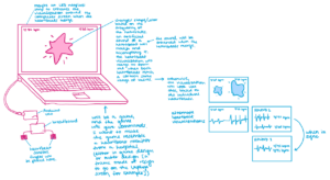
However, I realized that I did not have enough time or means to create this by myself. Therefore, I joined forces with my friend, Cassandra, and merged our project ideas. Her initial idea was to create a launchpad and music visualizer combination, which was similar to my project (the visualizing component). That being the case, we decided to turn our project into a collaborative game, both incorporating my heartbeat sensors and her music, while still keeping the visualization aspect.
Conception and Design
The concept of our combined project was a game based on synchronization of heartbeats; two players would have to work together to match each other’s heart rhythm. If the players managed to match each other’s heart rate at a specific BPM (beats per minute), the song “Stayin’ Alive” would then play and the monitor (that contained both BPMs) would display a visualization that correlated with the song. We chose “Stayin’ Alive” as the song to play because the BPM of “Stayin’ Alive” is the same BPM that one is supposed to use when performing CPR on someone. Our original song was “Sober” by BIGBANG, but that music selection did not make sense for the theme or meaning of our project.
During the User Testing Section, our user testers recommended that we improve the design of our game to make it match the theme or point of the game better. We were also told to make it “cuter.” Therefore, we made a pink, laser-printed, heart-shaped box to keep our wires and circuits. I believe that this change in the design improved the project by a lot. Since our project during the User Testing was still in its early stages, there was no context, so that is why we decided to include directions/visual aids in our design. We also attempted to incorporate these directions into our Processing code for the visuals in the form of text. These directions in Processing would have been very useful, but we could not incorporate text into our code without making everything in the code lag. Therefore, we opted for directions that were pasted directly on the heart box that stated, “Follow the beat.” Although it still confused users who tested it, this did provide more context.
Fabrication and Production
When constructing our project, we initially put all of our wires and circuits into a tiny, laser-printed box. For the basis of our wiring, we used the example from Last Minute Engineers for the pulse sensors. As mentioned above, the tiny and almost bare design of the box did not complement the purpose or theme of our project, so we created a large, pink heart.
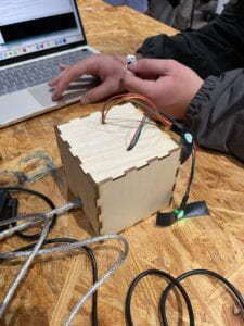
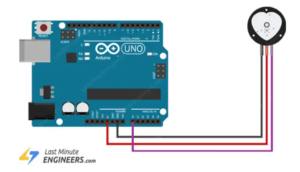
However, throughout the entire process, my partner and I had been having trouble with the Arduino code and getting the heartbeat sensors to work; when we tried to test the sensors, they would either give scarily inaccurate results, or both of the sensors would record the same data despite being separate. Therefore, to separate them, we utilized two Arduino Unos and connected them to separate baud rates on Arduino. This succeeded in separating the heartbeat sensors, but the results produced by the sensors were inconsistent and buggy each time.
After almost a week of trying to debug to no avail, we had no choice but to change the heartbeat sensors into pressure sensors. The pressure sensors were a good alternative because they essentially did the same thing as the heartbeat sensors function-wise, except that the “heartbeats” were to be done manually by the users instead. This turned our project into a rhythm game, which made it easier for the users to win the game.
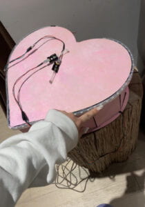
After we achieved this, we decided to laser cut a mini, semi-transparent acrylic heart-shaped box to sit on top of the wooden heart box (similar to a cake) to make the design cuter. To hide the wire connection of the pressure sensors, we covered it with cotton to give the project a softer appearance. We then attached the sensors to acrylic hearts, as they were the leftovers from the laser-cutting of the mini-heart box; I loved it because it reminded me of miniature remote controls.
To enhance the visuals, we stuffed an LED Neopixel inside this miniature box. Before, the LED Neopixels were stuck to the outer rims of the heart box, but we decided to relocate it inside of the miniature heart box because it looked more visually pleasing, and the wires from the Neopixel were not visible, as we had cut a hole inside the area that the mini-heart occupied to connect the LEDs to the Arduino Uno. We also covered the base of the acrylic mini-heart with cotton to match the overall design (and it looked a bit like cake icing), and we added mini LEDs inside of the heart box to blink when the sensors were activated; this made the heart look like it was beating. In hindsight, I believe this was a great move on our part because the cute design compensated for the bugged code.
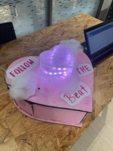
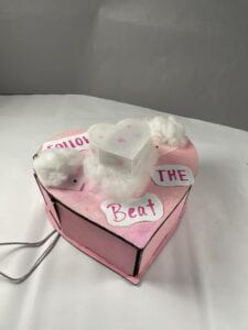
Finally, here is the final working product:
Here is a run-through of the gameplay with commentary:
Conclusion
This project encourages teamwork and collaboration, and it promotes an even deeper message of the tight-knit relationship between life and music. Music keeps us alive and keeps us imaginative, innovative, and upbeat. The goal of the project was to remind others of this fact, as shown through the use of “Stayin’ Alive” (the CPR song) as the song that users had to keep the rhythm of.
The audience responded positively towards this project for the most part; although it was quite difficult for first-time players to win the game when they finally did, the project was met with enthusiasm. However, due to the lack of directions in the final product, it was expected that the audience would be slightly confused. When the audience played the game, it was as if both players were performing CPR on the big heart box, which I believe added to the overall game experience.
I define interaction as a back-and-forth engagement between two or more people or things. It is a dynamic relationship that causes something to happen. Therefore, I believe that my project results did align with my definition of interaction. If I had more time, however, I would fix the code, add more directions, and improve the overall design of the Processing visualization and perhaps the outer design of the heart box as well. Though, I am pretty happy about the result of the project.
When making our project, my partner and I stayed up late in the interaction lab every day for a week leading up to the due date of the final project. This whole experience has taught me that I would never have been able to accomplish the things that my partner and I have accomplished, had I worked on this project alone—the ability to balance and collaborate is an important life skill, and my partner and I have definitely mastered this skill. All of our setbacks due to buggy code, laser cutting problems, and malfunctioned sensors tested our problem-solving and creativity while enhancing our teamwork. Because of all of this, I am proud of how far we have come and how hard we worked. In the end, if I could go back in time, I don’t think I would do things any differently. Shout out to Cassandra Du 🙂
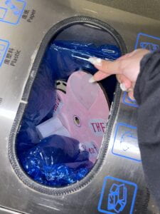
Disassembly
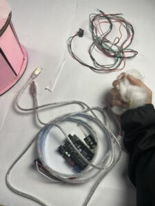
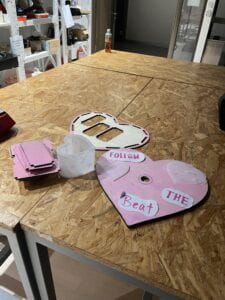
Appendix
Arduino code:
|
#define USE_ARDUINO_INTERRUPTS true // Set-up low-level interrupts for most acurate BPM math. #include <FastLED.h> //EXTRA CRGB leds[NUM_LEDS]; // Variables PulseSensorPlayground pulseSensor; // Creates an instance of the PulseSensorPlayground object called “pulseSensor” void setup() { Serial.begin(9600); // For Serial Monitor // Configure the PulseSensor object, by assigning our variables to it. // Double-check the “pulseSensor” object was created and “began” seeing a signal. FastLED.addLeds<NEOPIXEL, DATA_PIN>(leds, NUM_LEDS); void loop() { if (pulseSensor.sawStartOfBeat()) { // Constantly test to see if “a beat happened”. delay(20); // considered best practice in a simple sketch. while (Serial.available()) { //EXTRA |
Processing code:
//for the final processing sketch

import processing.serial.*;
import processing.sound.*;

Serial serialPort;
Serial serialPort2;

int NUM_OF_VALUES_FROM_ARDUINO = 1;  /* CHANGE THIS ACCORDING TO YOUR PROJECT */
int NUM_OF_VALUES_FROM_ARDUINO2 = 1;

/* This array stores values from Arduino */
int arduino_values[] = new int[NUM_OF_VALUES_FROM_ARDUINO];
int arduino_values2[] = new int[NUM_OF_VALUES_FROM_ARDUINO2];

int stage = 0;
SoundFile stayingalive;
SoundFile WeDidIt;
SoundFile sixbpm;
Amplitude analysis;

int NUM_LEDS = 60;
color[] leds = new color[NUM_LEDS];


void setup() {

  size(1600, 900);
  frameRate(30);

  //size(500, 500);
  background(0);

  //metronome
  sixbpm = new SoundFile(this, "60bpm.mp3");
  sixbpm.play();

  //printArray(Serial.list());
  // put the name of the serial port your Arduino is connected
  // to in the line below - this should be the same as you're
  // using in the "Port" menu in the Arduino IDE
  serialPort = new Serial(this, "COM3", 9600);
  serialPort2 = new Serial(this, "COM8", 19200);

  //text
  fill(#EAB4B4);
  textSize(150);
  strokeWeight(2);
  textAlign(CENTER);
  text("REMEMBER THE BEAT!", width/2, height/2);

  stayingalive = new SoundFile(this, "staying alive (chorus).mp3");
  WeDidIt = new SoundFile(this, "We Did It!.mp3");

  println("Loading mp3...");

  delay(5000);
  sixbpm.stop();

  analysis = new Amplitude(this);
  analysis.input(stayingalive);
}


void draw() {

  background(0);
  stroke(255);
  fill(255);

  // receive the values from Arduino
  getSerialData();
  getSerialData2();

  // use the values like this:
  int size1 = int(map(arduino_values[0], 0, 150, 0, width/2));
  int size2 = int(map(arduino_values2[0], 0, 150, 0, width/2));
  circle (100, height/2, size1);
  circle (400, height/2, size2);
  background (0);

  if (arduino_values[0]>=55 && arduino_values[0]<=65 && arduino_values2[0]>=55 && arduino_values2[0]<=65) {
    if (stayingalive.isPlaying()== false) {
      stayingalive.play();
    }
  }
  if (arduino_values[0]>=94 && arduino_values[0]<=102 && arduino_values2[0]>=94 && arduino_values2[0]<=102) {
    if (WeDidIt.isPlaying()== false) {
      stayingalive.stop();
      delay(20);
      WeDidIt.play();
      analysis.input(WeDidIt);
    }
  }

  float volume = analysis.analyze();
  float stayingalive = map(volume, 0, 1, 0, 60);
  float WeDidIt = map(volume, 0, 1, 0, 60);
  //println(volume);

  for (int i=0; i < NUM_LEDS; i++) {     // loop through each pixel in the strip
    if (i < volume * NUM_LEDS) {     // based on where we are in the song
      leds[i] = color(#AD1313);
    } else {
      leds[i] = color(#ED7878);
    }

    float diameter = map(volume, 0, 1, 0, width);
    // draw a circle based on the soundfile's amplitude (volume)
    fill(#ED7878);
    noStroke();
    circle(width/2, height/2, diameter);
    //float progress = sound.position() / sound.duration();
    //println(progress);     // find out where we are in the song (0.0-1.0)
  }

  sendColors();     // send the array of colors to Arduino
}


// the helper function below receives the values from Arduino
// in the "arduino_values" array from a connected Arduino
// running the "serial_AtoP_arduino" sketch
// (You won't need to change this code.)

void getSerialData() {
  while (serialPort.available() > 0) {
    String in = serialPort.readStringUntil( 10 );  // 10 = '\n'  Linefeed in ASCII
    if (in != null) {
      print("From A1: " + in);
      String[] serialInArray = split(trim(in), ",");
      if (serialInArray.length == NUM_OF_VALUES_FROM_ARDUINO) {
        for (int i=0; i<serialInArray.length; i++) {
          arduino_values[i] = int(serialInArray[i]);
        }
      }
    }
  }
}


void getSerialData2() {
  while (serialPort2.available() > 0) {
    String in = serialPort2.readStringUntil( 10 );  // 10 = '\n'  Linefeed in ASCII
    if (in != null) {
      print("From A2: " + in);
      String[] serialInArray = split(trim(in), ",");
      if (serialInArray.length == NUM_OF_VALUES_FROM_ARDUINO2) {
        for (int i=0; i<serialInArray.length; i++) {
          arduino_values2[i] = int(serialInArray[i]);
        }
      }
    }
  }
}


void sendColors() {
  byte[] out = new byte[NUM_LEDS*3];
  for (int i=0; i < NUM_LEDS; i++) {
    out[i*3]   = (byte)(floor(red(leds[i])) >> 1);
    if (i == 0) {
      out[0] |= 1 << 7;
    }
    out[i*3+1] = (byte)(floor(green(leds[i])) >> 1);
    out[i*3+2] = (byte)(floor(blue(leds[i])) >> 1);
  }
  serialPort.write(out);
}
Wiring (pretend the Micro Servos are pressure sensors):
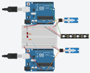
// For the basis of the Arduino to Processing code, we used the Arduino to Processing example given in class
// For the Neopixels, we also used the example code given in class