Evolving Virtual Creatures:Karl Sim’s Virtual Creatures

Evolving Virtual Creatures

Link to slides:https://docs.google.com/presentation/d/1u3ku1ZeubXsbXU8jDdwYmSOl5FgtYG1HD41C4jKLy_0/edit?usp=sharing

Creating process:

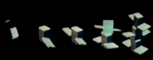
The project involves simulated Darwinian evolutions of some virtual block creatures generated by computers, which consist of digital brains and physical bodies. Digital genes are stored to describe their physical features. Creatures will be sorted by the computer, and the survivors will combine with each other to make offspring.
 

Features:

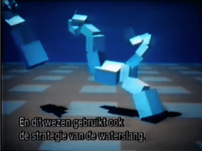
  1. Visual: The creatures are made up of blocks linked together. They follow the laws of physics to move.
  2. Technical: The creatures combine their genes to generate more adequate physical features to survive in this digital space. The user can set the condition of the environment and wait for the creatures to evolve by themselves.
  3. Material: These creatures “live” in a virtual computer world that mimics the real physical world.


Forms of interaction

These creatures don’t actually interact with observers. They have an inner interactive chain, and when they perform an ideal move, the feature that enables them to do this move will be kept and developed.

Intentions

The research intends to do research on the virtual ecosystem and how computers can realize the Darwinian evolving process. He successfully created this virtual environment and made some virtual creatures that can imitate real creatures well. It has verified the possibility for humans to create a “real” virtual world in the future with more advanced technology.

Views

The researcher thinks that this process enables people to generate complicated creatures with simple prompts. It’s a new discovery in artificial generative arts.
Background

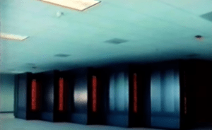
Karl Sims is a computer graphics artist and researcher who excels at using particle systems and artificial life generation in computer animation. After graduating from MIT, he worked at Thinking Machines, which used to be an AI company that released several powerful supercomputers. He was awarded many times for his groundbreaking research in digital arts.

Methods

Optimization techniques help automatically generate complex creatures. The researcher uses the Darwinian “survival of the fittest” approach to search for optima. They then use interactive evolution to procedurally generate results that can be explored by simply choosing the most desirable individuals, mixing their genes, and repeating this process.

Inspirations

This project might be the beginning of creating digital ecosystems and making self-evolving digital creatures. The researcher might have been inspired by the status quo at that time when people were able to develop methods to make digital objects to do movement but only with complicated algorithms, so this research aimed to explore the possibilities of generating moving methods by automatically evolving.
Historical Context

This research was conducted over 20 years ago when there was no advanced generative AI technology like ChatGPT or Stable Diffusion. Though the interface is very simple, it is still an advanced exploration of generative arts.


Discussion

Significance:  This research aims to achieve the reappearance of Darwin’s evolving theory using virtual creatures that could algorithmically self-evolving, which opened up a whole new area of artificial life that goes across biology, computer science, and visual art. Moreover, the study offered a new approach to automatically generate complex motion control algorithms under several environments.

Relation between the concepts we are learning in CCLab: Such a study involves various methods to generate complex object-to-object interaction on a 3D platform while attaching a self-developing algorithm to a visual art product. The research also adapts virtual simulation to basic physical elements such as force, movement, speed, etc.

Takeaways and inspiration: The idea of having an algorithm that develops itself could give visual arts a new layer of interactivity: let the outcome inspire the user, rather than only letting the user express their creativity. Having the idea of machine learning involved could expand the user’s experience time.


Individual Conclusion

Rebecca: This project includes automatically generating the physical appearance and movement of creatures. It makes me think of another more recent research video about making AI teach itself to walk. In this video, the mini AI creature learned how to walk on two feet independently. The generative arts can produce some outcomes that can’t be occurred to an ordinary person and then stimulate their creativity. These projects have proved the possibility of creating a completely automatically generated AI ecosystem in the future that we can experience through VR devices, or even live in. It inspired me that I can make a creature for my first big project that can automatically modify its appearance and behavior to adjust a randomly generated environment.


Sean: The project describes a system for creating virtual creatures using genetic algorithms and physical simulation. The creatures’ morphologies and neural systems are generated automatically, and different fitness evaluation functions are used to direct simulated evolutions towards specific behaviors such as swimming, walking, jumping, and following. The most inspiring part to me is the evolving theory of having several sets of competitions with a specific task in an arena to judge the advantages and disadvantages of changes in genetic layers. I would have a lot of interest in introducing these competitive rules into my coming big project.
CClab mini project2

Project title: Trisha’s Floating Dream

Link to the project:https://editor.p5js.org/N-A-E-S/sketches/N5_MncvSk

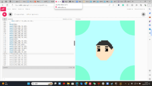
Description: This P5js work is based on the selfie from Trisha, who depicted her dream of everything around her floating and changing color. According to her description, I added some animation to her selfie and produced this work.

Visual Documentation:

Coding:

To achieve the animation of floating, I decided to introduce a variable to count the time. The reason why I didn’t choose frameCount is that this number increases too fast to control the movement, and decreasing the frameset would influence the tracking to the mouse position. Thus I introduced a variable t that increased 0.01 each frame. To limit the movement of all triangles, I decided to times a sin() function or cos() function after the Y axis of triangles.

 noStroke();
  fill(154, 205*cos(t), 155*sin(t));
  triangle(200, 100+15*sin(t), 200, 200+15*sin(t), 350, 100+15*sin(t));
  
  fill(255, 225*cos(t), 75*sin(t));
  triangle(40, 100+15*cos(t), 200, 25+15*cos(t), 100, 150+15*cos(t));
    
  fill(255*sin(t), 50, 175);
  triangle(400, 150-5*sin(t), 300, 50-5*sin(t), 380, 10-5*sin(t));
    
  fill(154, 212, 54);
  triangle(0, 70, 150, 0, 0, 0);
    
  fill(126*cos(t), 235*sin(t), 184*cos(t));
  triangle(0, 100+15*sin(t), 50, 200+15*sin(t), 100, 200+15*sin(t));
  
  fill(126, 270, 184);
  triangle(200, 50+15*cos(t), 260, 10+15*cos(t), 250, 70+15*cos(t));

 with the triangle functions, these triangles will slowly move around within 30 pixels,  acting as if they are floating.

Also, I used the same method to achieve the switching of color

Then I expected to achieve the function of keeping the eyes looking at the mouse, so I used a module function to control the distance, which eventually caused the consent shaking of the eyeballs. At first, I decided to use the map() function to replace but I found it quite funny so I just kept it.

// eyes
  strokeWeight(1)
  fill(0);
  ellipse(140,240,30);
  fill(255);
  ellipse(140+(mouseX-140)%10, 240+(mouseY-240)%10, 10);
  
  strokeWeight(1)
  fill(0);
  ellipse(270,240,30);
  fill(255);
  ellipse(270+(mouseX-270)%10, 240+(mouseY-240)%10, 10);
   

 As for the switching hair color part, I just declare key “s” to be the key that changes the color. Every press would lead to a random color.

Entire Coding:

function setup() {
  createCanvas(400, 400);
  background(255, 234, 124);
  }
let t=0;
let r=70;
let g=100;
let b=255;
  // add your code here!
  function draw() {
  background(255, 234, 124);
  t+=0.01;
  // hair //
  noStroke();
  if(keyIsPressed)
    if(key=='s')
      {
        r=random(255);
        g=random(255);
        b=random(255);
      }
  fill(r,g,b);
  rect(25, 200, 350, 200);
    
  noStroke();
  fill(r,g,b);
  rect(25, 160, 350, 50);
    
  fill(250, 250, 250);
  strokeWeight(1)
  ellipse(200, 200, 300, 350); 
    
  fill(r,g,b);
  arc(width/2, height/2.3, 350, 320, PI, PI*2, CHORD);
  
  arc(50, 90, 400, 250, 0, HALF_PI);
    
  ellipse(266, 130, 180);

// curves
 
    
  noFill()
  strokeWeight(5)
  arc(200, 250, 50, 90, PI*0, PI, CHORD);
  
  // eyes
  strokeWeight(1)
  fill(0);
  ellipse(140,240,30);
  fill(255);
  ellipse(140+(mouseX-140)%10, 240+(mouseY-240)%10, 10);
  
  strokeWeight(1)
  fill(0);
  ellipse(270,240,30);
  fill(255);
  ellipse(270+(mouseX-270)%10, 240+(mouseY-240)%10, 10);
  
    
// curves on the left
  noFill();
  stroke(600);
  strokeWeight(5);
  bezier(0, 250, 0, 100, 100, 0, 200, 0, 0, 0, 100, 0);
    
  noFill();
  strokeWeight(5);
  bezier(0, 100, 0, 100, 50, 0, 100, 0, 0, 0, 100, 0);
    
  noFill();
  strokeWeight(5);
  bezier(0, 40, 0, 15, 30, 0, 40, 0, 0, 0, 50, 0);

// curve on the right   
    
  noFill();
  stroke(600);
  strokeWeight(5);
  bezier(400, 0, 10, 0, 400, 0, 400, 160, 50, 0, 0, 0);
    
  noFill();
  strokeWeight(5);
  bezier(400, 0, 160, 0, 400, 0, 400, 105, 50, 0, 0, 0);
    
  noFill();
  strokeWeight(5);
  bezier(400, 0, 270, 0, 400, 0, 400, 40, 50, 0, 0, 0);
  
  // abstract design  
    
  noStroke();
  fill(154, 205*cos(t), 155*sin(t));
  triangle(200, 100+15*sin(t), 200, 200+15*sin(t), 350, 100+15*sin(t));
  
  fill(255, 225*cos(t), 75*sin(t));
  triangle(40, 100+15*cos(t), 200, 25+15*cos(t), 100, 150+15*cos(t));
    
  fill(255*sin(t), 50, 175);
  triangle(400, 150-5*sin(t), 300, 50-5*sin(t), 380, 10-5*sin(t));
    
  fill(154, 212, 54);
  triangle(0, 70, 150, 0, 0, 0);
    
  fill(126*cos(t), 235*sin(t), 184*cos(t));
  triangle(0, 100+15*sin(t), 50, 200+15*sin(t), 100, 200+15*sin(t));
  
  fill(126, 270, 184);
  triangle(200, 50+15*cos(t), 260, 10+15*cos(t), 250, 70+15*cos(t));
  
// mouth
  noStroke();
  fill(230, 130, 0);
  square(170, 300, 35, 9);
    
// earrings
    
  fill(255, 245, 94);
  ellipse(50, 290, 50, 60);
    
  fill(r,g,b);
  ellipse(50, 290, 20, 40);

  fill(255,245,94);
  ellipse(340, 290, 50, 60);
  
  fill(r,g,b);
  ellipse(340, 290, 20, 40); 
if (keyIsPressed)
  if(key=='s')
    {
      print(key)
    }
//save("sketch.png");
    
} 

 Reflection: The use of maths functions could provide a much easier way to the goal.

Partner comment: The eyeballs moving part is quite funny though the hair changing is a bit too fast.

CClab Mini Project1-Selfie in pixel style

Project title: Selfie in Pixel style

Link:p5.js Web Editor | selfie (p5js.org)


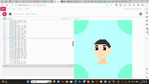
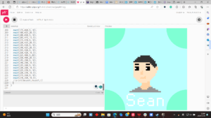
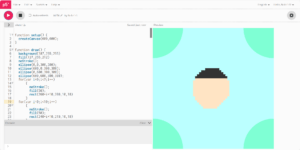
Coding: To draw a pixel selfie, the basic step is to draw the background & decoration patterns and choose the size of a “pixel”, which is a rectangle of 10×10 in this project. Then, using this size of pixel to draw a rough outline.

then, I draw the eyes for this selfie using for loops and dvided colour

then mouse and neck part

finally use a slim black line to go through the sketch of the whole picture and sign the name with pixel style

Code:

function setup() {
  createCanvas(600,600);
}

function draw() {
  background(187,255,255)
  fill(127,255,212)
  noStroke();
  ellipse(0,0,300,300);
  ellipse(600,0,300,300);
  ellipse(0,600,300,300);
  ellipse(600,600,300,300);
  for(var i=0;i<7;i++)
      {
        noStroke();
        fill(50);
        rect(260+i*10,200,10,10)
      }
  for(var i=0;i<10;i++)
      {
        noStroke();
        fill(50);
        rect(240+i*10,210,10,10)
      }
  for(var i=0;i<12;i++)
      {
        noStroke();
        fill(50);
        rect(230+i*10,220,10,10)
      }
  for(var i=0;i<14;i++)
      {
        noStroke();
        fill(50);
        rect(220+i*10,230,10,10)
      }
  for(var i=0;i<16;i++)
      {
        noStroke();
        fill(50);
        rect(210+i*10,240,10,10)
      }
  for(var i=0;i<16;i++)
      {
        noStroke();
        fill(255,228,196);
        rect(210+i*10,250,10,10)
      }
  for (var j=0;j<8;j++)
    {
      for(var i=0;i<18;i++)
      {
        noStroke();
        fill(255,228,196);
        rect(200+i*10,260+j*10,10,10)
      }
    }
  for(var i=0;i<16;i++)
      {
        noStroke();
        fill(255,228,196);
        rect(210+i*10,340,10,10)
      }
  for(var i=0;i<15;i++)
      {
        noStroke();
        fill(255,228,196);
        rect(210+i*10,350,10,10)
      }
  for(var i=0;i<13;i++)
      {
        noStroke();
        fill(255,228,196);
        rect(220+i*10,360,10,10)
      }
  for(var i=0;i<11;i++)
      {
        noStroke();
        fill(255,228,196);
        rect(230+i*10,370,10,10)
      }
  for(var i=0;i<9;i++)
      {
        noStroke();
        fill(255,228,196);
        rect(240+i*10,380,10,10)
      }
  for(var i=0;i<7;i++)
      {
        noStroke();
        fill(255,228,196);
        rect(250+i*10,390,10,10)
      }
  fill(0);
  for(var i=0;i<3;i++){
    rect(220+i*10,260,10,10);
    rect(300+i*10,260,10,10);
    rect(220+i*10,300,10,10);
    rect(300+i*10,300,10,10);
    rect(220+i*10,290,10,10);
    rect(300+i*10,290,10,10);
    rect(220+i*10,280,10,10);
    rect(300+i*10,280,10,10);
  }
  fill(50);
  rect(360,250,10,20);
  rect(370,260,10,10);
  rect(360,270,20,10);
  rect(360,280,10,10);
  rect(330,250,30,10);
  rect(340,260,20,10);
  rect(350,270,10,10);
  fill(255);
  rect(220,290,10,10);
  rect(300,290,10,10);
  fill(187,255,255);
  rect(370,330,10,10);
  rect(200,260,10,80);
  fill(255,228,196)
  rect(380,280,10,30)
  fill(255,210,165);
  rect(270,310,10,30);
  rect(260,320,10,20);
  rect(260,360,40,10);
  rect(290,350,10,10);
  rect(375,285,10,20);
  rect(270,400,40,20);
  rect(260,420,60,10);
  rect(240,430,100,10);
  rect(220,440,140,10);
  rect(310,390,20,40);
  rect(330,420,10,10);
  fill(150);
  rect(240,430,20,10);
  rect(320,430,30,10);
  rect(220,440,50,10);
  rect(310,440,60,10);
  rect(200,450,190,10);
  rect(180,460,230,10);
  fill(255);
  rect(170,480,40,10);
  rect(210,490,10,10);
  rect(160,490,10,30);
  rect(170,520,40,10);
  rect(210,530,10,30);
  rect(170,560,40,10);
  rect(160,550,10,10);
  rect(240,520,10,40);
  rect(250,560,30,10);
  rect(280,550,10,10);
  rect(250,530,40,10);
  rect(250,510,30,10);
  rect(280,520,10,10);
  rect(310,540,10,20);
  rect(320,560,30,10);
  rect(320,530,30,10);
  rect(350,520,10,50);
  rect(320,510,30,10);
  rect(380,510,10,60);
  rect(390,510,30,10);
  rect(420,520,10,50);
  fill(0);
  rect(205,250,5,110);
  rect(210,240,5,10);
  rect(210,240,10,5);
  rect(220,230,5,10);
  rect(220,230,10,5);
  rect(230,220,5,10);
  rect(230,220,10,5);
  rect(240,210,5,10);
  rect(240,210,20,5);
  rect(260,200,5,10);
  rect(260,200,70,5);
  rect(325,200,5,10);
  rect(330,210,10,5);
  rect(335,210,5,10);
  rect(340,220,10,5);
  rect(350,220,5,10);
  rect(355,230,5,10);
  rect(360,240,10,5);
  rect(365,240,5,20);
  rect(370,260,10,5);
  rect(375,260,5,20);
  rect(380,275,10,5);
  rect(390,280,5,30);
  rect(380,310,10,5);
  rect(380,310,5,20);
  rect(370,330,10,5);
  rect(370,330,5,20);
  rect(360,350,10,5);
  rect(360,350,5,10);
  rect(350,360,10,5);
  rect(350,360,5,10);
  rect(340,370,10,5);
  rect(340,370,5,10);
  rect(330,380,10,5);
  rect(330,380,5,40);
  rect(330,415,10,5);
  rect(340,420,5,10);
  rect(340,425,10,5);
  rect(350,430,5,10);
  rect(350,435,20,5);
  rect(370,440,5,10);
  rect(370,445,20,5);
  rect(390,450,5,10);
  rect(390,455,20,5);
  rect(410,460,5,10);
  rect(175,460,5,10);
  rect(180,455,20,5);
  rect(200,450,5,10);
  rect(205,445,15,5);
  rect(215,440,5,10);
  rect(220,435,20,5);
  rect(235,430,5,10);
  rect(240,425,20,5);
  rect(255,420,5,10);
  rect(260,420,10,5);
  rect(265,400,5,20);
  rect(250,400,20,5);
  rect(245,390,5,10);
  rect(240,390,10,5);
  rect(235,380,5,10);
  rect(230,380,10,5);
  rect(225,370,5,10);
  rect(220,370,10,5);
  rect(215,360,5,10);
  rect(210,360,10,5);
  //print(mouseX,mouseY,t)
  
}

Reflection: Sometimes, simple concept such as pixel painting could be as annoying as ordinary art, especially when it comes to figure out exact location for each single pixel. Maybe it’s a good idea to view the problem from the coding perspective rather than the instinct one.

Cyber Boxing-Sean Hu-Eric Parren

1. CONCEPTION AND DESIGN:

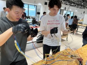
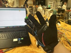
The concept of this project is to build a somatosensory fighting game that integrates all operation systems into a pair of gloves. The inspiration comes from the handles of the VR game set and the WII game set from Nintendo. Both are mature examples of somatosensory games. However, my initial proposal was to build an operating system that required real action from players (i.e.players do really punching for a fighting game) rather than simply pushing buttons on their controller.  My idea was to create an operating system that focused on the movement of the user’s hand and only used buttons and slides as auxiliary means. During user testing, I found the gloves’ sliders are hard to access. Also, the UI part lacks instructions, which makes it hard to understand how to play with it. (photo taken during user testing)

Thus, I made some adjustments to the positions of the buttons to make this project more user-friendly. Also, I polished the UI.

(The final version of the UI)

Those suggestions are pretty helpful for my project since they come from users’ first impressions, which offered me a new version of the project, like UI design.

2. FABRICATION AND PRODUCTION:

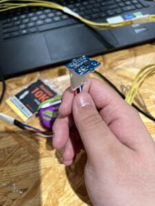
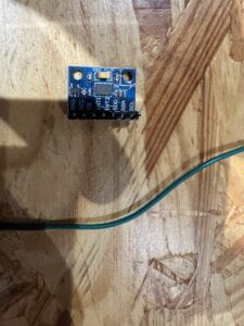
To build this project, I chose two pairs of gloves from Mechanix. The core to detecting the user’s hand movement is using acceleration sensors. Thus, I prepared two kinds of acceleration sensors: ADXL335 and ADXL345.

Due to the limited amount of pins on the Arduino(though it’s a Mega2560), I used two different brands of acceleration sensors for each player. The acceleration sensor is attached to the glove with tape.                                 

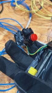
According to the design, this is the only sensor on the right hand. Players could do punches and block defense by punching and blocking. However, due to the difference between different acceleration sensors, the blocking function only works for ADLX345. Therefore, I add a button on one of the player’s operating system for him to do block action.

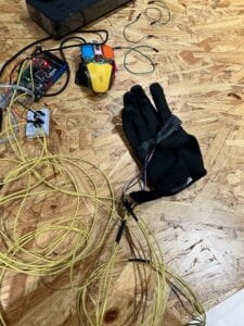
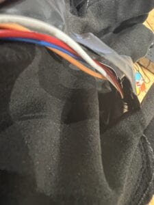
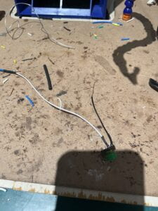
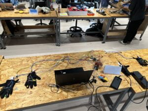
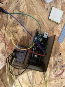
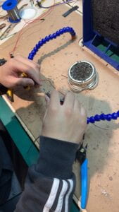
The operating system on the right hand mainly consists of a slider to control the moving action and a button for a kick. Like many games, kicks have a limitation and would cost the skill points in the game. Soon after I finished the first pair of gloves, the Arduino controller easily fell off the table. Considering this, I designed a box to set the Arduino and breadboard and used laser cutting to make it. For the second pair of gloves, the only difference is an extra button on the right hand for blocking. Moreover, I chose to solder the wires and resisters with a longer one to get more space (this is the final outlook of this project)
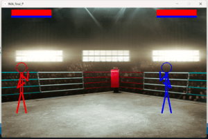
For the UI part, I chose to draw everything in the processing. The first version of the UI only consists of grey in character and red in health present.


an example of the early draft of the UI

However, after the user testing, I did some polishment on the UI to make it more user-friendly

and here’s a video taken for the final version of the project


And here’s the code from Arduino:

#include “ADXL335.h”
ADXL335 accelerometer;
#include <Wire.h>         //调用Arduino自带库
#define Register_ID 0     //器件ID 十六进制为0x00  十进制为0
#define Register_2D 0x2D  //省电特性控制
#define Register_X0 0x32  //X轴数据0
#define Register_X1 0x33  //X轴数据1
#define Register_Y0 0x34  //Y轴数据0
#define Register_Y1 0x35  //Y轴数据1
#define Register_Z0 0x36  //Z轴数据0
#define Register_Z1 0x37  //Z轴数据1
//ADXL345寄存器映射地址
int ADXAddress = 0xA7 >> 1;  // 转换为7位从地址
int reading = 0;
int val = 0;
int X0, X1, X_out;
int Y0, Y1, Y_out;
int Z1, Z0, Z_out;
double Xg, Yg, Zg;
//定义变量
void setup() {
  accelerometer.begin();
  pinMode(2, INPUT);
  pinMode(3, INPUT);
  pinMode(4, INPUT);
  Wire.begin();        //初始化I2C
  Serial.begin(115200);  //初始化串口
  delay(100);
  // enable to measute g data
  Wire.beginTransmission(ADXAddress);  //开启发送
  Wire.write(Register_2D);             //写入ADXL345寄存器映射地址
  Wire.write(8);                       //测量使能
  Wire.endTransmission();              // 停止发送
}
void loop() {
  int d1 = digitalRead(2);
  int d2 = digitalRead(3);
  int d3 = digitalRead(4);
  int p1 = analogRead(A8);
  int p2 = analogRead(A9);
  //读取X轴数据
  Wire.beginTransmission(ADXAddress);  // 开启发送
  Wire.write(Register_X0);             //写入ADXL345寄存器映射地址
  Wire.write(Register_X1);             //写入ADXL345寄存器映射地址
  Wire.endTransmission();              //结束发送
  Wire.requestFrom(ADXAddress, 2);     //请求 ADXL345 二个字节
  if (Wire.available() <= 2)           //获取<=2个数据
  {
    X0 = Wire.read();
    X1 = Wire.read();
    X1 = X1 << 8;
    X_out = X0 + X1;
  }
  //读取Y轴数据↓
  Wire.beginTransmission(ADXAddress);  // 开启发送
  Wire.write(Register_Y0);             //写入ADXL345寄存器映射地址
  Wire.write(Register_Y1);             //写入ADXL345寄存器映射地址
  Wire.endTransmission();              //结束发送
  Wire.requestFrom(ADXAddress, 2);     //请求ADXL345二个字节
  if (Wire.available() <= 2)           //获取<=2个数据
  {
    Y0 = Wire.read();
    Y1 = Wire.read();
    Y1 = Y1 << 8;
    Y_out = Y0 + Y1;
  }
  //读取Z轴数据
  Wire.beginTransmission(ADXAddress);  // 开启发送
  Wire.write(Register_Z0);             //写入ADXL345寄存器映射地址
  Wire.write(Register_Z1);             //写入ADXL345寄存器映射地址
  Wire.endTransmission();              //结束发送
  Wire.requestFrom(ADXAddress, 2);     //请求ADXL345二个字节
  if (Wire.available() <= 2)           //获取<=2个数据
  {
    Z0 = Wire.read();
    Z1 = Wire.read();
    Z1 = Z1 << 8;
    Z_out = Z0 + Z1;
  }
  float x;
  float y;
  float z;
  accelerometer.getAcceleration(&x, &y, &z);
  Xg = X_out;
  Yg = Y_out;
  Zg = Z_out;
  Serial.print(Xg);
  Serial.print(“,”);
  Serial.print(Yg);
  Serial.print(“,”);
  Serial.print(Zg);
  Serial.print(“,”);
  Serial.print(p1);
  Serial.print(“,”);
  Serial.print(d1);
  Serial.print(“,”);
  Serial.print(x);
  Serial.print(“,”);
  Serial.print(y);
  Serial.print(“,”);
  Serial.print(z);
  Serial.print(“,”);
  Serial.print(d2);
  Serial.print(“,”);
  Serial.print(p2);
  Serial.print(“,”);
  Serial.print(d3);
  Serial.println();
  delay(10);
  //串口输出
}
And here’s the code from Processing:
import processing.serial.*;
PImage photo;
Serial serialPort;
float edge1= 200.0;
int NUM_OF_VALUES_FROM_ARDUINO = 11;  /* CHANGE THIS ACCORDING TO YOUR PROJECT */
float p1=100;
float p2=924;
/* This array stores values from Arduino */
float arduino_values[] = new float[NUM_OF_VALUES_FROM_ARDUINO];
boolean x1=false;
boolean y1=false;
boolean z1=false;
int fist1=0;
int leg1=0;
int fist2=0;
int leg2=0;
float hp1=100.0;
float hp2=100.0;
float mp1=100.0;
float mp2=100.0;
void setup() {
  size(1024, 650);
  photo = loadImage("B1.jpg");
  printArray(Serial.list());
  // put the name of the serial port your Arduino is connected
  // to in the line below - this should be the same as you're
  // using in the "Port" menu in the Arduino IDE
  serialPort = new Serial(this, "COM3", 115200);
  getSerialData();
}

int time1 = 0;
int Ptime1=0;
int time2 = 0;
int Ptime2=0;
void draw() {
  text("Player1: right hand forward:punch,right hand upward:block, red button: kick,slider: movement", 48, 180, -120);
  int Pleg1=leg1;
  int Pleg2=leg2;
  int Pfist1=fist1;
  int Pfist2=fist2;
  background(arduino_values[3]);
  if (map(arduino_values[3], 0, 350, 0, 700)+100<924-map(arduino_values[9], 0, 350, 0, 700)-100) {
    p1=map(arduino_values[3], 0, 350, 0, 700)+100;
    p2=924-map(arduino_values[9], 0, 350, 0, 700)-100;
  }
  background(0);
  image(photo, 0, 0);
  float px=arduino_values[0];
  float py=arduino_values[1];
  float pz=arduino_values[2];
  float px2=arduino_values[5];
  float py2=arduino_values[6];
  float pz2=arduino_values[7];
  //receive the values from Arduino
  getSerialData();
  float x=arduino_values[0];
  float y=arduino_values[1];
  float z=arduino_values[2];
  float x2=arduino_values[5];
  float y2=arduino_values[6];
  float z2=arduino_values[7];
  if (abs(x-px)>edge1) {
    x1=true;
  } else x1=false;
  if (abs(y-py)>edge1) {
    y1=true;
  } else y1=false;
  if (abs(z-pz)>edge1) {
    z1=true;
  } else z1=false;
  if (arduino_values[4]==1&&mp1>0) {
    leg1=1;
    if (Pleg1==0)
      mp1-=30;
  } else leg1=0;
  if (arduino_values[10]==1&&mp2>0) {
    leg2=1;
    if (Pleg2==0)
      mp2-=30;
  } else leg2=0;
  if (z-pz>250  &&x-px<edge1&&mp1>0) {
    Ptime1=millis();
    fist1=2;
    //mp1-=5;
  } else {
    time1=millis();
    if (time1-Ptime1>100)
      fist1=0;
  }
  //println(x1,y1,z1);
  if (x-px>edge1) {
    Ptime1=millis();
    fist1=1;
  } else {
    time1=millis();
    if (time1-Ptime1>100)
      fist1=0;
  }
  if (arduino_values[8]==1&&mp2>0)
  {
    fist2=2;
    mp2-=5;
  } else {
    if ((px2-x2)>1.5) {
      Ptime2=millis();
      fist2=1;
    } else
    {
      time2=millis();
      if (time2-Ptime2>100)
        fist2=0;
    }
  }
  if (abs(p1-p2)<150)
  {
    if (fist1==1 && fist2!=2&&Pfist1!=1)
      hp2-=5;
    if (fist2==1&&fist1!=2&&Pfist2!=1)
      hp1-=5;
    if (leg1==1&&Pleg1!=1)
      hp2-=20;
    if (leg2==1&&Pleg2!=1)
      hp1-=20;
  }
  if (hp1>0&&hp2>0) {
    drawPlayer1();
    drawPlayer2();
    strokeWeight(0);
    rect(0, 0, 50, 50);
    rect(974, 0, 50, 50);
    fill(255, 0, 0);
    rect(50, 10, hp1*2, 30);
    rect(974-hp2*2, 10, hp2*2, 30);
    fill(0, 0, 255);
    rect(50, 40, mp1*2, 10);
    rect(974-mp2*2, 40, mp2*2, 10);
    //text("Player1: right hand forward:punch,right hand upward:block, red button: kick,slider: movement", 48, 200);
    //text("Player2: right hand forward:punch,right hand button:block, left button: kick,slider: movement", 48, 250);
    noFill();
    //print(p1,p2);
    //delay(10);
    if(mp1<=100)
    mp1+=0.05;
    if(mp2<=100)
    mp2+=0.05;
  }
  if (hp1<=0&&hp2>0)
  {
    textSize(128);
    fill(0, 408, 612, 816);
    text("Player2 Win", 48, 180, -120);
  }
  if (hp2<=0&&hp1>0)
  {
    textSize(128);
    fill(0, 408, 612, 816);
    text("Player1 Win", 48, 180, -120);
  }
}
void drawBody1() {
  stroke(255, 0, 0);
  strokeWeight(3);
  circle(p1, 300, 50);
  strokeWeight(5);
  rect(p1-5, 325, 10, 100);
  if (leg1==0) {
    strokeWeight(7);
    line(p1-3, 425, p1-23, 525);
    line(p1+3, 425, p1+23, 525);
  }
  if (leg1==1) {
    strokeWeight(7);
    line(p1+3, 425, p1+10, 475);
    line(p1+10, 475, p1+3, 525);
    line(p1, 425, p1+45, 415);
    line(p1+45, 415, p1+90, 425);
  }
}
void drawPlayer1() {
  if (fist1==0) {
    stroke(255, 0, 0);
    strokeWeight(7);
    line(p1, 335, p1-20, 400);
    line(p1-20, 400, p1+15, 375);
    drawBody1();
    line(p1, 335, p1+30, 365);
    line(p1+30, 365, p1+32.5, 320);
    return;
  }
  if (fist1==1) {
    stroke(255, 0, 0);
    strokeWeight(7);
    line(p1, 335, p1-20, 400);
    line(p1-20, 400, p1+15, 375);
    drawBody1();
    line(p1, 335, p1+100, 335);
    //delay(50);
    return;
  }
  if (fist1==2)
  {
    drawBody1();
    line(p1, 335, p1+30, 365);
    line(p1+30, 365, p1+32.5, 320);
    line(p1, 335, p1+25, 375);
    line(p1+25, 375, p1+27.5, 335);
    return;
  }
}
void drawPlayer2() {
  if (fist2==0) {
    stroke(0, 0, 255);
    strokeWeight(7);
    line(p2, 335, p2+20, 400);
    line(p2+20, 400, p2-15, 375);
    drawBody2();
    line(p2, 335, p2-30, 365);
    line(p2-30, 365, p2-32.5, 320);
    return;
  }
  if (fist2==1) {
    stroke(0, 0, 255);
    strokeWeight(7);
    line(p2, 335, p2+20, 400);
    line(p2+20, 400, p2-15, 375);
    drawBody2();
    line(p2, 335, p2-100, 335);
    //delay(50);
    return;
  }
  if (fist2==2)
  {
    drawBody2();
    line(p2, 335, p2-30, 365);
    line(p2-30, 365, p2-32.5, 320);
    line(p2, 335, p2-25, 375);
    line(p2-25, 375, p2-27.5, 335);
    return;
  }
}
void drawBody2() {
  stroke(0, 0, 255);
  strokeWeight(3);
  circle(p2, 300, 50);
  strokeWeight(5);
  rect(p2-5, 325, 10, 100);
  if (leg2==0) {
    strokeWeight(7);
    line(p2-3, 425, p2-23, 525);
    line(p2+3, 425, p2+23, 525);
  }
  if (leg2==1) {
    strokeWeight(7);
    line(p2-3, 425, p2-10, 475);
    line(p2-10, 475, p2-3, 525);
    line(p2, 425, p2-45, 415);
    line(p2-45, 415, p2-90, 425);
  }
}

// the helper function below receives the values from Arduino
// in the "arduino_values" array from a connected Arduino
// running the "serial_AtoP_arduino" sketch
// (You won't need to change this code.)

void getSerialData() {
  while (serialPort.available() > 0) {
    String in = serialPort.readStringUntil( 10 );  // 10 = '\n'  Linefeed in ASCII
    if (in != null) {
      print("From Arduino: " + in);
      String[] serialInArray = split(trim(in), ",");
      if (serialInArray.length == NUM_OF_VALUES_FROM_ARDUINO) {
        for (int i=0; i<serialInArray.length; i++) {
          arduino_values[i] = float(serialInArray[i]);
        }
      } else {
        println("Serial comm error");
      }
    }
  }
}

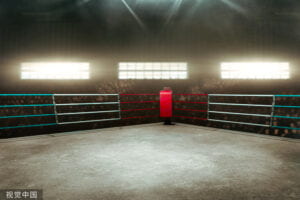
Also, here’s the background picture of my project from Version China(视觉中国—正版高清图片、视频、音乐、字体下载—商业图片下载网站 (vcg.com))
 
3. CONCLUSIONS:
The goal of this project was to explore a new way of interaction for fighting games. Eventually, this project developed into a combination of a Gamepad and Nintendo Wii controller.  However, the primary operation for this game(punching) is still conducted by users” Real punching and buttons here are no longer the leading interaction players have with the game. Most players have shown their strong interest in this project during the user testing and IMA show. If I had more time to polish this, I would pay more attention to the UI design and game logic. Also, I would try to replace the buttons with different gestures. The most valuable lesson I learned from this project is that one should have a clear understanding of how difficult a task could be and where’s the edge of ability. I choose to do the final solo for more flexible working hours. However, I misjudged the labor this project required and got torched by that. A clear understanding could be pretty significant for a well-organized project schedule.

4. APPENDIX

the video for the laser cutting process:

The video of how the left-hand part looks like after putting on the gloves:


Carrier Assistant-Yuquan Hu-Eric Parren

1. context and significance

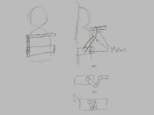
Before the project started, we searched for projects sharing the same idea with others, but only found nearly no responses. Also, the former group project didn’t give us much inspiration.  Though, the progress of the group project does teach me some quite significant lessons:1. the idea of having a portable carrying platform could be pretty helpful for those who are trying to conduct some handicraft work in a limited room with only a few tables accessible. Thus, the “carrier assistant” project, interactively speaking, must be portable, and wearable specifically speaking. Moreover, the awful experience I had with cardboard makes them material with terrible strength and stability. Thus, in our project plan, the system shall be fixed and `integrated on a wist to make it portable and wearable, also we need to make the frame with much stronger material to make it stable. Following is the sketch

2. conception and design

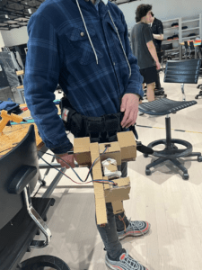
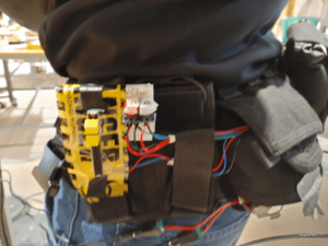
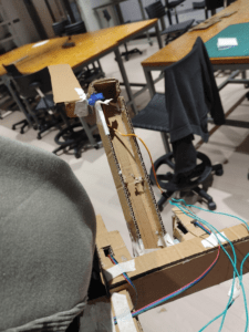
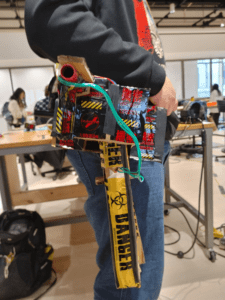
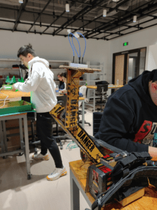
For interactive design, we chose to set up the system on a tactical wist and have all the circuits and wires packed. The mechanical arm would lay on the right side while the controller will be on the left side of the system. The controller will consist of two parts: a set of buttons to control the main arm and a slider to control the carriage platform. The main body  of the arm is made of cardboard, while the frame that attaches the system and the wist is supported by two metal tube

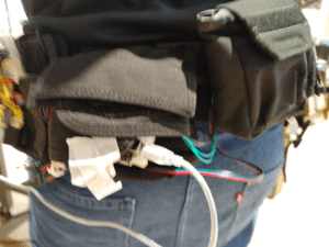
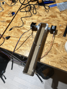
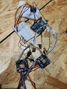
The system is driven by two stepper motors which are powered by 12V DC. For the circuit and wire, we chose to have them packed in the packs on the wist.

for the alternative material. I once tried to use the metal tube to replace the cardboard of the arm part, but that’s too heavy to have the stepper motors to carry them. Also, we once tried to add a secondary arm for the system, which eventually got abolished due to the poor power of the stepper motors.

3. fabrication and production

For the first step, we tried to build the system separately from the wist. Meanwhile, I set up the circuit for the stepper motors

we tried to use only one stepper motor at first, but it turned out to be too weak for this tusk. So we switched to the 2 motors version.

Later, we built the rest covering frame for the arm and had phased testing.

Then we connected the system to the waist and tried to build the secondary arm, however, such a design turned out to be too hard to carry out by the stepper motors.

As what showed in this video, the arm itself is the maxim weight that it could take. Obviously, we want more than that. So we directly chose to use only two arms and append a slider for the controller


During the user testing, we received several comments,  focusing on 1. completing the mechanism arm 2: adding more instructions 3: restricting the angle of the arm. 3. make the waist more balanced. 4. put all the circuits inside the waist straps.

after polishing the system by re-design the platform for carriage, fixing the cod,e and adding more blocks to make the system more balanced, we also add some decorations to the system.


During the process, I did most of the coding and circuit-building jobs, while my partner did most of the handicraft and structure-building jobs. The way we corporate was that I describe the idea for the whole project and he developed a more specific thought on the frame while I start to work with the electronics 

Also, here’s the code.

#include <AccelStepper.h>

#include <Servo.h>

int cnt=0;

int DIR_PIN = 2;

int STEP_PIN = 3;

int EN_PIN = 4;

int DIR_PIN2 = 5;

int STEP_PIN2 = 6;

int EN_PIN2 = 7;

Servo servo1;

Servo servo2;

AccelStepper stepper(AccelStepper::DRIVER, STEP_PIN, DIR_PIN);

AccelStepper stepper2(AccelStepper::DRIVER, STEP_PIN2, DIR_PIN2);


void setup() {

Serial.begin(9600);

servo1.attach(9);

servo2.attach(10);

pinMode(13,INPUT);

pinMode(12,INPUT);

// Enable the stepper driver

pinMode(EN_PIN, OUTPUT);

digitalWrite(EN_PIN, LOW);

pinMode(EN_PIN2, OUTPUT);

digitalWrite(EN_PIN2, LOW);

// Set initial speed & acceleration

stepper.setMaxSpeed(1000);

stepper.setAcceleration(500);

stepper2.setMaxSpeed(1000);

stepper2.setAcceleration(500);

servo1.write(10);

servo2.write(0);

}

void loop() {

int input_slide=analogRead(A0);

int input1=digitalRead(13);

int input2=digitalRead(12);

if (input1==0&&input2==0){

stepper.stop();

stepper2.stop();

 }

if (input1==1&&input2==0&&cnt<=0) {

cnt++;

}

if (input1==0&&input2==1&&cnt>=-90){

cnt–;

}

Serial.println(cnt);

stepper.moveTo(cnt);

stepper2.moveTo(-cnt);

stepper.setSpeed(50);

stepper2.setSpeed(50);

stepper.runSpeedToPosition();

stepper2.runSpeedToPosition();

int servo_angle2=map(input_slide,0,1023,0,180);

servo2.write(servo_angle2)

}

4. Conclusion

The aim of this project is to provide a portable system that could help to carry items when there are no tables or hands available. The final prototype is wearable and also has enough power to carry certain items. The problems mainly lay in the power problem. The system won’t be truly portable unless we make the power pack portable. Also, the system needs a better way of interaction. The current system is designed for people with a body figure like me. Also, the controller needs a more intuitive way to show the angle and degree. However, the system still plays an interactive role by functioning as the extent of the human body. What I’ve learned is that all plans may somehow encounter various kinds of failures, so maybe a plan B is not always enough, and a plan C can be sometimes life-saving.


Group project Mirror

  1. Ideas&buliding

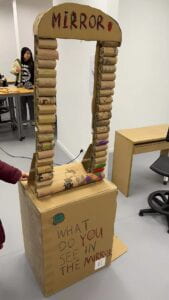
At the begining of the group meeting we chatted for several ideas like a big nursing  goose robot to armed reomte control car. Eventually for the project we come up with the idea of a special mirror that will gradually turned the reflection inside into the scene of that locked kid in the story “Th ones who walk away from Omelas “. In the novel omelas is a utopian city which based on a suffered kid. Though the citizens of Omelas have all seen that kids, few of them thought that it may have also happened to them, such that , a machine that indicate this may be significant to morality.

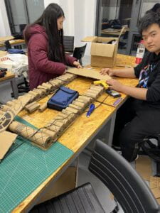
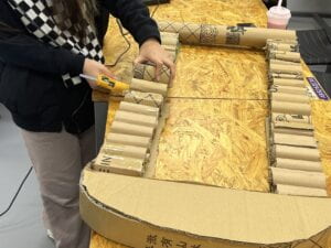
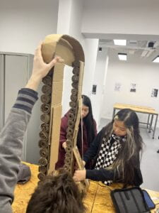
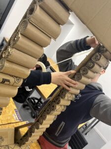
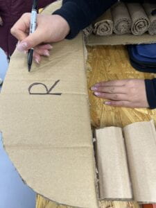
we been using the card board to bulid the frame of the mirror. However, we then found it hard to make it stand. To deal with it this problem we tried different materials and determined to use a triangle made by cardborad and tape to stick it.

For the last step, we have some decorations on the mirror by markers

2. performance

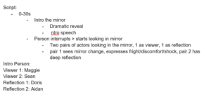
For performance part we made a simplke script: The mirror was carried with an outsider who seen the sin and darkness of omelas. Two citizen would have visit the mirror. One will get scared by the mirror and another will make a self-reflection on the city itself and eventually decided to leave it.

In the script on group member will be the outsider and others will be in pairs to act as the viewer and reflection

And that has been the final performance

3. Other group’s performance

In my perspective of view, the one impressed me most is the TV one, which assumed a TV with the same tech that used in the nurse room. It’s quite a good performance by acting the TV offering whatever the user want. But what impressed me most was that this project is not come from nowhere but a modified version of the tech existing in the article. This article extended the origin article with quite an arduino way-using what exists now. Thus I found this a great project that can be  learned with. However, I still suggest them to pay a bit focus on the explanation of limation and restriction on the machine.


Hello world!

Welcome to Web Publishing @ NYU. This is your first post. Edit or delete it, then start creating your site!

Online help is available via the Web Publishing Knowledge Site (wp.nyu.edu/knowledge) and the ServiceLink knowledge base (www.nyu.edu/servicelink). Through ServiceLink, you can find step-by-step instructions, as well as tutorials.

Digital Accessibility

As content creators who create and publish text, images, video, and audio, you must adhere to the NYU Website Accessibility Policy (https://www.nyu.edu/digitalaccessibility/policy) when creating and publishing digital content.

Web Publishing-specific Digital Accessibility Best Practices and examples of how to ensure your content are compliant are available at https://wp.nyu.edu/digitalaccessibility

If you have additional questions, contact the IT Service Desk for assistance. Support is available 24/7/365. For more details, visit www.nyu.edu/it/servicedesk.