1. context and significance
Before the project started, we searched for projects sharing the same idea with others, but only found nearly no responses. Also, the former group project didn’t give us much inspiration. Though, the progress of the group project does teach me some quite significant lessons:1. the idea of having a portable carrying platform could be pretty helpful for those who are trying to conduct some handicraft work in a limited room with only a few tables accessible. Thus, the “carrier assistant” project, interactively speaking, must be portable, and wearable specifically speaking. Moreover, the awful experience I had with cardboard makes them material with terrible strength and stability. Thus, in our project plan, the system shall be fixed and `integrated on a wist to make it portable and wearable, also we need to make the frame with much stronger material to make it stable. Following is the sketch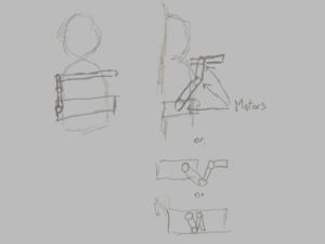
2. conception and design
For interactive design, we chose to set up the system on a tactical wist and have all the circuits and wires packed. The mechanical arm would lay on the right side while the controller will be on the left side of the system. The controller will consist of two parts: a set of buttons to control the main arm and a slider to control the carriage platform. The main body of the arm is made of cardboard, while the frame that attaches the system and the wist is supported by two metal tube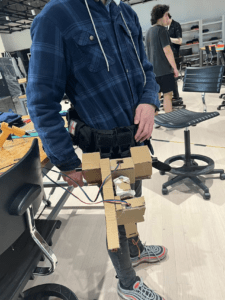
The system is driven by two stepper motors which are powered by 12V DC. For the circuit and wire, we chose to have them packed in the packs on the wist. 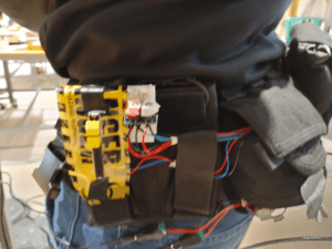
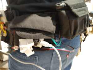
for the alternative material. I once tried to use the metal tube to replace the cardboard of the arm part, but that’s too heavy to have the stepper motors to carry them. Also, we once tried to add a secondary arm for the system, which eventually got abolished due to the poor power of the stepper motors.
3. fabrication and production
For the first step, we tried to build the system separately from the wist. Meanwhile, I set up the circuit for the stepper motors 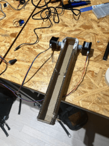
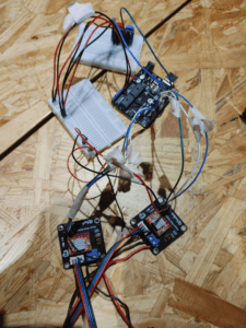
we tried to use only one stepper motor at first, but it turned out to be too weak for this tusk. So we switched to the 2 motors version.
Later, we built the rest covering frame for the arm and had phased testing.
Then we connected the system to the waist and tried to build the secondary arm, however, such a design turned out to be too hard to carry out by the stepper motors.
As what showed in this video, the arm itself is the maxim weight that it could take. Obviously, we want more than that. So we directly chose to use only two arms and append a slider for the controller
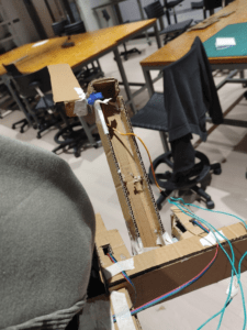
During the user testing, we received several comments, focusing on 1. completing the mechanism arm 2: adding more instructions 3: restricting the angle of the arm. 3. make the waist more balanced. 4. put all the circuits inside the waist straps.
after polishing the system by re-design the platform for carriage, fixing the cod,e and adding more blocks to make the system more balanced, we also add some decorations to the system.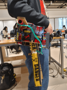
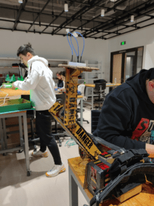
During the process, I did most of the coding and circuit-building jobs, while my partner did most of the handicraft and structure-building jobs. The way we corporate was that I describe the idea for the whole project and he developed a more specific thought on the frame while I start to work with the electronics
Also, here’s the code.
#include <AccelStepper.h>
#include <Servo.h>
int cnt=0;
int DIR_PIN = 2;
int STEP_PIN = 3;
int EN_PIN = 4;
int DIR_PIN2 = 5;
int STEP_PIN2 = 6;
int EN_PIN2 = 7;
Servo servo1;
Servo servo2;
AccelStepper stepper(AccelStepper::DRIVER, STEP_PIN, DIR_PIN);
AccelStepper stepper2(AccelStepper::DRIVER, STEP_PIN2, DIR_PIN2);
void setup() {
Serial.begin(9600);
servo1.attach(9);
servo2.attach(10);
pinMode(13,INPUT);
pinMode(12,INPUT);
// Enable the stepper driver
pinMode(EN_PIN, OUTPUT);
digitalWrite(EN_PIN, LOW);
pinMode(EN_PIN2, OUTPUT);
digitalWrite(EN_PIN2, LOW);
// Set initial speed & acceleration
stepper.setMaxSpeed(1000);
stepper.setAcceleration(500);
stepper2.setMaxSpeed(1000);
stepper2.setAcceleration(500);
servo1.write(–10);
servo2.write(0);
}
void loop() {
int input_slide=analogRead(A0);
int input1=digitalRead(13);
int input2=digitalRead(12);
if (input1==0&&input2==0){
stepper.stop();
stepper2.stop();
}
if (input1==1&&input2==0&&cnt<=0) {
cnt++;
}
if (input1==0&&input2==1&&cnt>=-90){
cnt–;
}
Serial.println(cnt);
stepper.moveTo(cnt);
stepper2.moveTo(-cnt);
stepper.setSpeed(50);
stepper2.setSpeed(50);
stepper.runSpeedToPosition();
stepper2.runSpeedToPosition();
int servo_angle2=map(input_slide,0,1023,0,180);
servo2.write(servo_angle2);
}
4. Conclusion
The aim of this project is to provide a portable system that could help to carry items when there are no tables or hands available. The final prototype is wearable and also has enough power to carry certain items. The problems mainly lay in the power problem. The system won’t be truly portable unless we make the power pack portable. Also, the system needs a better way of interaction. The current system is designed for people with a body figure like me. Also, the controller needs a more intuitive way to show the angle and degree. However, the system still plays an interactive role by functioning as the extent of the human body. What I’ve learned is that all plans may somehow encounter various kinds of failures, so maybe a plan B is not always enough, and a plan C can be sometimes life-saving.