The Tree of Fate – Savanna Peng – Andy Garcia
Context & Significance
Comparing our project to one of the other interaction projects that I have researched previously in this class, I can draw connections between our user-testing version of the project and the glass door that has a pull handle but is supposed to be pushed. From the user testing session, many of our players didn’t understand to pluck the flowers instead of catching the flowers when they fell. This relates to the misleading door handle as both send mixed signals to the audience which can direct them to respond to the project in a way that they aren’t supposed to. The parallel between these two design errors triggered my understanding of interaction in a deeper way as I now understand how interaction can be straightforward to the designers but not the audience, and that the goal of interaction is to be able to deliver the correct message to the player in the most simple and effective form.
One thing that marks our project apart from the others we saw in class is that it is one of the few interaction art pieces, instead of interaction games, and that also portrays a message behind it. Taking inspiration from Sylvia Plath’s famous passage about a fig tree, our project delivers a message to not be greedy when making decisions in life and to make swift decisions before they all slip away. Though these interactive art pieces did not exist previously, our take on this project’s inspiration, the fig tree passage, was to simplify the numerous fate choices into just five choices and to showcase them as flowers instead of figs. We made these decisions to simplify the interaction process, and because we thought that this would match our standards of aesthetics better. In the development process of this project, my contributions were on the technical side: coding and wiring. The intended audience of this project could be Sylvia Plath fans/readers as it is a physical project of a metaphor that she includes in her writings, or just anyone who finds this project visually appealing.
Conception & Design
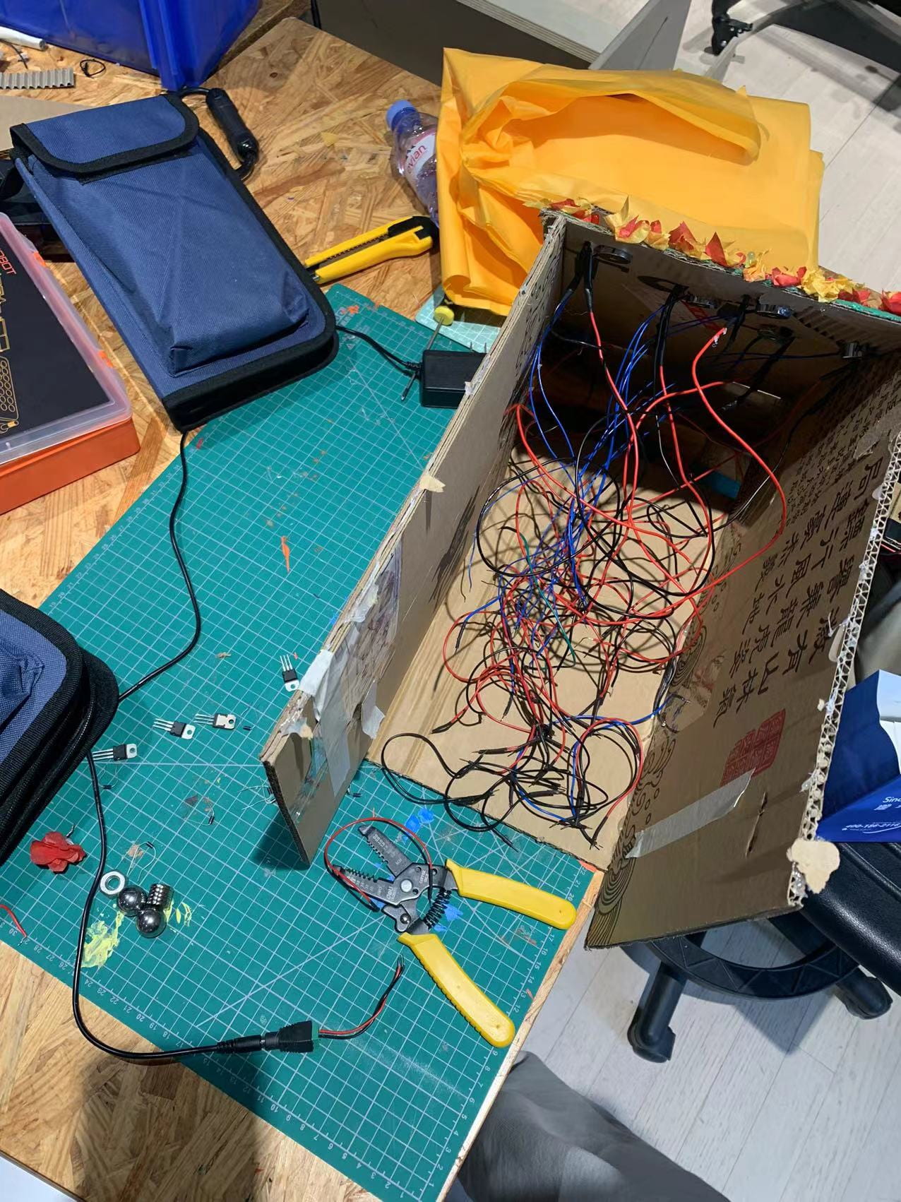
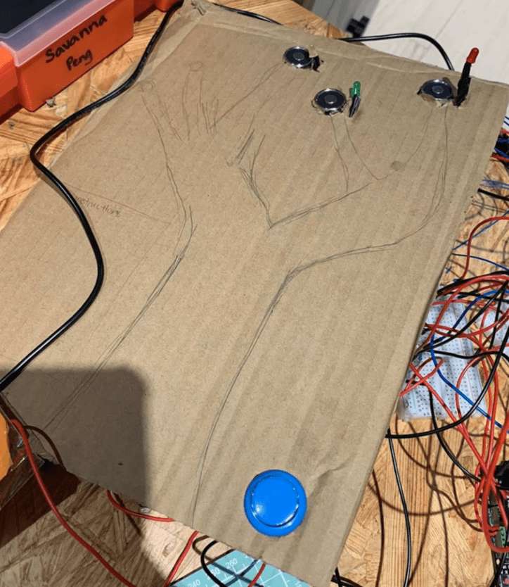
My understanding of how the users were going to choose their fate was by simply pulling the flowers off the board, hence why we made the flower stems longer to stick out of the board and also included the word “pluck” in the instructions. I also wanted a “formal” way to begin the interaction and my understanding of how my users would react to a button fit this criteria the best, in comparison to any other reaction-documenting mechanism, like a slider. One major change that we enacted after beginning to build this project was changing the tree from 3D to 2D. At first, we wished to build a 3D model of the tree with cardboard and wooden dowels. However, after receiving feedback and further consideration of where the wires would go and how stable this tree would be, we decided to make this tree on a board/front of a box and hide all the wires behind the board within the box.
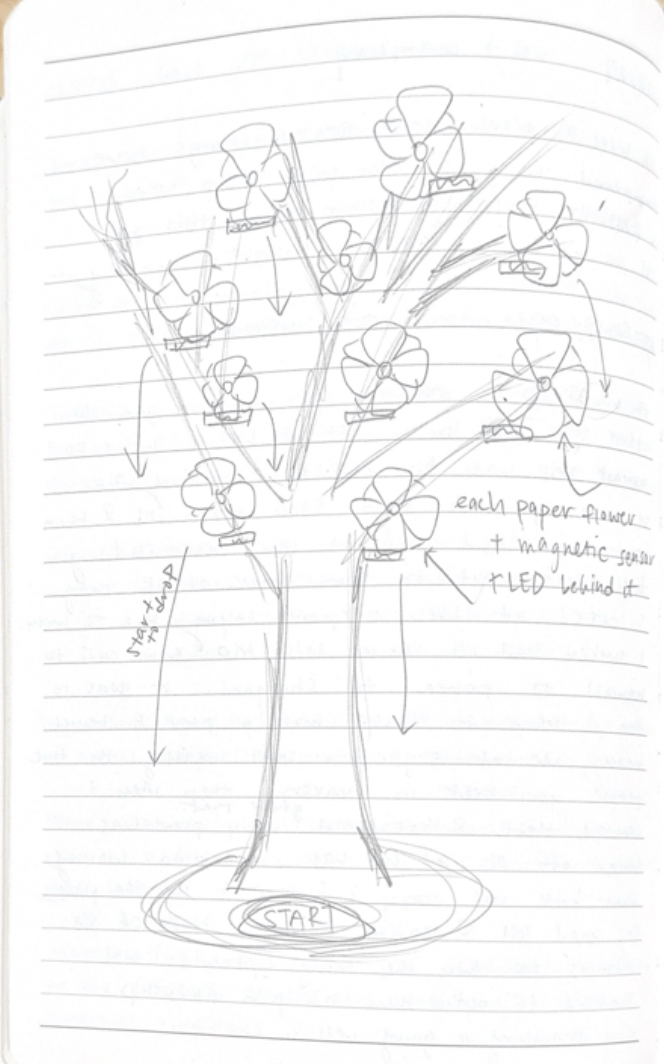
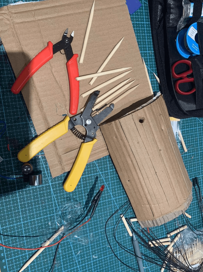
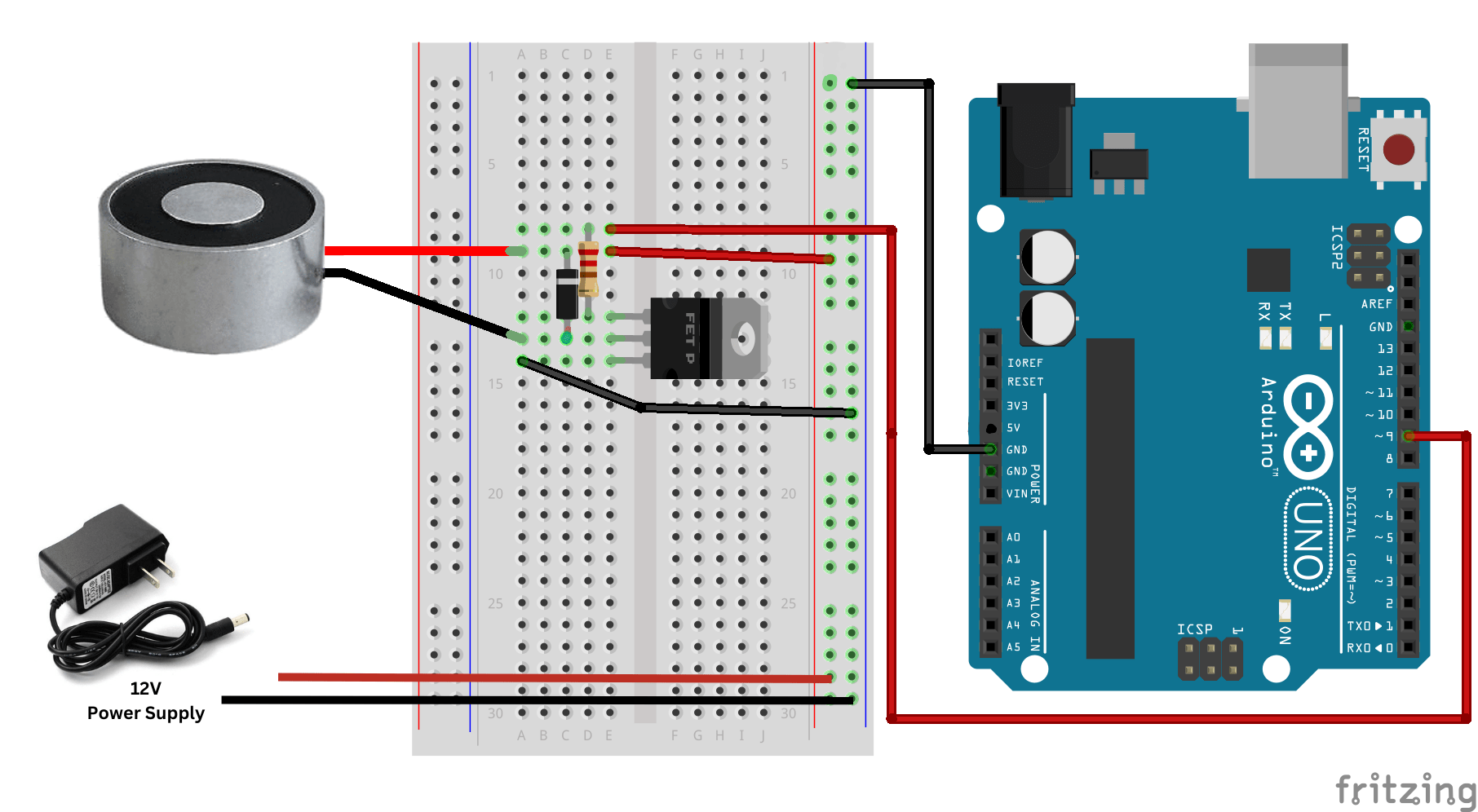
The first form we decided to use was electromagnetic sensors when brainstorming this project because its ons and offs are easy to control with code while also the flower on top can be “forcefully” pulled off even when the magnet is still on. Next, we decided to add LEDs behind every flower to make the five flower choices stand out more and act as a visual guide of whether or not the choices are still available. We decided to use tissue paper to make the flower petals as it is light, pretty, and thin, allowing the LEDs to shine through. We initially wanted to use the bottom of plastic bottles for the flower petals as it is clear and already resemble the shape of a flower. However, we opted for tissue paper because we considered that plastic might be too heavy.
Fabrication & Production
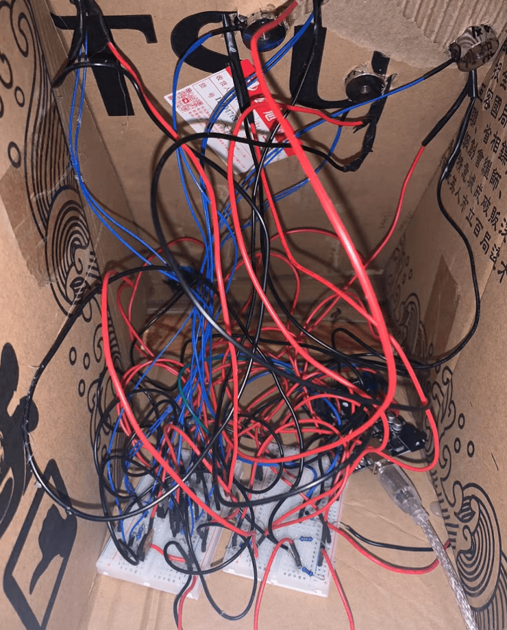
One of the most significant steps in my production process that led to many failures and successes was keeping track of pin numbers. My project had many circuits and it eventually became confusing to dig through piles of wires to figure out what pin connects to which wire and sensor or LED. Ensuring that there is a clear record as to which sensor and LED corresponds to which pin number and also keeping consistency with that while coding and developing the project would have saved me much more time and frustration. Wiring soldering was a new skill I developed while doing this project as I have only had one experience with this prior. After soldering wires, I learned that it is crucial to wrap electrical tape around the exposed wires to not cause a short circuit. We caused a short circuit in an LED on the first day, which broke the LED in half. My partner also soldered the positive and negative sides wrong, which was a pain to figure out after the wires were wrapped in tape and a lesson for us to pay closer attention to the positives and negatives before doing anything.
Developing the code was probably the most difficult part of the project as I am completely unfamiliar with coding. One thing that helped so much with the organization of both the code and my understanding of the logic behind the code was separating the code into different stages. For example, having this
 if (stage == 0) {
    startButtonState = digitalRead(buttonPin);
    if (startButtonState == 1) {
      Serial.println("Pressed");
      startTime = millis();
      stage = 1;
    }
instead of this
// Serial.print("Released after ");
    //Serial.println(millis() - startTime);

    //digitalWrite(electroMagnetPin1, HIGH);  //Switch Electromagnet ON=

    //buttonState1 = digitalRead(2);
    //Serial.println(buttonState1);

    //if (buttonState1 == HIGH) {
    //digitalWrite(ledPin1, HIGH);

    //}

    // delay(10000);

    // digitalWrite(electroMagnetPin1, LOW);  //Switch Electromagnet OFF
    // buttonState1 = digitalRead(7);
    // Serial.println(buttonState1);

    // if (buttonState1 != HIGH) {
    //   digitalWrite(ledPin1, LOW);
    // }
Separating the code into different stages helped me to see clearly which part of the code is the “if” and what are the results and/or “elses” that come from the different reactions that the audience could give. It also helped a lot to divide stage 0 with the rest of the stages to set up the code and program before actually running anything, which contributes to what I mentioned above about knowing which pin matches which sensor or LED.
The way that my partner and I split up the work for this project was that I did the coding and wiring and she did the physical arts and building. As I do not know much about wiring and coding, this project was a challenge and a huge learning process for me but thankfully I figured it out with the help of learning assistants and professors. When I was done editing the code after every work session, I would message the code to my partner and give her a to-do list for when she came into the studio. During user testing, we found that our project still had a lot to develop as the instructions/message was unclear and that the project itself needed improvement on the visual aesthetics. After this session, we added blinks to the LED, randomized in the timing of which flower would fall first, and clarified the instructions poem by adding specific words like “pluck” and “only one flower”. I added blinking to the LED lights after the start button is pressed to indicate that the clock is ticking because, after user-testing, I understood that users did not feel an urgency to react after pressing the start button. Before having this LED blink, it was ambiguous that there isn’t an unlimited amount of time to make your decision. We also found that our users were confused as to what to do with the flowers and eventually began to discover the order of the flowers falling. Additionally, I created a box that stuck to the board for stability and to hide the wires and added a front panel to catch the flowers that were initially falling onto the floor as the board itself was not stable, there were lots of wires exposed to the audience, and that it was a hassle to catch/pick up the flowers every time they fell.
Conclusions
The goals of this project are to create a visually aesthetic interactive art piece and deliver a similar message to what Sylvia Plath delivered in her book, which is to make your decisions in a timely and “grateful” manner. Our project aligns with my definition of interaction as it encourages communication and delivers messages between the audience and the project. However, it doesn’t align with my definition of interaction enough as the message could be confusing or easily misinterpreted by some people, and the interaction might have been too short as it is a one-time decision. Ultimately, my audience didn’t respond to my project in the exact manner that I expected: some were trying to catch the flowers from falling, some didn’t read the instructions carefully before beginning, and some didn’t know to place the flowers into the “place here” box, etc. If I had all the time in the world to work on this project, some improvements I would implement are adding many more flowers and LEDs to increase the number of choices available, making the “place here” box more dramatic and eye-catching, adding sound effects to indicate the timer and wins/losses, and adding LEDs around each flower to show which fate the user ends up with if they successfully choose and place that one into the box.
From all of the setbacks and failures that I have encountered during this project, I believe the biggest value I learned from this is that projects like these take lots of planning and patience. At first, our ideas weren’t realistic (at least for our skill level) and we had to quickly simplify our plans so that we could implement them. I also learned that for these projects to work, lots of patience is required in each part of the process. Thankfully, in the end, this project turned out successfully and people were able to interact with it the way that we planned (kind of, I hope).
Final code:
//boolean gameStart = false;
int stage = 0;
//led and magnet 1
int ledPin1 = 13;
int electroMagnetPin1 = 9;  //This is the output pin on the Arduino uno
//led and magnet 2
int ledPin2 = 12;
int electroMagnetPin2 = 10;  //This is the output pin on the Arduino uno
//led and magnet 3
int ledPin3 = 4;
int electroMagnetPin3 = 11;  //This is the output pin on the Arduino uno
//led and magnet 4
int ledPin4 = 3;
int electroMagnetPin4 = 7;  //This is the output pin on the Arduino uno
//led and magnet 5
int ledPin5 = 8;
int electroMagnetPin5 = 6;  //This is the output pin on the Arduino uno
//button and button state
int buttonPin = 2;
int startButtonState = 0;
//light sensor value
int sensorVal = 0;
int val;
//time variabes
long startTime = -1;  // stopped by default
//led booleans
boolean led1 = true;
boolean led2 = true;
boolean led3 = true;
boolean led4 = true;
boolean led5 = true;
// random magnet times
int randTime1 = random(5000, 12000);
int randTime2 = random(5000, 12000);
int randTime3 = random(5000, 12000);
int randTime4 = random(5000, 12000);
int randTime5 = random(5000, 12000);

void setup() {
  Serial.begin(9600);
  // pinmode flower 1
  pinMode(ledPin1, OUTPUT);
  pinMode(electroMagnetPin1, OUTPUT);
  // pinmode flower 2
  pinMode(ledPin2, OUTPUT);
  pinMode(electroMagnetPin2, OUTPUT);
  // pinmode flower 3
  pinMode(ledPin3, OUTPUT);
  pinMode(electroMagnetPin3, OUTPUT);
  // pinmode flower 4
  pinMode(ledPin4, OUTPUT);
  pinMode(electroMagnetPin4, OUTPUT);
  // pinmode flower 5
  pinMode(ledPin5, OUTPUT);
  pinMode(electroMagnetPin5, OUTPUT);


  //pinmode button
  pinMode(buttonPin, INPUT);

  //Sets that pin as an output
  digitalWrite(ledPin1, HIGH);
  digitalWrite(electroMagnetPin1, HIGH);  //Switch Electromagnet ON=
  digitalWrite(ledPin2, HIGH);
  digitalWrite(electroMagnetPin2, HIGH);  //Switch Electromagnet ON=
  digitalWrite(ledPin3, HIGH);
  digitalWrite(electroMagnetPin3, HIGH);  //Switch Electromagnet ON=
  digitalWrite(ledPin4, HIGH);
  digitalWrite(electroMagnetPin4, HIGH);  //Switch Electromagnet ON=
  digitalWrite(ledPin5, HIGH);
  digitalWrite(electroMagnetPin5, HIGH);  //Switch Electromagnet ON=
}


void loop() {

  if (stage == 0) {
    Serial.println("start");
    startButtonState = digitalRead(buttonPin);

    if (startButtonState == 1) {
      Serial.println("Pressed");
      startTime = millis();
      stage = 1;
    }
  }

  if (stage == 1) {
    Serial.println("stage 1");

    sensorVal = analogRead(A0);

    if (millis() % 1000 > 500) {
      if(led1 == true){
        digitalWrite(ledPin1, HIGH);
      }
      if(led2 == true){
      digitalWrite(ledPin2, HIGH);
      }
      if(led3 == true){
      digitalWrite(ledPin3, HIGH);
      }
      if(led4 == true){
      digitalWrite(ledPin4, HIGH);
      }
      if(led5 == true){
      digitalWrite(ledPin5, HIGH);
      }
    }
    else {
      digitalWrite(ledPin1, LOW);
      digitalWrite(ledPin2, LOW);
      digitalWrite(ledPin3, LOW);
      digitalWrite(ledPin4, LOW);
      digitalWrite(ledPin5, LOW);
    }

    if (millis() - startTime > randTime1){
      digitalWrite(ledPin1, LOW);
      digitalWrite(electroMagnetPin1, LOW);
      led1 = false;
    }
    if (millis() - startTime > randTime2) {
      digitalWrite(ledPin2, LOW);
      digitalWrite(electroMagnetPin2, LOW);
      led2 = false;
    }
    if (millis() - startTime > randTime3) {
      digitalWrite(ledPin3, LOW);
      digitalWrite(electroMagnetPin3, LOW);
      led3 = false;
    }
    if (millis() - startTime > randTime4) {
      digitalWrite(ledPin4, LOW);
      digitalWrite(electroMagnetPin4, LOW);
      led4 = false;
    }
    if (millis() - startTime > randTime5) {
      digitalWrite(ledPin5, LOW);
      digitalWrite(electroMagnetPin5, LOW);
      led5= false;


      Serial.println(sensorVal);
      if (sensorVal < 750) {
        // val = map(val, 0, 1023, 0, 1023);
        // Serial.println(val);
        stage = 2;
      }
    }
  }

  if (stage == 2) {
    Serial.println("stage 2");
    digitalWrite(ledPin1, HIGH);
    digitalWrite(electroMagnetPin1, HIGH);
    digitalWrite(ledPin2, HIGH);
    digitalWrite(electroMagnetPin2, HIGH);
    digitalWrite(ledPin3, HIGH);
    digitalWrite(electroMagnetPin3, HIGH);
    digitalWrite(ledPin4, HIGH);
    digitalWrite(electroMagnetPin4, HIGH);
    digitalWrite(ledPin5, HIGH);
    digitalWrite(electroMagnetPin5, HIGH);
  }
}
Disassembly