Finals Documentation

Just Survive
Satya Tirtha
Rodolfo Cossovich

Just survive is a rogue-like video game that tries to create a new form of multiplayer rogue-like games. Traditionally, players in rogue-like games will cooperate with one another to survive for as long as they can – or until a final boss is killed. However, there is only a few, if not at all, rogue-like games where two players are playing against each other. Just Survive is inspired by a game mechanic that is implemented by the game ‘Left 4 Dead 2’ where the game has an in-game “artificial intelligence” called The Director. The role of The Director is to control the pace of the game, taking into account of different factors such as the player’s death count.  Just Survive came to be after several design changes, which will be further explained later.

Process of Making Just Survive

Just Survive’s two payer game mechanic is made possible through the Arduino and Processing. The Arduino provides a more intuitive and straightforward way of playing the game, instead of just using the keyboard and mouse. Although due to time constraints, the other player will still be playing with the keyboard and mouse.

Initial Design

The initial design for Just Survive was a single-player rogue-like game where players must keep surviving by killing the enemies that are coming towards them. To kill bosses, players must complete a series of puzzle-like tasks that will allow players to “travel back into the past or into the future”. Players then will obtain an item that will help them kill the boss and, thus, progress further into the game.

However, due to the lack of time and skills needed to actually make this concept into a reality, I decided to change so that there will be no “traveling back into the past or into the future” but keeping the puzzle-like tasks idea.

During user testing, I found that this is still not be a good solution since the game will be too difficult to be played by a single player – controlling a fast-paced game while keeping track of a slower process to be done.  Turning it into a two-player game is still not sufficient since one player will be doing majority of the gameplay while the other waits for something to happen. 

After user testing, I decided that the mechanic that is described at the start of the website is how the game will be designed. A player will be using the keyboard and mouse, trying to survive. While the other uses a controller made with the Arduino to control factors such as the speed of the enemies and the size of the enemies. The player with the Arduino controller will also have the ability to “disarm” the other player. A demonstration of the gameplay can be seen here, or through this link:

Project Development

A bulk of the project is coding in Processing which can be found in this GitHub repository. The processing code is based off of a number of design patterns such as the States, Singleton, Flyweight and Mediator pattern. The most important part of the Processing code is reading the inputs from the Arduino and sending it to all the entities present on the screen. This is done by having a class that handles this mechanism, using a for loop that loops through a list of entities and setting the desired values. The code is as such:

class EntityManager {
    
    private Game game;
    private Player player = null;
    private Cursor cursor = null;
    
    public EntityManager(Game game) {
        this.game = game;
        this.player = null;
    }

    ...
    public void multEnemySpeed(float mult) {
        for(Entity entity : this.game.getEntities())
            if(entity instanceof Enemy)
                ((Enemy) entity).multSpeed(mult);
    }
    
    public void scaleEnemies(float mult) {
        for(Enemy enemy : getEnemies()) 
            enemy.setScaleMultiplier(mult);
    }
    
    ...
}

And whenever the game updates:

    ...     
        if(arduinoPort.available() > 0) {
            String reading = arduinoPort.readStringUntil('\n');

            if(reading != null) {    
                String[] converted = reading.split(",");

                if(converted[0].equals("S")) {
                    this.manager.multEnemySpeed(float(converted[1]) / 100.0f);
                    this.currentSpeedMultiplier = float(converted[1]) / 100.0f;
                } else if(converted[0].equals("SI")) {
                    this.manager.scaleEnemies(float(converted[1]) / 100.0f);
                    this.currentScaleMultiplier = float(converted[1]) / 100.0f;
                } else if(converted[0].equals("D")) {
                    this.player.disarm();
                }
            }
        }
    ...

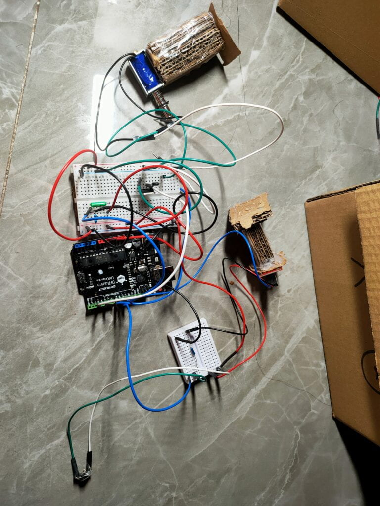
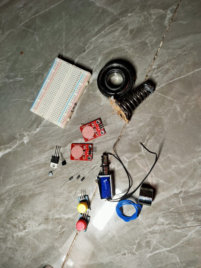
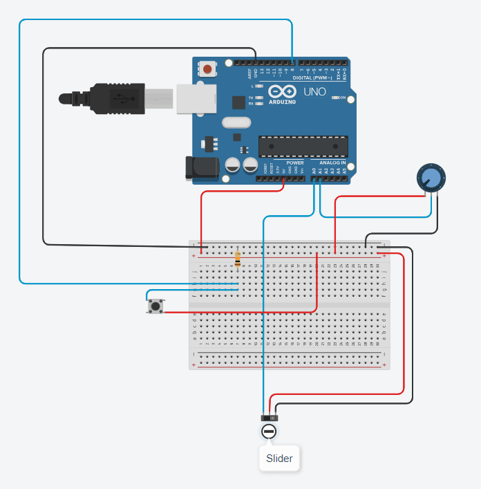
For the Arduino component, the project uses simple hardware:

      1. Button
        • Disarms the player using the keyboard and mouse
      2. Slider Potentiometer
        • Controls the speed of the game
      3. Rotating Potentiometer
        • Controls the size of the enemies

The following block is the Arduino code:

const int SLIDER = A0;
const int POTENTIO = A1;
const int BUTTON_DISARM = 8;

bool disarmed = false;

long disarmTimer = 0;

int previousSpeedValue = 0;
int previousDisarmValue = 0;
int previousSizeValue = 0;

void setup() {
    Serial.begin(9600);

    pinMode(SLIDER, INPUT);
    pinMode(POTENTIO, INPUT);
    pinMode(BUTTON_DISARM, INPUT);

    Serial.println("Setup done");
}

void loop() {
    int speedValue = constrain(map(analogRead(SLIDER), 0, 1023, 200, 100), 100, 200);
    int disarmValue = digitalRead(BUTTON_DISARM);
    int sizeValue = constrain(map(analogRead(POTENTIO), 0, 1023, 100, 200), 100, 200);
    
    if(speedValue - previousSpeedValue != 0) {
        Serial.print("S");
        Serial.print(",");
        Serial.print(String(speedValue));
        Serial.println();
    }

    if(sizeValue - previousSizeValue != 0) {
        Serial.print("SI");
        Serial.print(",");
        Serial.print(String(sizeValue));
        Serial.println();
    }

    if(!disarmed && previousDisarmValue == 0 && disarmValue == 1) {
        Serial.print("D"); 
        Serial.print(",");
        Serial.println();

        disarmed = true;
        disarmTimer = millis();
    }

    if(disarmed) {
        if(millis() - disarmTimer >= 5000) {
            disarmTimer = 0;
            disarmed = false;
        } 
    }

    previousDisarmValue = disarmValue;
    previousSpeedValue = speedValue;
    previousSizeValue = sizeValue;

    delay(10);
}

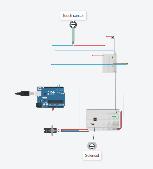
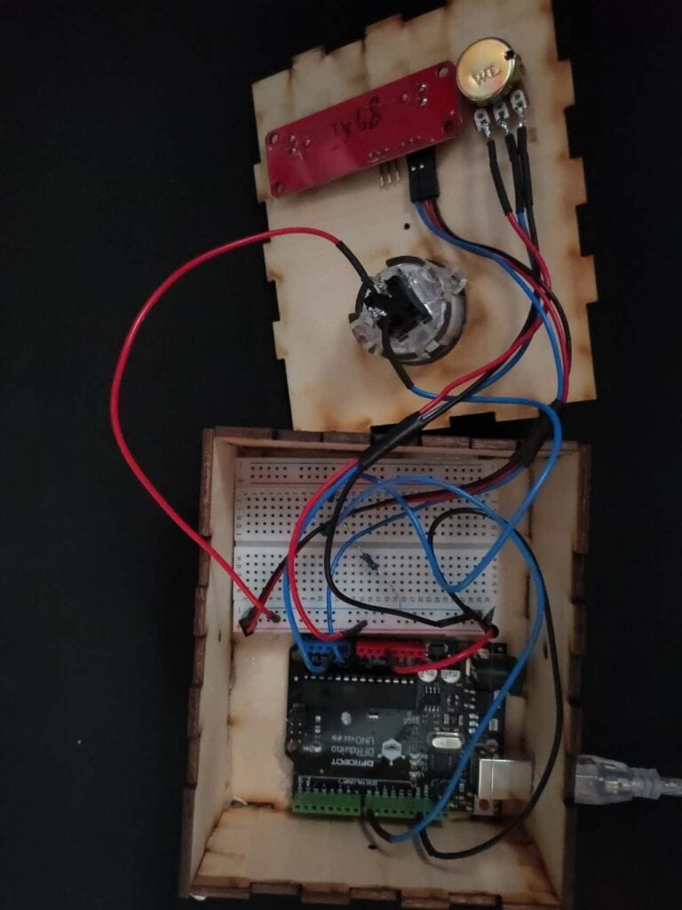
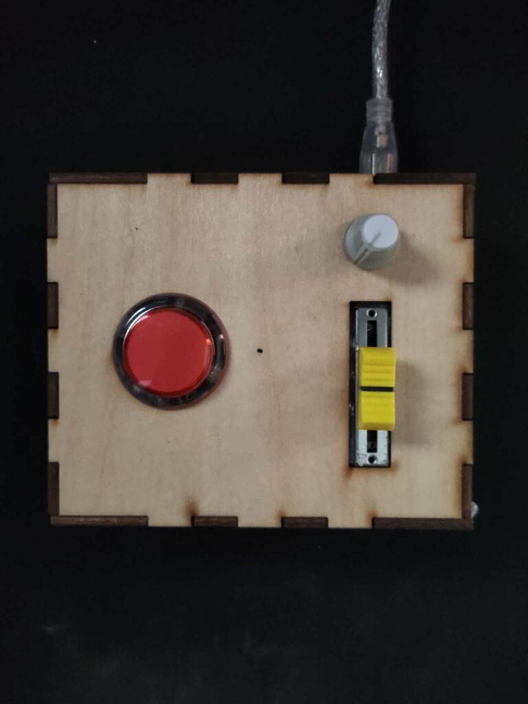
The important part of the Arduino code is where the signals are sent over to Processing only when it detects a change in the inputs instead of constantly sending values over. This makes sure that Processing does not slow down because it is overloaded with data. The Arduino code also has a timer system to prevent the button from being pressed many times in the span of, in this case, 5 seconds. The final circuit diagram and picture of the Arduino component is as follows:

Circuit diagram

Controller for the game (closed)

Controller for the game (closed)

Reflection

Majority of the project is the code in Processing, as such, making sure that the game works was my priority before moving into the Arduino component of the project. Since I was making a video game, it was difficult to find balance between gameplay and complexity – both regarding the mechanics of the game itself and how players are interacting with the video game. I felt like the controls for both players are very simple and there could be more improvements to what the players can or cannot do such as:

      1. The player with keyboard and mouse can do more things than shoot and move
      2. More details such as sound effects
      3. Replace keyboard and mouse into a different type of controller to give a more “arcade” feel

The most important thing that I learned from this project is that, in context of creating video games, everything about the game, both the digital and physical experience, must be thought of and well-balanced. 

Citations

Assets used in the project:

Weapon pack by VladPenn. https://vladpenn.itch.io/weapon

Character pack by Penusbmic. https://penusbmic.itch.io/sci-fi-character-pack-12

Disassembly

Midterm Documentation

Fixed?
Satya Tirtha
Rodolfo Cossovich

Fixed is inspired by a small puzzle that I remembered seeing in one of Chris Ramsay’s YouTube channel or his Instagram (@chrisramsay52) where he solves puzzles – both powered and not powered by electricity. Specifically, it was one puzzle where he had to spin a box to complete it. Back then I was amazed and later realized that a tilt sensor would give that same effect. Hence, I came up with the initial thought of making a puzzle that goes against “normal thinking” – like somehow forcing the user to spin instead of tilting to activate a tilt sensor.

Process of Making Fixed?

Since the project is about doing things that are not “normally thought of”, I decided that the mechanisms is more important than the physical design of the product. Because of this, the approach that I took when building the project is the opposite of what one would normally go for, which has its pros and cons that is written at the end of the blog. During the process of building, I would first develop the program before the physical product. This way, I could just later design and make something that could make use of the mechanism.

Initial Design

Initial Design of Fixed?
The initial sketch for Fixed?

The initial design for the project was simple – it was a cardboard box that had an electromagnet, a solenoid, push button, a tilt sensor and an Arduino. At this point, I knew that spending more time on the design will be less productive; hence,  I decided to write the code down before building anything concrete. 

To complete this puzzle, users were initially supposed to:

      1. Spin the box, activating the tilt sensor
      2. The solenoid will push a pin out
      3. The user must use the pin to press the button
      4. The user must wait for a few seconds
      5. Anything that the user do after a few seconds is over will unlock the box

However, this changed as I further developed the project.

Project Development

Since the project is supposed to be done in stages, it was developed and tested in a “modularized” way and the puzzle ended up having these features and sensors:

      1. The tilt stage
        • Tilt sensor
      2. Solenoid pushed out, where users will have to push it back in
        • Solenoid
        • Touch sensor (to detect whether the solenoid has been pushed back in)
      3. The waiting part of the puzzle
      4. The button push to finish puzzle
        • Push button
        • LED (to indicate that the puzzle has been completed)
        • Servo (to indicate that the puzzle has been completed)

Each of these stages were first coded then tested with the previous stages – for example, when stage 3 is tested along with stages 1 and 2 to ensure that everything works smoothly. In the end, I decided that the mechanisms will be put in a “robot” instead of a small puzzle box. The reason is that puzzles that Chris Ramsay have done have themes and I could not think of one that could be made wit ha small puzzle box; hence, I decided to have the theme of “fixing a broken robot” through “not normal” processes; however, at the end, users will only have to press a button to “fix” it. The series of images show how they were developed:

Development for stage 1
Developing tilt stage
Development for stage 2
Developing solenoid and touch stage
Development for stage 3
Developing push button stage

The code entirely follows the design pattern of states, which is hyperlinked for reference and will not be explained further in this blog post. The full code is put in the appendix. An example of a state:

class TouchStage : public Stage {
    private:
        int prevTouchState = 0;
        bool onTouchTimer = false;
        int timer = 0;
        bool completed = false;
        bool calibrated = false;

    public:
        TouchStage() {
            Serial.println("Touch stage");

            if(digitalRead(INPUT_TOUCH) == 0) {
                calibrated = true;
            }
        }

        bool checkComplete() {
            return completed;
        }

        Stage* nextStage() {
            return new ButtonStage();
        }

        void execute() {
            int touchInput = digitalRead(INPUT_TOUCH);

            if(calibrated && prevTouchState == 0 && touchInput == 1) {
                onTouchTimer = true;
                digitalWrite(OUTPUT_PUSH, LOW);
            }

            if(!calibrated && touchInput == 0) {
                calibrated = true;
            }

            if(onTouchTimer) {
                timer += DELAY;
            }
            
            if(timer >= 5000) {
                Serial.println("Moving arm up");

                armServo.write(60);

                onTouchTimer = false;
                
                completed = true;
            }
        }
};

In short, each stage will keep executing its designated action, check for its completion – it will check for the inputs from their designated sensors, and then go to the next stage if it is completed. This code will make the puzzle loop itself, which was developed for the User Testing phase so that I will not have to manually press the reset button on the Arduino repeatedly.

Changes After User Testing

A big change that I had made to the project was having some form of animation that tells the user that the puzzle has been completed AND is restarting. This leads to one of the bigger decisions that I have to make when I coded was deciding whether I should make the movements non-blocking (checking the timer) or blocking (using delay). The robot eye’s flickering animation uses delay afterwards as I do not want the users to do anything during the animation; however, as the robot is shutting down – when its arm starts slowing down – I used a non-blocking method of animation since I want the eye to flicker at the same time. This is as follows in the animation of the robot:

                ....

                for(int i = 0; i < 255; i += 10) {
                    if(random(1, 10) < 3) {
                        analogWrite(OUTPUT_LED_EYE, 0);
                        delay(50);
                    } 
                    analogWrite(OUTPUT_LED_EYE, eyeBrightness);
                    eyeBrightness = i;
                    delay(50);
                }

                alive = true;
            
                delay(1000);

                ....

            if(waveCount < 10) {
                if(timer % 150 == 0) {
                    if(armUp) {
                        armServo.write(80);
                    } else {
                        armServo.write(60);
                    }

                    waveCount += 1;
                    armUp = !armUp;
                }
            }

A major issue that the project had was during the second stage where users have to push the solenoid back into the robot’s head. The solenoid’s and touch sensor’s non-ideal placement made it such that the program thinks that the user has already pushed it back into the touch sensor – activating the timer move on to the next step in that stage. However, I modified the code to try to take account for that problem by checking if the touch sensors starts in an activated state. Furthermore, the solenoid would sometimes not activate properly – which could be because of bad wiring or just a lack of current passing through it. This is as follows in the second stage of the puzzle:

...

    private:
        int prevTouchState = 0;
        bool onTouchTimer = false;
        int timer = 0;
        bool completed = false;
        bool calibrated = false;

    public:
        TouchStage() {
            if(digitalRead(INPUT_TOUCH) == 0) {
                calibrated = true;
            }
        }

        ...

A minor change that I made was the battery placement. Initially, the batteries were placed in the head of the robot; however, I found out that it imbalanced the head, which made it tilt – constantly activating the tilt switch. To fix this, I moved the batteries into the body instead and slightly lifted the tilt switch so that it is always in a deactivated position.

Connection between head and body
How the head and body are connected

The final circuit diagram is as follows:

Circuit diagram
Final circuit diagram

Reflection

Before the final presentation, my project broke down – which I still could not completely determine why. I had planned to take a video during this stage to showcase the interaction between a user and the product (since that my project also broke during user testing); however, since it broke, I could not take one. From this, I learned that documenting more regularly during the development phase could have prevented this problem; moreover, I could have recorded an example interaction between myself and my project.

I have also learned other things on the development process, which is summarized as follows:

      1. “Reversed engineering” development process
        • (Pro) Physical design can be more flexible since mechanism is finished first
        • (Con) Physical design should be given more thought before developing mechanisms
        • (Con) Might be usable in small-scale projects; however, should not be done in larger-scale projects
      2. The “modularized” method of development
        • (Pro) Easy debugging since we make sure previous parts are working
        • (Pro) Makes sure that the mechanisms are working properly before fitting into physical product

Appendix

Full code

#include <Servo.h>

// pin numbers are constants
// as they should not change
const int INPUT_TOUCH = 10;
const int INPUT_TILT = 9;
const int INPUT_COMPLETE = 8;

const int OUTPUT_PUSH = 3;
const int OUTPUT_SERVO = 5;
const int OUTPUT_LED_EYE = 11;

const int DELAY = 10;

Servo armServo;

class Stage
{
    public:
        virtual bool checkComplete() { 
            return false; 
        }
        virtual Stage* nextStage() {
            return NULL;
        }
        virtual void execute() {
        }
};

class TiltStage : public Stage
{
    public:
        TiltStage();
        bool checkComplete();
        Stage* nextStage();
};

class ButtonStage : public Stage {
    private:
        int prevButtonState = 0;
        bool armUp = true;
        bool completed = false;
        int timer = 0;
        bool alive = false;
        int waveCount = 0;
        bool animating = false;
        int eyeBrightness = 0;

        bool onReleased() {
            int input = digitalRead(INPUT_COMPLETE);

            if(prevButtonState == 1 && input == 0) {
                prevButtonState = input;

                return true;
            }

            prevButtonState = input;
            
            return false;
        }

    public:
        bool checkComplete() {
            return completed;
        }

        Stage* nextStage() {
            armServo.write(180);

            return new TiltStage();
        }

        void animate() {
            // here it is okay to use delay
            // since we don't want the user
            // to be interacting during
            // the 'animation'

            if(timer == 0 && !alive) {
                for(int i = 0; i < 255; i += 10) {
                    if(random(1, 10) < 3) {
                        analogWrite(OUTPUT_LED_EYE, 0);
                        delay(50);
                    } 
                    analogWrite(OUTPUT_LED_EYE, eyeBrightness);
                    eyeBrightness = i;
                    delay(50);
                }

                alive = true;
            
                delay(1000);
            }
            
            if(waveCount < 10) {
                if(timer % 150 == 0) {
                    if(armUp) {
                        armServo.write(80);
                    } else {
                        armServo.write(60);
                    }

                    waveCount += 1;
                    armUp = !armUp;
                }
            } else {
                if(waveCount < 20 && timer % (150 + (waveCount - 10) * 50) == 0) {
                    if(armUp) {
                        armServo.write(random(60, 80));
                    } else {
                        armServo.write(random(80, 100));
                    }

                    waveCount += 1;
                    armUp = !armUp;
                    timer = 0;
                } else if(waveCount >= 20) {

                    if(timer % 20 == 0)
                        eyeBrightness = constrain(eyeBrightness - 20, 0, 255);

                    armServo.write(180);
                    analogWrite(OUTPUT_LED_EYE, eyeBrightness);

                    if(eyeBrightness <= 0)
                        completed = true;
                }

                if(timer % 20 == 0) {
                    if(random(1, 10) < 3) 
                        analogWrite(OUTPUT_LED_EYE, 0);
                    else
                        analogWrite(OUTPUT_LED_EYE, eyeBrightness);
                }
            }

            timer += DELAY;
        }

        void execute() {
            if(onReleased()) {
                animating = true;
            }

            if(animating) {
                animate();
            }
        }
};

class TouchStage : public Stage {
    private:
        int prevTouchState = 0;
        bool onTouchTimer = false;
        int timer = 0;
        bool completed = false;
        bool calibrated = false;

    public:
        TouchStage() {
            if(digitalRead(INPUT_TOUCH) == 0) {
                calibrated = true;
            }
        }

        bool checkComplete() {
            return completed;
        }

        Stage* nextStage() {
            return new ButtonStage();
        }

        void execute() {
            int touchInput = digitalRead(INPUT_TOUCH);

            if(calibrated && prevTouchState == 0 && touchInput == 1) {
                onTouchTimer = true;
                digitalWrite(OUTPUT_PUSH, LOW);
            }

            if(!calibrated && touchInput == 0) {
                calibrated = true;
            }

            if(onTouchTimer) {
                timer += DELAY;
            }
            
            if(timer >= 5000) {
                Serial.println("Moving arm up");

                armServo.write(60);

                onTouchTimer = false;
                
                completed = true;
            }
        }
};

TiltStage::TiltStage() {
    digitalWrite(OUTPUT_PUSH, LOW);
}


bool TiltStage::checkComplete() {
    return digitalRead(INPUT_TILT);
}

Stage* TiltStage::nextStage() {
    digitalWrite(OUTPUT_PUSH, HIGH);

    return new TouchStage();
}

Stage* currentStage;

void setup() 
{   
    Serial.begin(9600);

    currentStage = new TiltStage();
    armServo.attach(OUTPUT_SERVO);

    pinMode(INPUT_TILT, INPUT);
    pinMode(INPUT_COMPLETE, INPUT);
    pinMode(INPUT_TOUCH, INPUT);

    pinMode(OUTPUT_PUSH, OUTPUT);
    pinMode(OUTPUT_SERVO, OUTPUT);
    pinMode(OUTPUT_LED_EYE, OUTPUT);

    armServo.write(180);
    digitalWrite(OUTPUT_PUSH, LOW);
}

void loop()
{
    currentStage->execute();

    if(currentStage->checkComplete()) {
        Stage* newStage = currentStage->nextStage();
        delete currentStage;
        currentStage = newStage;
    }
    
    delay(DELAY);
}

Disassembly

Non-Arduino kit materials
Materials that are not part of the Arduino basic kit disassembly