Task 1: Build the Circuits
Step 1

The circuit makes a buzzing sound when the push button is pressed, and it stops buzzing when the button is unpressed. The button acted as a switch: when the button is pressed, the switch is on, and when the button is unpressed, the switch is off. Each time we press the button, the electrical current is able to flow from the battery(source) to the wire, and pass through the buzzer, allowing it to buzz.
To built the circuit of this step, my partner Ruiqi and I first inserted the wire of the battery into the power and ground bus on the bread board. Secondly, we plugged in the buzzer and the button. We make the path for the current to flow through the circuit as we placed the wire between the positive hole and the buzzer, buzzer and the button, and the button and the negative hole to form a complete circuit.
We pressed the button for the first time and nothing happened, the buzzer doesn’t make any sound. So, we sought an assistant to define the problem we made. It turns out that the holes on the breadboard that we placed the pins of the buzzer is not connected. By looking at the back side of the breadboard, we noticed that the holes are connected horizontally in lines, but not vertically. The circuit finally worked, and buzzer made sounds when pressed after we plugged it in the holes that are actually connected by the wires underneath.
Step 2
In step 2, additional branch consisting of a resistor(R2) and a LED(LED2) was placed in the existing circuit. We plugged in wires to the breadboard to create paths between the source and the resistor, and the LED2 and the button. When the button is pressed the current flow to the buzzer, and the resistor and LED2. My partner and I succeeded to built this circuit with one trial. The buzzer buzzed and the LED2 turned on at the same time when we click the button. In other words, the circuit transmit the morse code through the flash of LED and the buzz that the buzzer creates at the same time when the button is pressed in a pattern.
Step 3

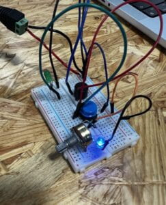
We added another branch consisted of a resistor(R1), a potentiometer, and a LED (LED1) to the circuit, and created a path using wires that connect the components with the existing path in step 2 that has current flow so that the electrical current from the battery could also flow through them. The LED1 was supposed to be lighted up, however, it didn’t. It took a while for me and my partner to figure out the problem. It turned out that we placed both anode and cathode pins of the LED1 in the same connected group of hole where one of the three pins of potentiometer connected with resistor is also placed. This made the current to flow to the path underneath the LED1 through the wire within the breadboard instead of LED1 because the resistance level of LED1 is much higher than the wire underneath. By plugging in the anode pin of LED1 into the hole in the same hole group of POT, and the cathode side of LED1 into a hole in the next line of hole group, the LED1 successfully lighted up.
One evident difference between the circuits of step 2 and 3 is that the circuit in step 3 has an extra LED that lights up constantly as long as the battery of the circuit continuously provide the electricity current.
Task 2: Build a switch


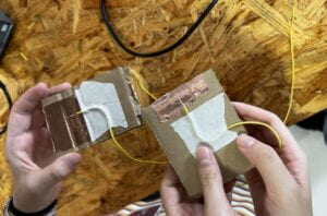
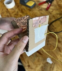
To make the switch, first, we taped the copper tape on the cupboards. Then, we fixed the wires on the cupboards by curling them into an angle, and sticking a paper tape above it.
It was the first time for my partner and me to use the soldering iron to melt down the metal alloy, so we handled the tool gingerly to avoid burning fingers in the lab. For that reason, we position the angle of the tip too vertically that it took a while for the metal to melt down and stick the wire on the copper tape. With the help of professor Rudi and his advise, we position the soldering iron to be horizontally pressing the wire and the metal alloy. We successfully sticked the wire on the cupboard with more melted metal alloy as positioning the soldering iron horizontally increased the heating area and its efficiency to melt the metal alloy.
Task 3: Switch the switches and send a message

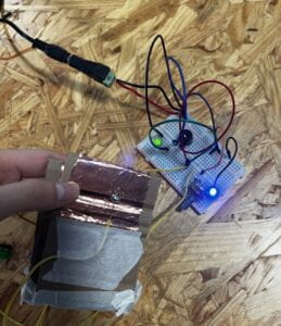
Once we reached task 3, we replace the push button with the DIY cupboard switch we made in task 2. I clap the tips of the DIY switch together to test whether the DIY switch and the buzzer of this circuit work. While testing the circuit, the buzzer made the sound “beeeep, beeeep, beeeep,” which represents the letter “O.”
Now that we have made our simple telegraph sounder, my partner and I decided to send a secret word, help, to another team and see if they will recognize the word and provide us any help. So we clap the switch in the pattern for the buzzer to sound, “beep beep beep beep…beep…beep beeeep beep beep, beep beeeep beeeep beep.” Sadly, the neighbor team didn’t recognize our secret word nor did they give us any help.
My Answers to Additional Questions
Question 1: What is the function of the resistor R1?
While we intended to use LED, it is important to avoid the amount of current to exceed the range of LED’s range of forward current ratings. Not limiting the flow of current may result to a damaging or a bursting of the LED, therefore, a resistor is needed. When the current flow form the battery to R1, R1 limit the flow of the current that passes LED1. The resistor R1 is placed within the parallel circuit to protect LED1 from damaging.
Question 2: Looking at the following circuit, draw its diagram by yourself.
Question 3: After reading The Art of Interactive Design, in what way do you think that the circuit you built today includes interactivity? Which degree of interactivity does it possess? Please explain your answer.
After reading The Art of Interactive Design, I learnt that interaction take place between the communication of two actors through the repeatable cyclic steps of listen, think, and speak. Additionally, there is a way of interpreting the level of interactivity through the quality of each three steps, and the depth of the engagement of both actors.
The circuit that my partner and I built included interactivity by being one of the two actors that communicate during the interaction, in which the person that press the DIY switch is the actor that interacted with the circuit. In the first step of the interaction, I press the switch, and the circuit “listened” to my message as the button on it is pressed. Secondly it went trough its “thinking” process as the current flow to the buzzer. Finally in the third step, the circuit “spoke” with the response of the buzzer buzzing in the pattern of morse code that I pressed.
I think that this circuit has a low interactivity just like the refrigerator example that is mentioned in the reading. The circuit only simply response with the buzzing sound and a light turning on when the button is pressed. Both actors (the circuit and the person that pressed the button) only performed a very simple interaction with little engagement.
Question 4: How can Interaction Design and Physical Computing be used to create Interactive Art?
Both interaction design and physical computing involve in the content of interaction in a similar way like interaction art. In physical computing, the interactive systems can receive the messages from their environment using their sensors and they give the responses after they process what they received. Interaction design can be inputted into physical computing to create an interactive art through creating a program that allows the audience or the actor to artistically and physically interact with systems from the physical computing to achieve a certain purpose. For example, Zack Lieberman’s project, Drawn, allowed a person to draw on the installation and interact with the art they created as they swiped and touched on the screen that made the parts of their art pieces to swim in directions. Subsequently, this interactive art entertained the users that physically and emotionally experienced it.