Task 1:
Step1:
- The series circuit lets the current flow through only one path in a closed loop. The button controls the state of the loop(closed/open). The buzzer makes voice to indicate the circuit works in a correct way.The power provides electrical energy and a load.
- The circuit worked. We didn’t encounter any problems. After figuring out how the breadboard functioned, my partner and I connected components together with wires. Eventually, we hit the button and the buzzer went off smoothly.
Step2:
- The parallel connection circuit lets the current flow through two paths in closed loops. The button controls the state of the loop(closed/open). The LEDflashes to indicate the circuit works in a correct manner. The resistor resists the flow of electricity and controls the flow of current. The buzzer makes voice to indicate the circuit works in a correct way.The power provides electrical energy and a load.
- The circuit worked at last. BUT we did encounter something problematic. The LED didn’t flash at first, so we checked the circuit and found out the resistance was wrongly connected and we forgot another wire which was necessary for the circuit. Then after we made some adjustments, the LED and buzzer both worked.
Step3:
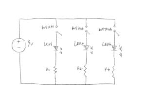
- The parallel connection circuit lets the current flow through three paths in closed loops. The button controls the state of the loop(closed/open). The LED flashes to indicate the circuit works in a correct manner. The resistor resists the flow of electricity and controls the flow of current. The POTserves as a resistor with a sliding contact which outputs an adjustable voltage. The buzzer makes noice to indicate the circuit works in a correct way. The power provides electrical energy and a load.
- The circuit worked at last. My partner and I added another circuit and a few more components. However, one problem still existed during the process. The POT failed to provide an adjustable voltage because it wasn’t connected properly with the LED. After we made corresponding modification, the circuit functioned perfectly.
Task 2:
- My partner and I first stuck two cardboards together, and then stuck two long wires with copper tape on them. After that, we use soldering techniques to fix the wire firmly on the cardboards.
- I’ve learnt how to solder wires in order to fix them on the cardboards (in fact it’s the first time I’ve ever soldered.). Besides, I verified the electrical conductivity of copper by practice.
Task 3:
- To begin with, My partner and I replaced the push button used in task 1 with the newly soldered DIY paddle. Then we used the morse code to convey different information. I found it intriguing to combine soldering, electronics and information conduction together, which might be a vivid example of what “interaction” actually means.
Additional questions:
- Question 1: Because LEDs need resistors to help limit the current that passes through them so they do not get damaged. Every LED has a current rating that should not be exceeded and resistors have the ability to limit the current to below the maximum allowable current allowed for the LED.
- Question2:

- Question3: I believe the circuit includes interactivity in the following three aspects.
Input: When you turn on/off the switch.
Process: the current flows through the circuit in a closed loop.
Output: the buzzer correspondingly makes the sound.
- Question4: By creating projects about live and on-stage painting, about “car driving”, and about tools for eyewriting.