Dear Professor Gottfried:
Here’s my work for recitation one, I finish it with my partner Celeste Hu, whose net ID is hh2856. So our videos are the same.
Recitation 1: Electronics and soldering.
Task2
Step 1: Build the switch
Content: I sticked the copper tape to the card board, then soldered the wire with the board.
Reflections: Everything went quite well.
The recording of our works can be seen in the recording of circuit3
Task1
Step 2: Connect the first circuit
Content: The circuit was used to ring the buzzer, when someone pressed the button, the buzzer would beep.
Reflection: We didn’t know the breadboard quite well, so the first three connecting attempts failed, basically its because we put the electronic elements in different lines without using cables(or use the wrong cable) to connect them. I believe after this recitation, we can master the basic skills of using breadboards.
Circuit 1
Step 3: Connect the second circuit
Content: the newly added LED was used to show whether the buzzer was activated. When the button was pressed, the LED should be lit up while the buzzer beeps. The resistor is used to protect the circuit, since the value of the resistance of the LED is too small, which may cause short circuit.
Reflection: Actually the first LED we used was broken, but we believe the problem was with the circuit, which was really a waste of time, so next time we should be more confident with ourselves and try to consider problems in a different way.
Circuit 2:
Step 4 Connect the third circuit.
Content: I thought the additional circuit was used show whether the power is activated, and can be used to check where the problem is if the buzzer or LED2 didn’t work. If LED1 is lit up, then there may be problem with the circuit in the former steps, however, if it didn’t light up, then maybe the problems with the main circuit or the power. But if it’s for this usage, then there’s no need to use a pot, since a switch can also do the work of deciding whether to light up the light. So I’m a bit confused.
Reflection: The circuit before was too complicated since we didn’t manage it well, resulting in using too many cables and inappropriate positioning of elements, which then resulted in difficulties in inserting the materials for Step 4.
Circuit 3
Answers to questions
Question1: The resistor R1 is used to protect LED1. Since the resistance value of the potentiometer can be quite small, without resistor R1 the current might be too strong, which will cause damage to LED1. So R1 was there to protect LED1 form burnt.
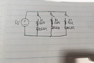
Question2:
The answer is as follows (I’m not sure about the value of the resistance) (The power is 9v instead of 6v, sorry for putting down the wrong number)

Question3:
First, the process we assemble the circuit involves interaction: We put electronic elements on the breadboard, then these things reply us with the consequence of whether the buzzer beeps or the LED lights, according to our ways of connecting, then we reply the consequences by either correct the circuit or move to the next step. In the whole process, we listen, speak(correct the circuit) and think, the breadboard also listen(being assembled and inserted with different elements) speak(conveying whether the circuit worked) and think(let the current flow to check whether it works). The breadboard has low interactivity, because it can’t completely the process on its own.
Second, our communicating with the professors or the teaching assistants involves interaction. Both of the two sides listen, speak and think. It has high interactivity.
Question4:
People can do this by finding the factors of a certain form of art, and find other similar factors from other actions to create interactive art. For example, since drawing involve moving of ‘pens’ to create images, so Mr.Lieberman found other actions involving movements like driving or eyesight moving, which then becomes the projects ‘ip font’ and ‘Eye Writer’.