Task 1
For task one, we built a basic circuit. It is a simple circuit, with power, switch, and buzzer connecting with each other one by one. Switch controls the on and off of the electricity. Power provides electricity. The Buzzer would make sounds when the electricity is on. At first,
we encountered some difficulties because we did not know the organism of the breadboard. We also misunderstood the inner structure of the switch. After consulting our professors and assistants, we figured out the right way to connect the components.
Working with my partners was awsome. We made up for each other’s knowledge gap, pointing out the mistakes we repectively made. I felt great about our collaboration.
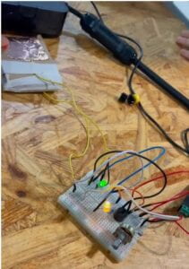
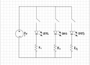
Then, we started to upgrade our circuit. We have added another branch to the original circuit. There is a resistor with a fixed resistance on this branch, and an LED light that emits light. This branch is separated from the main road behind the switch and connected to the Buzzer in parallel, so that when the buzzer sounds, the LED light also flashes. The function of the fixed resistor here is to protect the LED lamp and prevent the LED from burning out due to excessive current. We also encountered some problems because one of the wires was not connected to the right row, because of which the LED light did not glow at the beginning, only the buzzer making the sound. Luckily, we figured it out later and we put the wire in the right way.
It is important to note that the positive and negative terminals of an LED light need to be distinguished by the length of the wire on either side — the long side is the positive terminal and the short side is the negative terminal. Connect the positive terminal first, then the negative terminal
The discussion between me and my partner was extremely significant for us to debug the circuit when the LED light did not glow.
In step three, we made the circuit even more complicated. We added another branch to the circuit. We added a third branch to the second circuit. On the third branch, there is a fixed resistance resistor, a variable resistance, and an LED light. This branch is separated from the main road before the switch and is parallel with the two previous branches. That way, the LED light on the third branch will always be on, whether the switch is on or off. When the switch is closedm, the two LED lights will light up at the same time, and the Buzzer also starts to make sounds.
Based on what we have learned and practiced in step 1 and 2, we successfully made step 3 in a short time.
Task 2
For task 2, we first went to the next lab, and Professor Rudi taught us how to make a switch. First, we use pliers to remove 1-3 cm of the rubber protectors from each end of the wire. Then, we attach the copper tape to the front of the cardboard. A section of the wire is welded to the copper tape so that the current can flow smoothly to the copper tape. Glue two pieces of cardboard together. When the front ends of the cardboard touch together, the copper tape on the cardboard touches each other, creating a closed loop through which electricity passes, which makes it an artificial switch. The circuit can be opened and closed by simply pressing the cardboard.
Task 3
For task 3, we took the switch off the breadboard first, and then made a note of the number of lines connecting the switch, and connected the wires at both ends of the manual switch to the position where the switch was originally located. In this way, the original switch is replaced by a manual switch. We can control the opening and closing of the first and second branches just by pressing the front end of the cardboard. When we press the cardboard, the LED light and Buzzer will operate simultaneously, and when we release the cardboard, the LED light and Buzzer will turn off simultaneously. In this way, under the control of my companion, we managed to send out SOS Morse code from this circuit by controlling the timing of the board press
Question 1: The resistor R1 is connected in series with the LED lamp. This limits the amount of current in the circuit and prevents the LED lamp from burning out due to excessive power.
Question 2

:
Question 3: According to The Art of Interactive Design, “interactive”, is a cyclic process in which two actors alternately listen, think, and speak(3). I think our circuit in this recitation shows its interactivity. I first think of my task–making “SOS” in morse code, which then drives me to press the cardboard. This is my process of “thinking” and “speaking”. Then, the basic structure we designed for the circuit makes it a basic logic circuit, through which the circuit gets to process the signal we give it–which is the pressing of the cardboard. This, to a certain extent, shows its “listening” and “thinking” process. Then it shows its “speaking” process by blinking and buzzing. There is a complete process of interactivity through the working of this circuit. The degree of interactivity is not high, but we can not doubt its existence.
Question 4: In my opinion, interaction design can provide creative and framework support for design works. Through interaction design, works can be endowed with the ability to interact with the outside world and users. Physical computing provides technical support for the design works. Only through physical calculation can the works realize the technical interaction and transmission of information. The former is like the creator’s idea, and the latter is like the creator’s tool. Without either, high-level interactive art cannot be created.