Circuit Building process
- circuit1:fade
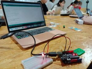
We build the circuit according to the diagram. We start the circuit from D9 on the Arduino Uno, connecting a resistor and a LED, and finally connecting the whole circuit with the ground. Then, we copied the code and uploaded it successfully. Everything went well when we were at this step.

- Circuit 2: toneMelody
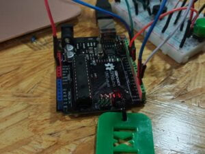
This circuit was quite similar to the first one. The LED was replaced by a buzzer and the resistor was removed. However, since we weren’t sure if we would use the former one, my partner and I built the second one without removing the first one. So the picture may look a little complicated but actually it is not.
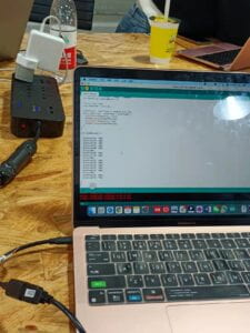
Then, we opened another code on the computer and uploaded it. Nothing went wrong as well.
- Circuit 3: Speed Game
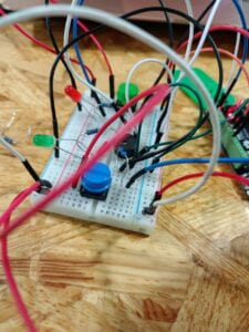
This one became much more complicated and my partner and I did spend some time building it.
we signed up the Tinkercad account and opened the example and the example diagram and code, just as the instructions said.
When building the circuit, we tried to reduce the whole circuit to some simpler ones, so every time we started connecting the cable from the holes on the Arduino, making the electricity passing the component on the breadboard and going back to the negative electrode on the breadboard.
However, though we had been really careful, we also made ignored some extremely important things. After finishing the works on the breadboard, we were so excited that we uploaded the code immediately, but only to find that the code could not be uploaded. After checking, we found we forgot to connect the negative electrode with the ground. So it even could not be a complete circuit. I think this is a simple but important lesson. Never should we forget to build out circuit a complete one.


After fixing it, we uploaded the code again. It succeed this time, but when we were about to play the game, there was only one button working. So we had to check the circuit again, and we found one of the buttons and the corresponding resistor were not in a line.

We reconnected them and uploaded the code one more time. Finally, it worked well and we could play with it!!!
Also, professor Andy helped us check our circuit once more. Thank him for his kindness and patience!!!
Questions
- Question 1: Propose another kind of creative button you could use in Circuit 3 to make the game more interactive. Read and use some material from the Introduction Chapter (pages xvii to xxix) of Physical Computing to explain why this button would make this game more interactive.
I want to change the form of simply pressing the button to a more complicated, interesting action. Maybe there can be a mini basketball shooting machine, the player should put the ball into the baskets and get the score. The player that first get the assigned sore wins.
The writer of this book breaks the process of physical computing down into 3 stages: input, output, and processing. When talking about input, he writes, “they are already happy with their ability to express themselves on a computer, either through the screen or through the speakers, but feel constrained by the input of a mouse and keyboard”. By changing the press button to a basketball shooting, the input becomes more complicated and challenging, people will take more work than just using their finger to press the button. Thus in my point of view, the game becomes more interactive.
- Question 2: Why did we use a 10K resistor with each push button? (Read the short explanation about pull-down resistors here)
“We can add in what’s called a pull-down resistor before the GND connection, which prevents short circuits when the switch is closed while still biasing the pin to 0V when the switch is open.” According to the explanation, the button is connected directly with the power supply and the GND, so a resistor is necessary to avoid a short circuit. As for why the value should be 10K, it is the recommended value, moreover, this proper value can allow much current passing at the same time ensure the short circuit would not happen.
The diagram for circuit3
