My Interaction Lab Recitation 10

GOAL

The goal of my recitation was to make a video that would change its speed depending on where potentiometer’s value is. Therefore, it would speed up the video if the value was less than 512 it would play the video faster and if less than that it would slow down or even stop the video. 
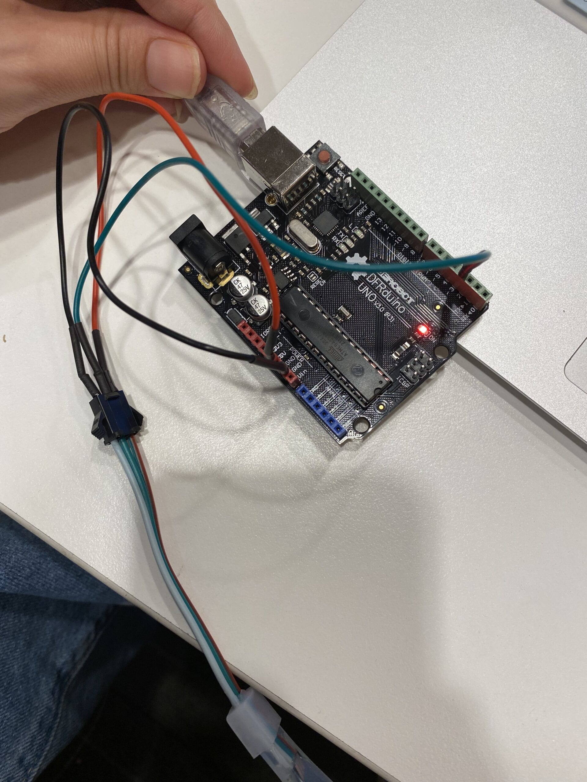
Arduino

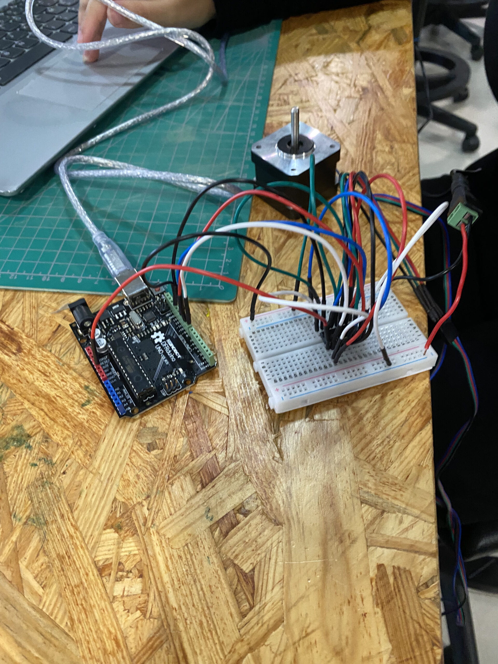
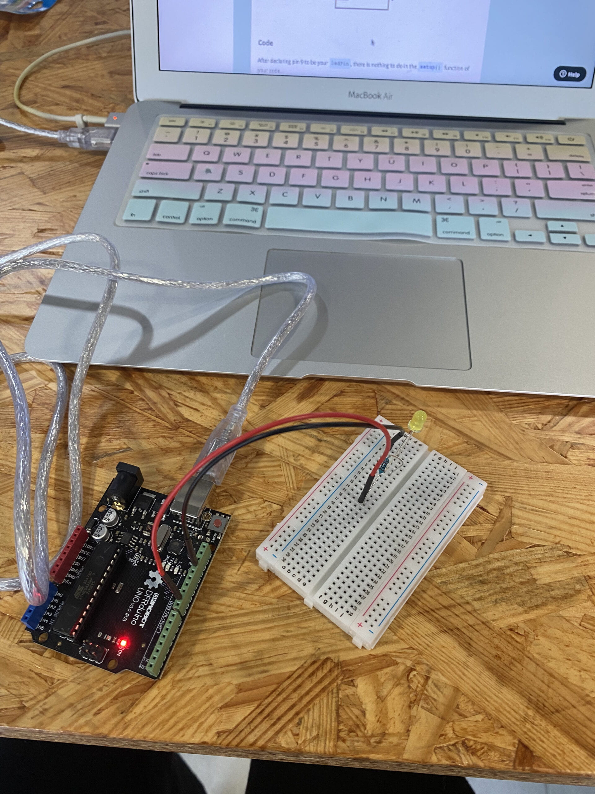
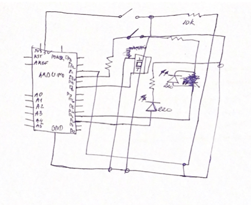
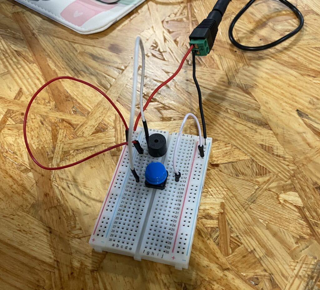
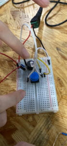
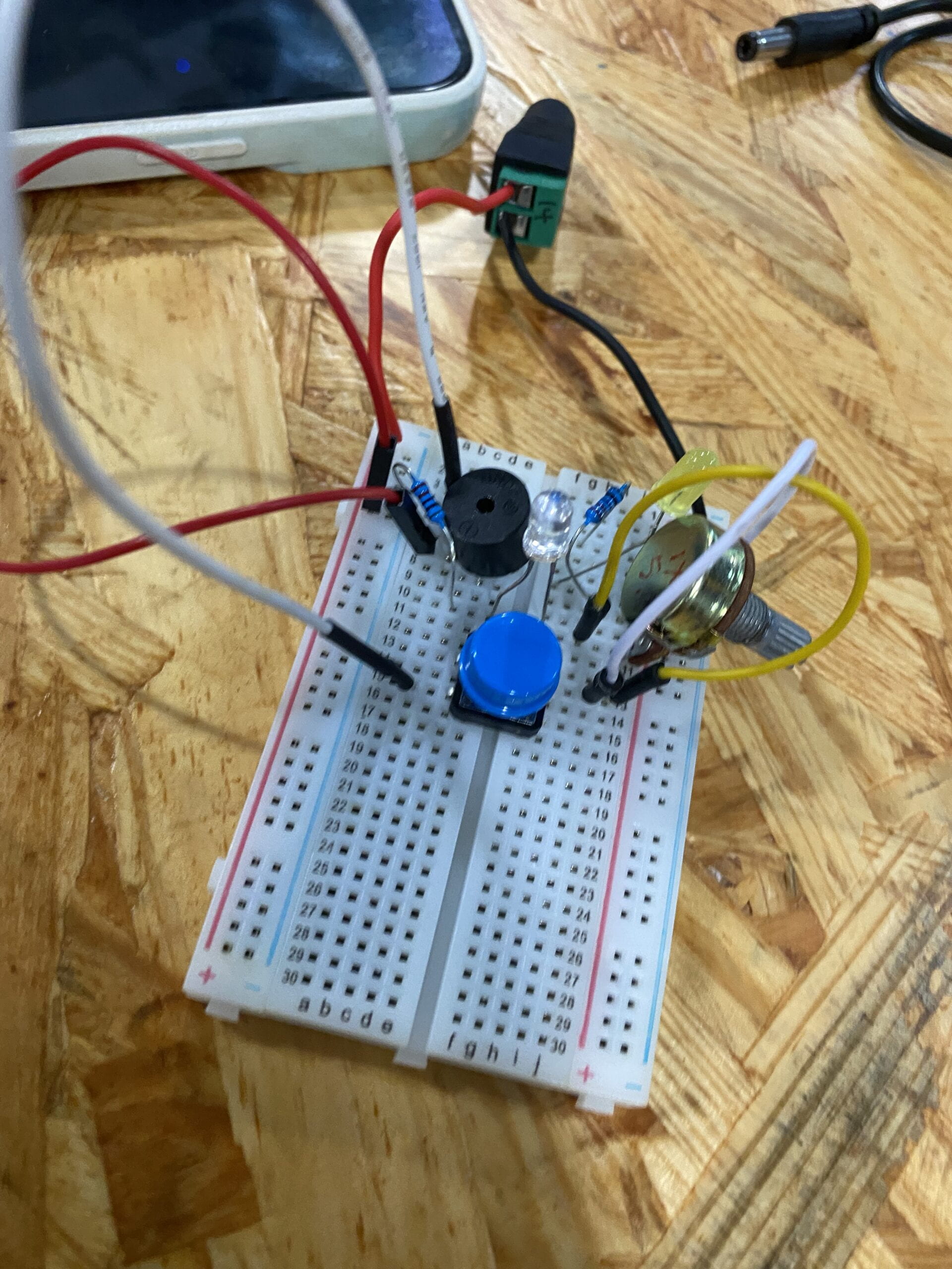
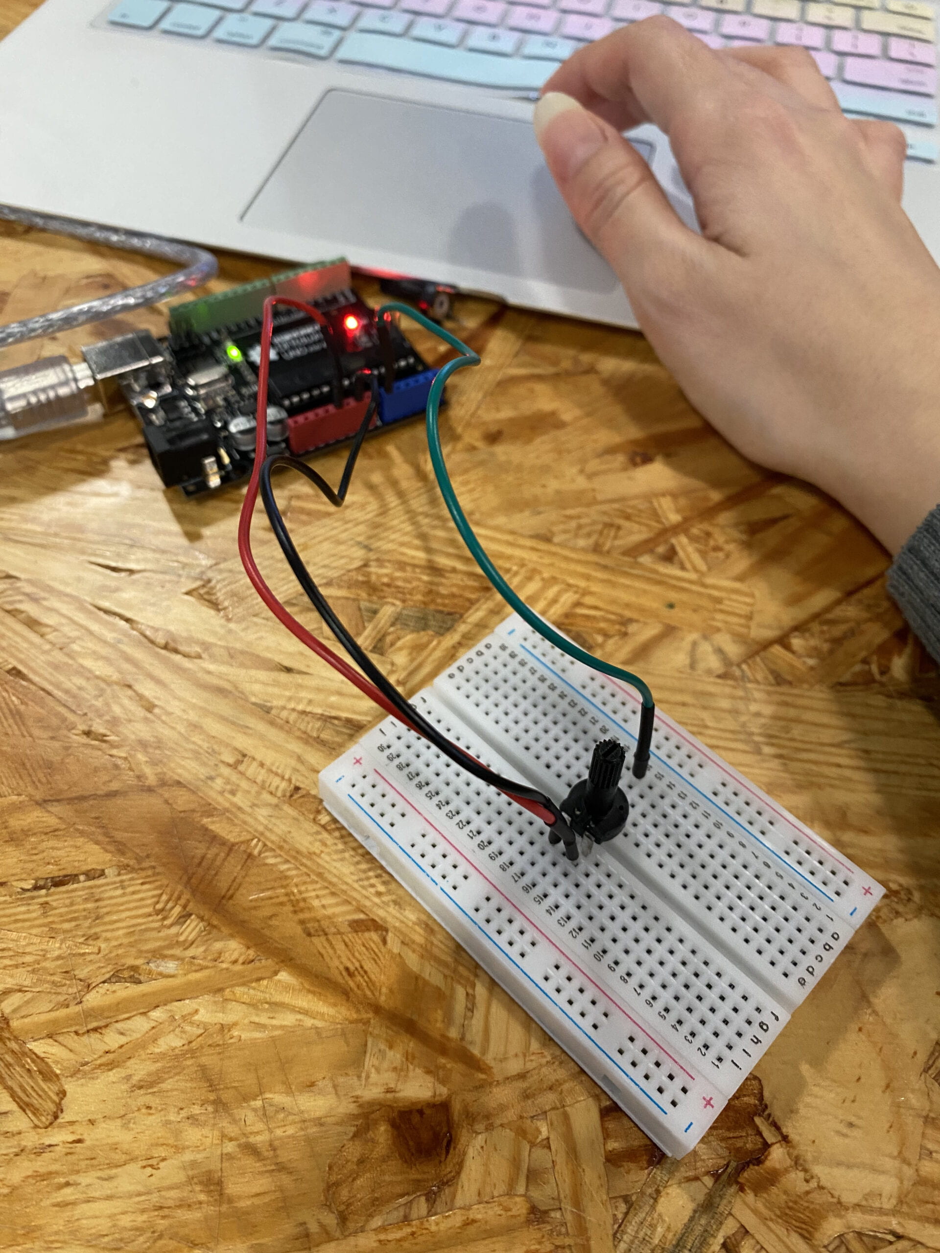
  • This was the most straightforward part where I had to attach the jump wires to the circuit with potentiometer.
  • Here is the code:
  • #include "SerialRecord.h"
    
    SerialRecord writer(1);
    
    void setup() {
      Serial.begin(9600); 
      pinMode(A0, INPUT);
    }
    
    
    void loop() {
        int sensorValue1 = analogRead(A0);
      writer[0] = sensorValue1;
      writer.write();
      // This delay slows down the loop. This can make it easier to debug the
      // program.
      delay(10);
      //print(sensorValue1);
    
    }
    

Processing

  • This was the hardest part of the recitation to create some conditionals so that the video will react to potentiometer bending left or right by increasing or decreasing the speed of the video. 
  • Here is the code:
  • import processing.video.*;
    
    Movie film;
    
    import processing.serial.*;
    import osteele.processing.SerialRecord.*;
    
    Serial serialPort;
    SerialRecord serialRecord;
    
    void setup() {
      size(800,700);
     film =  new Movie(this, "istock-802013730_preview.mp4");
      film.loop();
      String serialPortName = SerialUtils.findArduinoPort();
      serialPort = new Serial(this, serialPortName, 9600);
      serialRecord = new SerialRecord(this, serialPort, 1);
      colorMode(RGB,360,100,0);
    }
    
    void draw() {
    
      serialRecord.read();
      int filmS = serialRecord.values[0];
    
    
      if (film.available()) {
        film.read();
      }
      image(film, 0, 0);
      if(filmS < 512){ film.speed(4.0); } if(filmS >512){
    film.speed(0.5);
    }
    
    println();
      
    }

    Here is the final work: 

My Interaction Lab Recitation 7


Task 1. 

This was the most straightforward and easiest task in my opinion because we only had limited work with Arduino. We connected the LED to three different Arduino holes including ground, 5V, and pin 3 following the colors shown in the image. I’ve also successfully passed the LED test by making one light blink by going to the link examples of the Arduino FAST LED category. 

Task 2. 

I’ve also finished the second task relatively fast because we were given ready codes we needed to copy-paste, and it worked. The installation of the libraries has also been easy since we have seen how to do that before. 

Task 3. 

This was the most challenging step so far because there were too many questions on how to combine the work of an Arduino with Processing without using the same port at the same time. The step of copy-pasting one Processing code into the second one wasn’t as hard as step three where we had to add different lights to the LED. 

Task 4. 

This step made the previous one seem like child’s play. And I think without a proper image or a goal of what you want would make the task ten times harder. However, at the end of the day, I went for the same old ellipse which turned out to be a bunch of coins dancing to the beat of Harry Potter’s main theme song.

Code: 

Processing.

import processing.serial.*;
import osteele.processing.SerialRecord.*;
import processing.sound.*;

Serial serialPort;
SerialRecord serialRecord;

int W;         //width of the tiles
int NUM = 60;  //amount of pixels
int[] r = new int[NUM]; //red of each tile
int[] g = new int[NUM]; //red of each tile
int[] b = new int[NUM];


SoundFile sample;
Amplitude analysis;

void setup() {
    fullScreen();
  size(640, 480);
  W = width/NUM;

  String serialPortName = SerialUtils.findArduinoPort();
  serialPort = new Serial(this, serialPortName, 9600);
  serialRecord = new SerialRecord(this, serialPort, 4);
  serialRecord.logToCanvas(false);
  ellipseMode(CENTER);
  sample = new SoundFile(this, "Harry Potter Theme Song.mp3");
  sample.loop();
  analysis = new Amplitude(this);
  analysis.input(sample);
}

void draw() {
 background(200);
  float volume = analysis.analyze();
  int a = floor(map(volume,0,width,0,height));
  float diameter = map(volume, 0, 1, 0, width);
 for (int i=0; i<60; i ++) {
    fill(r[a], g[a], b[a]);
    ellipse(i*W+W*2, height/2, diameter/2,20) ;
  }
    r[a] = floor(random(100,255));
    g[a] = floor(random(200));
    b[a] = floor(random(90));

    serialRecord.values[0] = a; 
    serialRecord.values[1] = r[a];  
    serialRecord.values[2] = g[a]; 
    serialRecord.values[3] = b[a];  
    serialRecord.send();            
 
}
   

Arduino

 
#include "SerialRecord.h"
#include 

#define NUM_LEDS 60  // How many leds in your strip?
#define DATA_PIN 3   // Which pin are you connecting Arduino to Data In?
CRGB leds[NUM_LEDS];

// Change this number to the number of values you want to receive
SerialRecord reader(4);

void setup() {
 Serial.begin(9600);
 FastLED.addLeds<NEOPIXEL, DATA_PIN>(leds, NUM_LEDS);  // Initialize 
 FastLED.setBrightness(10); // BEWARE: external power for full (255)
 //further info at https://learn.adafruit.com/adafruit-neopixel-uberguide/powering-neopixels
}


void loop() {
 if (reader.read()) {
   for (int i = 0; i < NUM_LEDS; i += 1) {
     leds[i] = CRGB(reader[1], reader[2], reader[3]); //  Prepare the color information using CRGB( Red, Green, Blue
   FastLED.show();  //  Pass the information of color to the LED
 }
}
}

My Interaction Lab 06

RECITATION.

Screen recording of the animated poster done during class. 

Code: 

int size = 3;
int size2 = 5;
void setup() {
  size(1024, 768);
  background(0);
  colorMode(HSB, 100, 50, 9);
  drawTiles();
drawTriangle();
}

void draw() {
  
textSize(150);
fill(#080A24);
text("8",600,585);
 textSize(150);
fill(#080A24);
text("16",515,684);

   for (int y =10; y<height; y=y+50 ) {
    if (frameCount % int(random(1,30)) ==0) {
      for (int x =10; x<640; x=x+10 ) {
        fill(random(100,255), random(80), random(82));
        circle(x, y, 50);
 }
    }
  }
}
void drawTiles() {
  for (int y = 0; y<height; y= y+size) {
    for (int x = 0; x<width; x= x+size) {
      fill(random(100,200), random(70), random(190));
      rect(x, y, size, size);
    }
  }
}
void drawTriangle() {
  for (int y = 0; y<1000; y= y+size2) {
    for (int x = 0; x<800; x= x+size2) {
      fill(random(100,150), random(50), random(150));
      ellipse(x, y, size2, size2);
    }
  }

  
textSize(128);
fill(#080A24);
text("I", 800, 120);
fill(#080A24);
text("M", 800, 240);
fill(#030409);
text("A", 800, 360);
textSize(40);
pushMatrix();
text("Fall 22 ",800,420);
textSize(37);
text("End-Of-Semester Show",664,460);
textSize(80);
text("FLOOR",730,570);
textSize(50);
text("FRIDAY",730,610);
textSize(80);
text("DECEMBER",652,655); 
}  

HOMEWORK. 

I didn’t know what to create so it resulted in a completely bizarre looking animation which also acts like a game. You cannot move the mouse beyond given parameter if you do it will be a complete clash of different shapes so you have to keep the mouse in between. 

Task 1. 

I took the last circle repetition as a base of my homework animation and included two nested loops within it. 

Task 2. 

They already had random colours so I decided to keep it and added another ellipse that had 255 and 0 colours and looked up some cool animation formulas that could make it more interactive. 

Task 3.

I made it so depending on where you keep the mouse it will show the invitation text as well as change its shape and colours into something completely different. In addition, new float variable would calculate the distance between two make it seem like its changing when following the MouseX and MouseY. 

int x = 0;
int size2 = 5;
float max_distance;

void setup(){
  size(1024, 768);
  background(0);
  colorMode(HSB, 100, 50, 9);
  max_distance = dist(0, 0, width, height);

}


void draw(){
  
  if (mouseX>=400 && mouseX<=700 ) {
background(0);
textSize(128);
fill(#52C7FF);
text("I", 450, 120);
fill(#D952FF);
text("M", 450, 240);
fill(#52FFB3);
text("A", 450, 360);
  textSize(40);
  fill(#FBE8E8);
  text("Fall 22 End-Of-Semester Show", 250, 400);
  text("Location: 8th floor", 340, 450);
  text("Day: Friday December 16", 300, 500);
  text("Time: 6pm to 8pm", 340, 550); 
 
  for(int i = 0; i <= width; i += 20) {
    for(int j = 0; j <= height; j += 20) { float size = dist(mouseX, mouseY, i, j); size = size/max_distance * 66; ellipse(i, j, size, size); } } } else if(!(mouseX >=400 && mouseX<=500)){
   for (int y =1; y<height; y=y+30 ) {
    if (frameCount % int(random(20,40)) ==0) {
      for (int x =1; x<width; x=x+30 ) {
        fill(random(100,255), random(80), random(82));
        circle(x, y, 20);
      }
    }
  }

print(mouseX); 
print(" "); 
println(mouseY); 
}
} 

My Interaction Lab Recitation 05

Eiffel Tower.

This photograph means a lot to me since it stands as a reminder of my first step into independent adulthood. Three days long trip to Paris was my first solo journey with zero knowledge of the language, people and environment.

This is the actual inspiration behind the Processing drawing: 


Sketch of the Processing drawing:

Process: 

At first I had a difficult sketch of the drawing, however, as I went along, I had to swap some of the shapes, because it was too difficult to code. For instance, I turned a trapezoid into a rectangle with two triangles on both sides, but then I thought that one vertically long rectangle would suffice. Because if you look at the live version of the Eiffel Tower, it doesn’t have any trapezoid at the top, just some kind of cubic gaps between the vertical rectangle. I think painting with Processing was definitely more challenging, however, once you get the hang of it, it will be quite useful, especially when playing with colors.

Final drawing: 

Code:

mvoid setup() { rectMode(CENTER); size(900, 1500); fill(#20207E); // canvas //triangle(120, 300, 232, 80, 344, 300); triangle(300, 150, 350, 80, 400, 150); rect(350, 200, 70, 100); rect(350,250,100, 50); rect(350,300,100,100); fill(#EFEDED); rect(350,350,100, 150); rect(350,400,100, 200); fill(#D1302B); rect(350,500,200,150); triangle(250, 575, 450, 575, 350, 500); quad(350, 575, 450, 575, 650, 800, 550, 800); quad(350, 575, 250, 575, 50, 800, 150, 800); } void draw(){ print(mouseX); print(" "); println(mouseY); }

My Interaction Lab Recitation 04

Our process of building. 

  1. The first thing we built was the circuit.

2. Second we started cutting the cardboard.

3. Gluing it all together. 


4. Finished device. 


Question 1. 

Daniel Palacios Jimenez’s, Waves(2006). I find this art installation particularly interesting because of the way it detects when a person moves and produces certain outputs corresponding to it. This is in a sense similar to ours besides the fact that our device moves regardless of any additional inputs and does not stop at any given moment. The motor that this person used is in my opinion motion sensor and buzzer.

Question 2.  

The idea that I had in mind is a spy game where someone has to get to the locker and open it. And for that, I wanted to use some sensors and motors used for protection purposes like RFIC and fingerprint sensors and buzzers with LED giving feedback to the user if they got the code right. 


My Interaction Lab Recitation 02

Circuit 1: Fade

The first circuit was straightforward, and there were no complications. However,  when it came to coding I rewrote it myself, and the circuit did not work. The first error in the code was that I forgot to put the “;” semicolumn at the end, so the code was not finished, and the program could not read. In addition, I am glad I could find the mistake I made myself too.

Circuit 2: toneMelody

There was no problem building the circuit itself, but when I, again, rewrote the code, I had trouble finding the notes and where to write them. One of the professors guided me in creating a new folder inside the first one.

Circuit 3: Speed Game

So far, this one was the most time-consuming, and I could not finish it during my recitation class. However, on my second try, it was easier since I followed the exact spots of each component. 

Question 1. 

The button that I would use has a more smooth surface, as in made out of silicon or has a silicone cover so the player would not get distracted by the sound of the clicks it makes and be more immersed in the game. In addition, the height of the button’s circle should be a bit lower so there is less time required to press the button, which would also give an opening for the user to get more input. Furthermore, adding an LED light to the button would also give the user an extra sense of analog representation, like visually seeing how many clicks the player is making.

Question 2. 

We use a 10 kOhm resistor so the pin that we have input would not go around not connecting to anything or, in other words, “floating”. In addition, when we use a resistor, the LOW or the output will be read using a 10 kOhm resistor.

Question 3. 

I will be discussing the work of an amazing YouTuber and brilliant engineer Mark Rober, who was also a big influence in inspiring me to choose the Interaction Lab class and tech-related major in general. The project he magically orchestrated involves the myths revolving around sharks that the Pixar movie “Finding Nemo” depicted.


“Testing if Sharks Can Smell a Drop of Blood” was the title of his project, and he created a device that can pump blood in a parallel sequence using Arduinos, batteries, and circuits with a waterproof box attached to a surfing board as well as a peristaltic pump.

Picture 1. “Shark Bait” device [1]

Picture 2. Inside of the peristaltic pump [1]

Picture 3. Shark Bait pumping the liquid [1]

I chose this specific project out of all the rest because this is the first video I watched of him in 2019, and it got me hooked on engineering and computing. However, the most important part of this project is that it is unique and creative, and above all, it is busting the common stereotype of our childhood movies and misconception about sharks.


Reference

  1. “Testing if Sharks Can Smell a Drop of Blood” Youtube, uploaded by Mark Rober 29 July 2019 https://youtu.be/ugRc5jx80yg 

My Interaction Lab Recitation 01

TASK 1. 

Step 1. My partner and I have connected the buzzer and the button with the necessary wires to the corresponding +/- charges on the breadboard.  

Result: We got a board that makes a buzzing noise whenever we press the button when connected to the source of power. There was no complication in the first stage since everything is quite a straightforward match the negative charge to the negative wire and vice versa while connecting the buzzer to the button with the vertical wire.  

Step 2. We further developed our gadget by connecting it to the LED and the resistor according to the scheme. 


Comment: After connecting the LED and the resistor the light wouldn’t turn on. This was our first small obstacle and the issue was the fact that we didn’t push the lead of the LED strong enough for it to connect with the breadboard. 

Comment: After a quick fix, it WORKED and as you can hear from the video it was a “Woah!” moment for me. 

Result: We now have a buzzing and illuminating device! 

Step 3.  On our final step we’ve plugged in additional LED, resistor and POT, which regulates the flow of the current. 

Comment: We have encountered another problem on our way where the second LED wouldn’t light up again when we regulated the POT. After much poking and no result, we got help from the instructor, who told us to replace the POT. After that, it shined again! 

Result: As a final result of our first task we have ourselves a device that can beep and light up when the button is pressed and on the other hand an ability to regulate and manipulate the LED when POT is used. 


TASK 2. 

Tools used: We were given a cardboard with two wires and a thin layered copper as well as some tools such as wire stripper instrument to cut the edge of the wire and to strip it off of its plastic cover and some tape. 

Step 1. `We taped two cardboards together, as well as the copper to each cardboard. 

Step 2. And then we taped the wires with stripped edges to the copper, so it won’t move. 

Step 3. As a final step, we used thin metal (solder) and melted it on a high temperature with the soldering iron kit to attach the tip of the wire to the copper. 

Result: We DIY-ed a switch that will replace our button. 

TASK 3. 

We finally have finished our device, connecting the handmade switch with the real button. And our secret Morse code was “•-•••-••—” (hello)


1. Additional Questions:

Q1. The Resistor functions as a sort of shield from the immense amount of current that LED has by suppressing and limiting it to below most allowable current. Because the LED does not regulate how much current it projects, if not used with the resistor it can get damaged. 

Q2.

Q 3. I believe the circuit that I have built today reflects a moderate level of interactivity. This is due to the fact of interactive actions are not as complicated and still need more human interaction and not an automatic response to the action.

Q4. I am convinced that interactive design/art and physical computing if combined and worked together can create endless possibilities for everyone and anyone. Attaching sensors and motion tracking devices to human body and making the ordinary person an artist by construction of a glove that can move on its own to paint/draw an image. You don’t have any skills in painting, but program the glove to produce those actions. Recreating or even procreating the artwork of famous artists based on the patterns and style of the artist to create a physical instrument if coded properly that can imitate the Leonardo da Vinci, Van Gogh would help the footprint of the past to go on. 

Summary of the reading: The author has written about the true definition of interactivity, making some valid points with comprehensive and simple examples. On top of that, we see how nowadays this buzzword is becoming more ubiquitous which as result gives us misinterpreted mass production of ads just like with the carpet promotion and more. Given the example of the refrigerator lights and their difference from the broken branch, we can clearly witness the main characteristic contrasts, the fallen branch being reactive and the refrigerator lights being interactive since they respond to certain actions like the door opening and closing. Another important point that has been made is the degree or level of interactivity that goes on with every object and subject, how much are they interacting, whether is it on a high or low level, etc.