My Final Project: Make, Present, Report

A. UNAVOIDABOAT – NURI ATYMTAY – RUDI

B. CONCEPTION AND DESIGN:

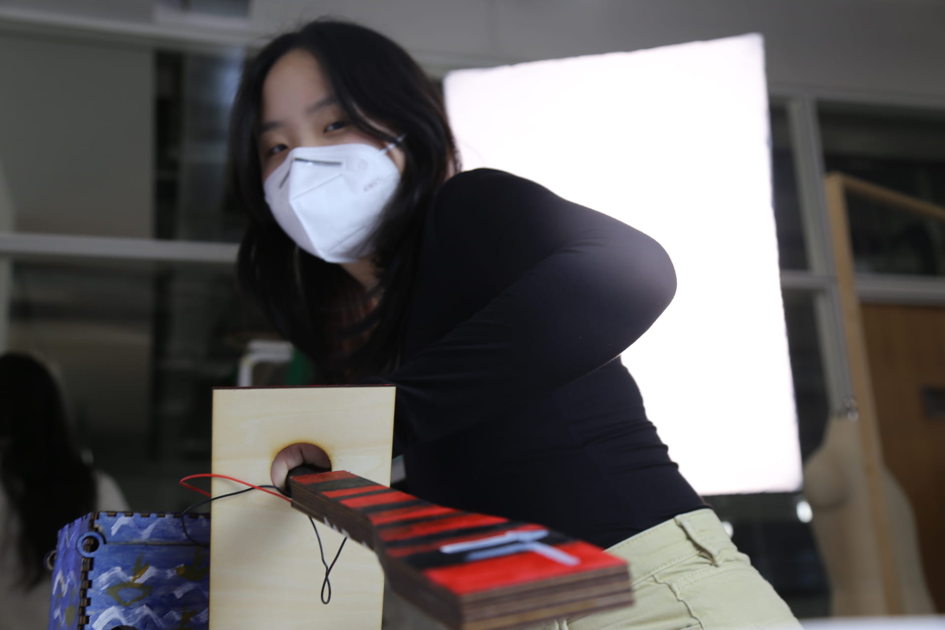
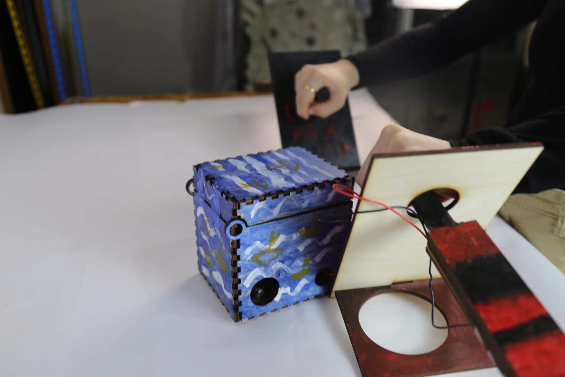
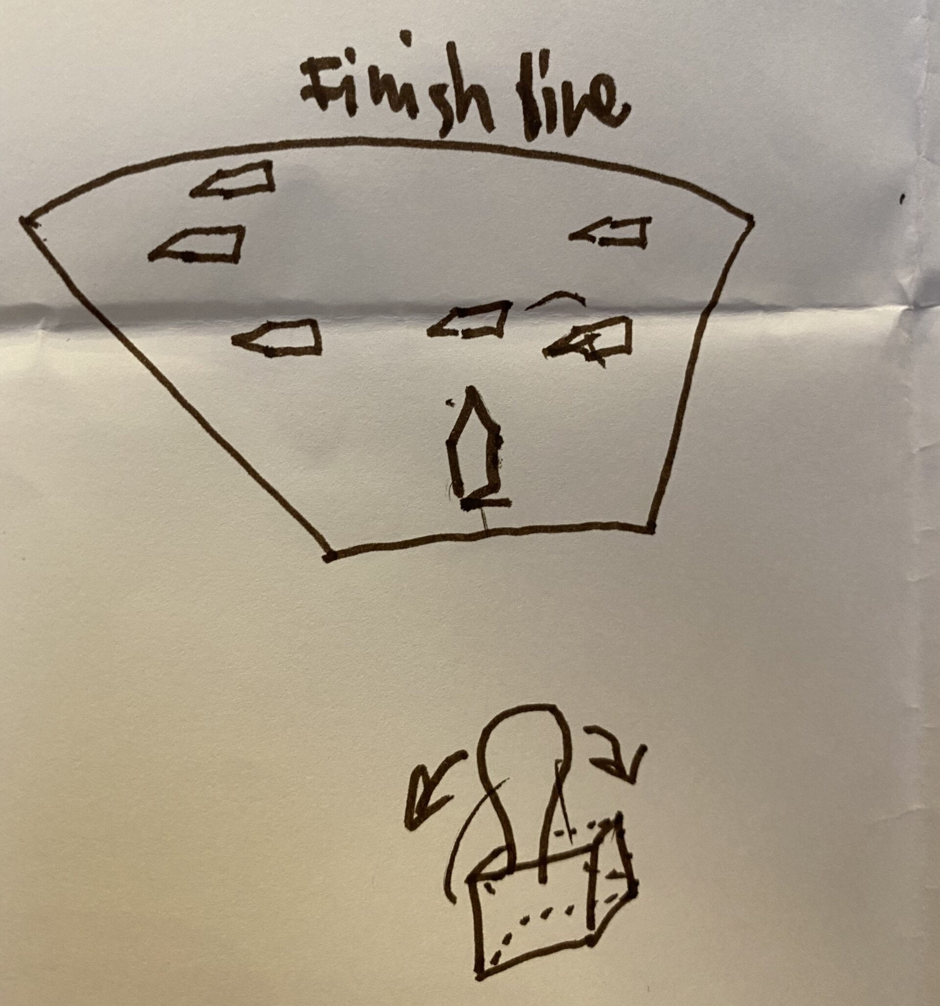
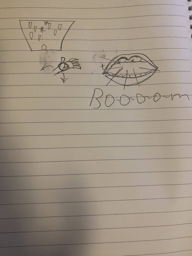
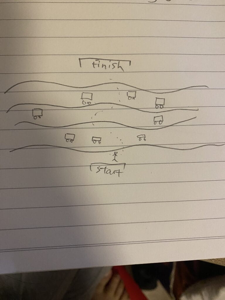
The concept of my final project is simple where a player has to avoid upcoming boats. It is inspired by an arcade game of battleship except instead of fighting the ships you’ll be of avoiding them and you do it with the help of two extremely unpredictable tilt sensors which make avoiding ships a hundred times harder. From the point of making group projects for an imaginary artifact to the midterm project until now, my concept of interaction has shifted and seen some improvement. In addition to that, I have incorporated bits and pieces of my research on the interactivity of my final project as well. I believe the readings that we have done so far helped me identify the meaning of interaction and helped me encapsulate it into the project. Especially the reading on “Making Interactive Art: Set the Stage, Then Shut Up and Listen ” by Tom Igoe has really set the tone for the design and setting of the project. For instance, during midterm, we made the project wearable so that a user gets the point of the game from the start by putting on the helmet, whereas in my final project they use oars in order to manipulate the boat on the screen. Despite going through so many ideas for actually creating the design of the controllers, I decided that paddles would be the best representation of the idea of the game. And that was because I wanted to make an imitation of a boat so the user would get the feeling they are rowing an actual boat which in return would make the game really immersive to its environment. I made each of the paddles responsible for a certain direction just like in real life if you row the right oar it moves your boat to left and if you move the left one it moves you to the right. However, in a two-dimensional game with no z-axis or an ocean that could dictate your boat I switch the sides(left to right) of the oars so it is easier for a user to get used rather than get confused during the game.

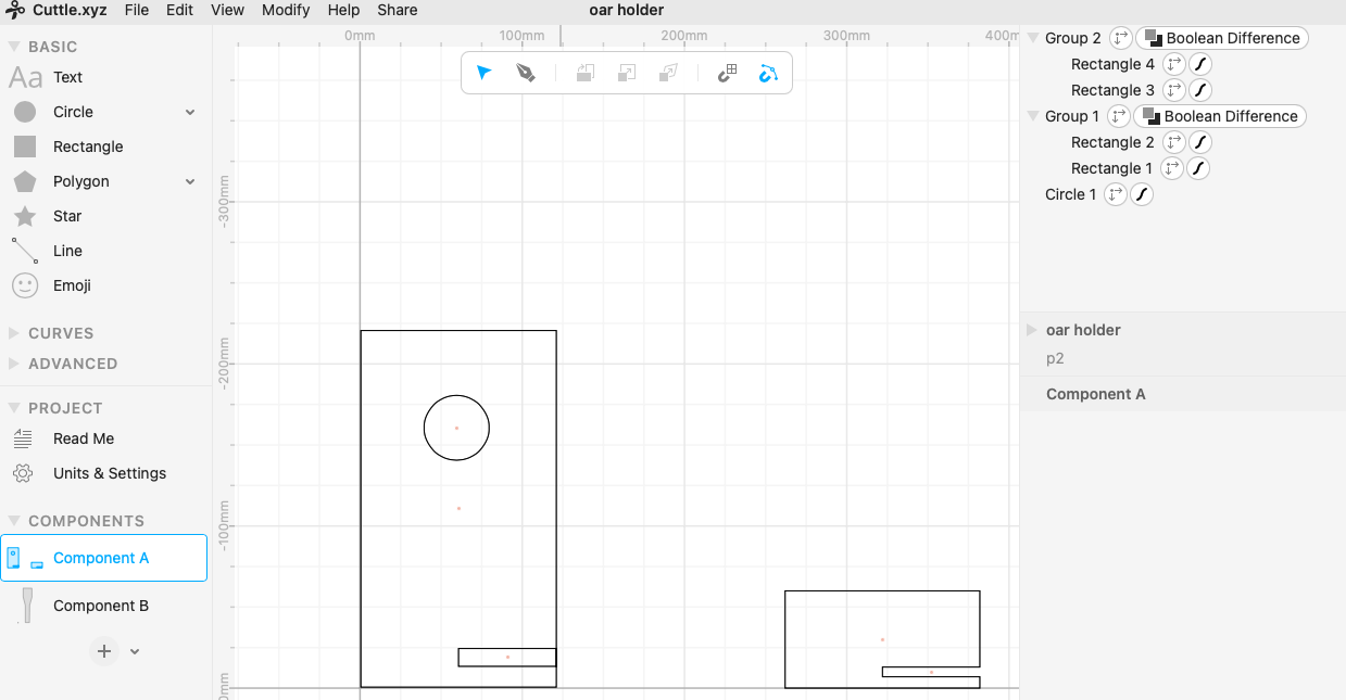
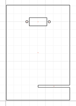
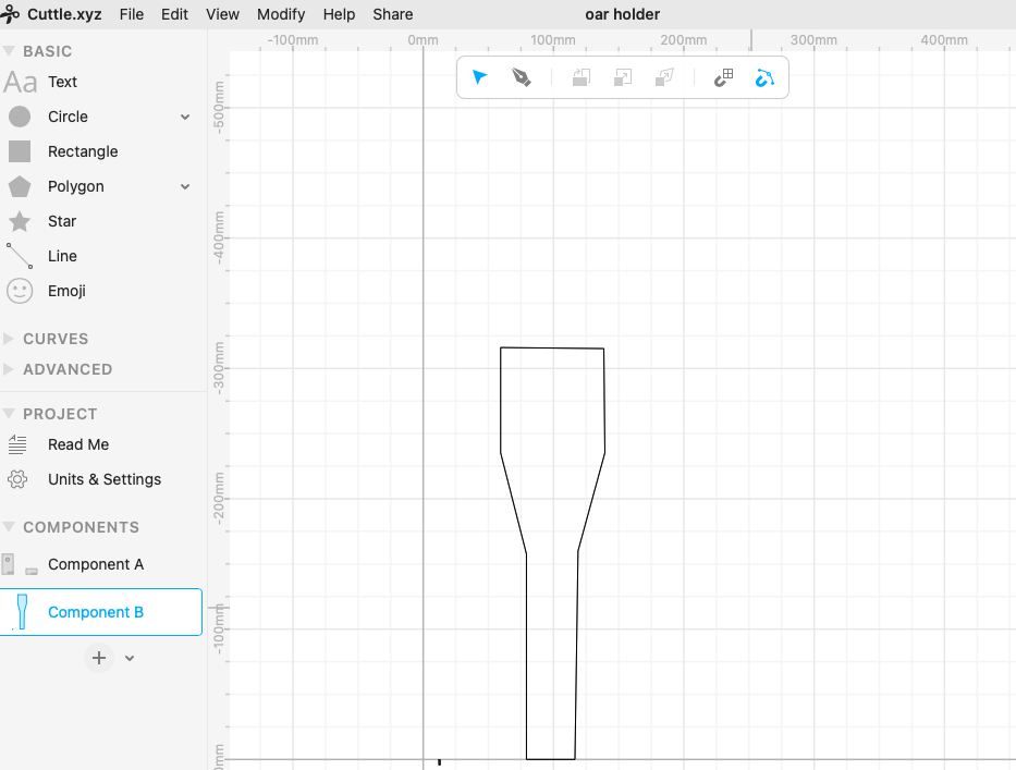
When it came to User Testing I had a couple of suggestions some were doable and others too risky to change. For starters, one user said that the oars were heavy and it would be great to make them less heavy so that it would be easier to row. I made two oar holders from both sides to make the rowing process less weighty (cuttle diagrams in Annex).
Another suggestion was that I should change the sensors, but I had only a couple of days before finals day so it would be extremely hard to pick a completely different sensor and incorporate it with the fabrication as well as coding. Although I considered a couple of other sensors from halfway it wasn’t going to be doable, especially because I wasn’t familiar with the sensors I was thinking of and I heard those sensors that we have are not really sensitive and it wouldn’t match the idea of the game. Judging from the reactions of the users to the game I noticed that it seemed a bit fast-paced and needed some sort of engaging sound so I also added a song to the game as well as a made the beginning of the game a bit simpler so instead of 10 ships coming in it would be 1 and increase from that point each round. I believe the music at the ends created a bit of a moment of distraction with the sound so that if the user loses the game they don’t feel completely discouraged from playing it again as it is meant to be a never-ending game type. Furthermore, I think it was the only thing that wasn’t making my final project presentation timing less awkward and entertaining. 

C. FABRICATION AND PRODUCTION:

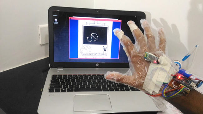
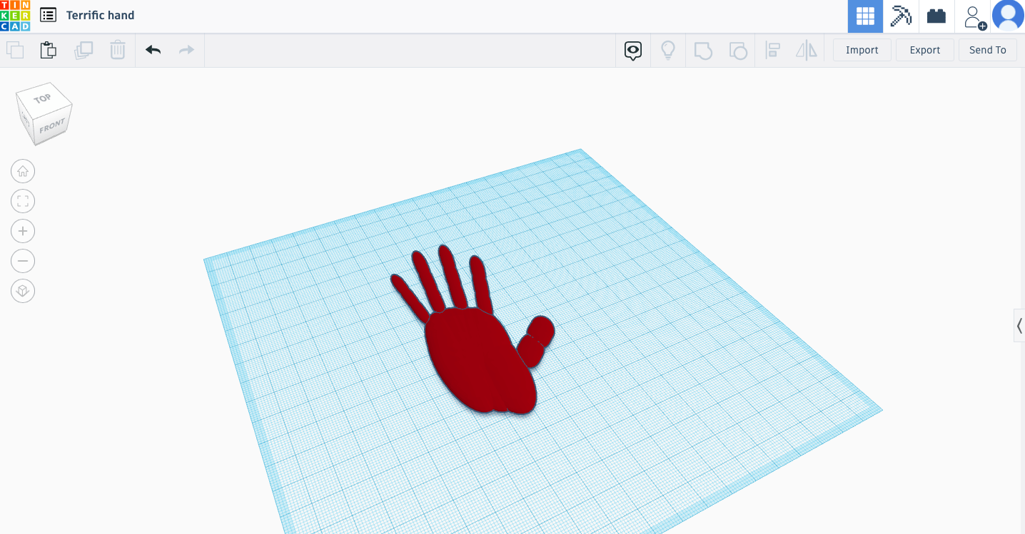
This part of the project was the most anxious but relaxing at the same time. The anxious part is the contemplation of what the fabrication is gonna be and how to accomplish it which in my case was a lot. At first, I got inspiration from amazing homemade Iron man gloves by Aswinth Raj that would control a dot on a screen and make the user able to draw with it. It was certainly a complex design to recreate even the gloves themselves which I attempted to create with a 3D printer as a thin layer on top of a hand would be able to bend.  

Here is  the design: 

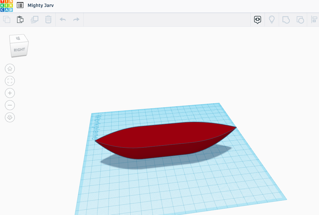
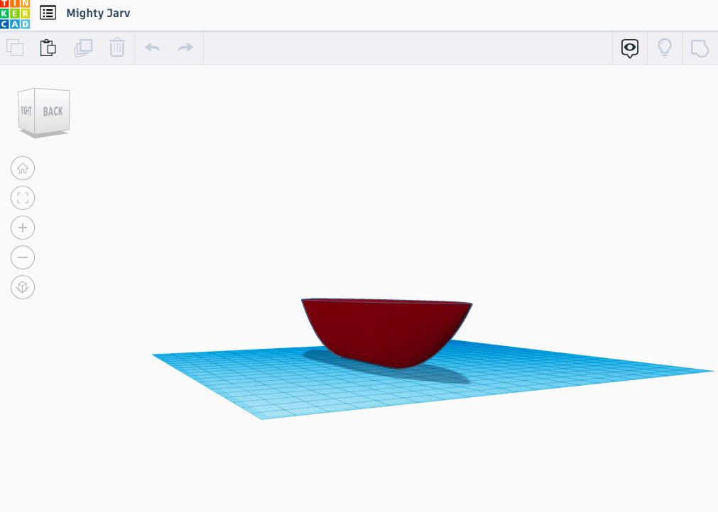
However, it would on its own already be extremely unstable, and if connected with the circuit and breadboard hard for a user to put it on let alone bend it really fast to move the boat on the screen. So, I disregarded this idea as soon as possible. The next design however for me was kind of appealing which was creating a miniature 3D boat that can hold the circuit and be moved on a surface that reminds me of water which at the time was sand. 
Here is the design of that: 

Nevertheless, it was the end of the week before finals and I already had the paddles so I decided not to go forward with it. Not mentioning the amount of time it would take to change the code. Another idea that wasn’t as immersive as the current one was creating an actual boat wheel and using potentiometers to control the boat that way. 

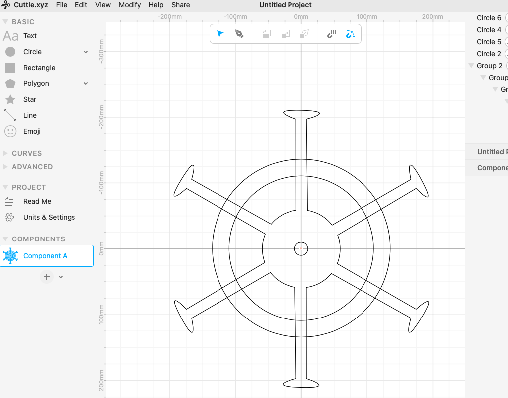
Here’s the incomplete design: 

As you can see it is not a complete cuttle design that was ready and it would make the idea of the game seem extremely generic since there are a lot of games that have wheels to play with. Therefore, I disregarded this idea too. 

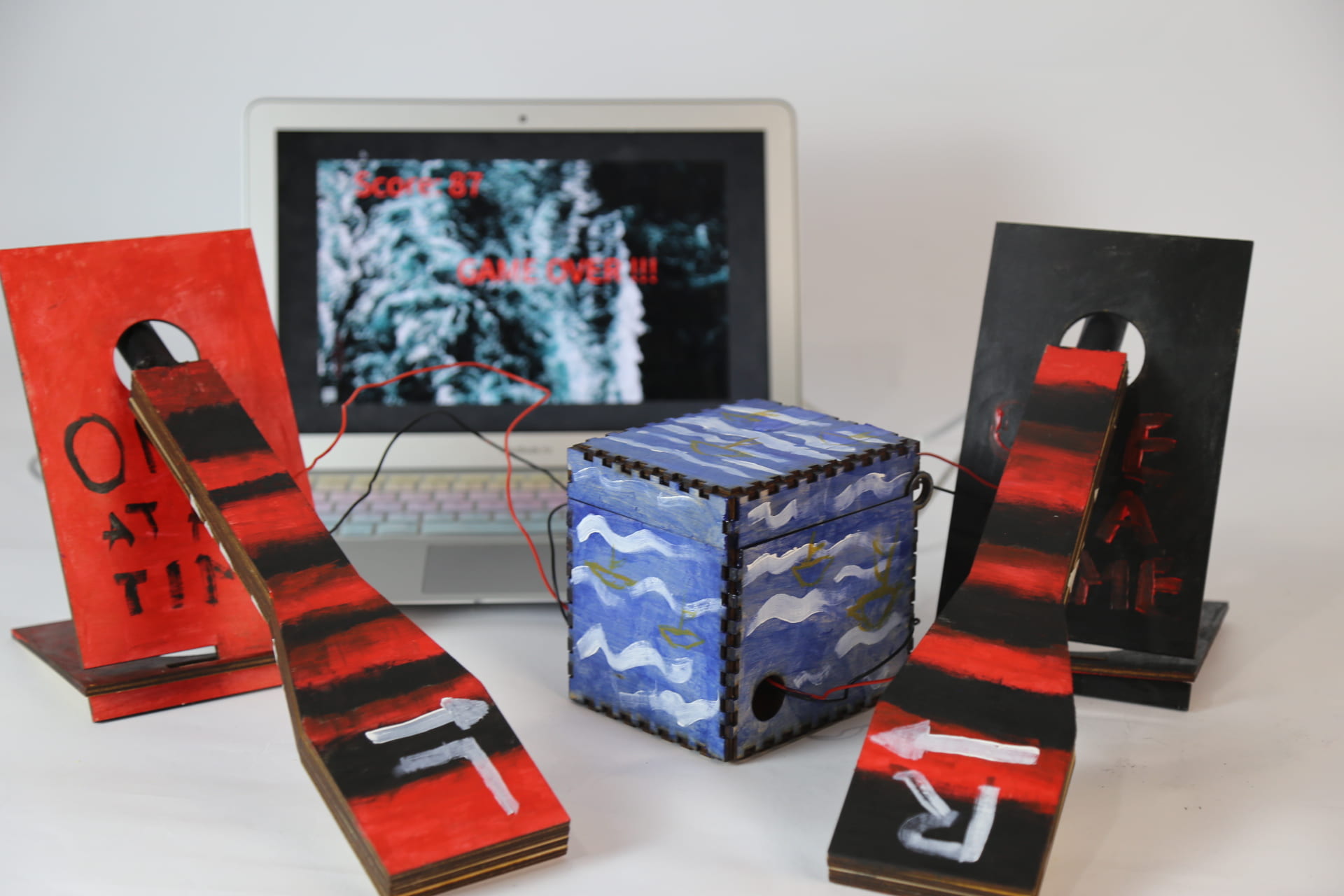
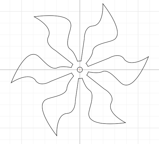
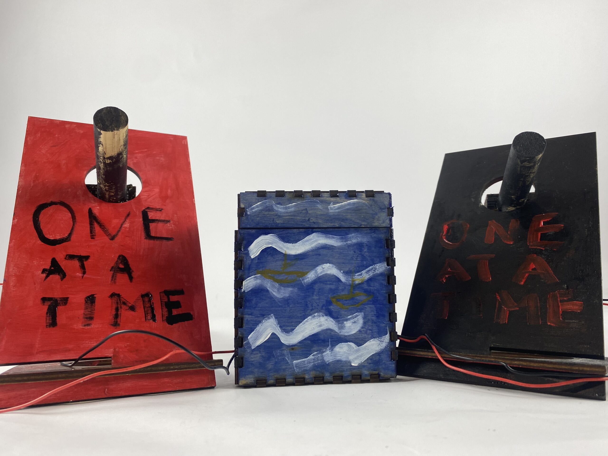
So, coming from all the failed ideas and production processes comes my final idea for fabrication which is oars and also an additional cute box to hold the circuit that gives some intrigue. So, I created the design of it using the pen and approximated the size as well as the “oar-looking” design after watching some youtube videos on how the actual oars are produced. Although they are 5 times bigger and heavier, the weight of the fabricated oars was supposed to represent that and made a bit heavy I also created the holders that illustrate the sides of the boat that hold those paddles. Moreover, the box model was taken from the sources provided by the boxes.py.  

Here’s the fab work: 

Furthermore, the inspiration behind the holders was taken from the recitation which proved to be extremely useful. At first, the holders came out to be short and the hole was too big as you can see from the video, so I adjusted the sizes one more time making it longer and making the hole a bit smaller so that the paddles won’t be wobbly when rotating.

Here’s the design of the oar:D. CONCLUSIONS:
The idea that I had from the stage research and proposal is to make a simple game without any complex, twisted logic so that the player can have fun without any unnecessary attachment or brain work which is why it is inspired by arcade games. Arcade games are the backbone of every fun game where you don’t have to sweat it if you lose because there’s an infinite amount of tries that you can do just like with flappy bird or crossroad. So, my goal was to create such a joyful ride that might be hard to win but still involves lots of fun and physical movement. I think because of the shortness of time it was hard to perfect everything, especially the predictability of the tilt sensors,  but the audience although brief had a lot of fun and played at least twice. Moreover, I think my project does align with the definition of interactivity since it goes through all three stages of processes that identify interaction: input, process, output, or even more feedback. So depending on how quickly and hard you row the paddles the more boats you avoid in the games but if you lose you’ll get a score with the game over sign and song as feedback of a lost game. Overall, despite all the fabrication lab ideas, successful or failures, it was a lot of fun creating this project. The most enjoyable and probably the most relaxing moment being the decoration of the project where I could draw and paint some boats and do random color patterns which I think came out pretty artsy. The reason why I gave it the name “Unavoidaboat” was because those boats are really hard to avoid. I tried to embrace all of its ups and falls into this name taking some positive turn instead of thinking of it as a complete failure. 

Consequently, I think my project lacks a lot of well thought or organized steps in order to give a complete work, however, the value that comes from already existing one has given a significant foundation towards more improvement. To be precise, I believe it gives a user a new perspective on the gameplay of single or two-player games with amplified psychical maneuvering and a tiny glimpse of mixed reality(MR) where a real-world object can affect what’s happening on the screen. This is a concept that I ponder a lot although I tend to not focus on it since we are still more centered around the physicality of things with circuits, however, it makes me excited that my projects, specifically the final one, are becoming more and more like those sci-fi movies which can be considered as bringing something to the table.

E. ANNEX 

1. Cuttle of the oar holders 

2. Video of the final project

3.  Interaction with the project

4. Working process

Processing code:

import processing.serial.*;
import osteele.processing.SerialRecord.*;
import processing.sound.*;
SoundFile sample;
SoundFile sample2;

Serial serialPort;
SerialRecord serialRecord;

PImage sea;
PImage ship;
PImage myship;
float shipX = 500;
float shipY = 500;
;
int shipW = 35;
int shipH =150;
//Enemy e1;
//Enemy e2;
float score;
int startnum = 10;
int level = 1;
boolean CrushShip = false;
Enemy[] enemies;

void Enemyships(int xMin, int xMax, int yMin, int yMax, int num) {
  enemies = new Enemy[num];

  for (int i = 0; i < enemies.length; i++) { 
int x = (int)random(xMin, xMax); 
int y = (int)random(yMin, yMax); 
enemies[i] = new Enemy(x, y, 100, 100); } } 

void setup() { 
// fullScreen(P2D); 
size(1200, 720); 
//background(0); 
sea = loadImage("w1.png"); 
ship = loadImage("bb2.png"); 
myship = loadImage("sh2.png"); 
Enemyships(-100, width + 20, - 250, 80, level); 
String serialPortName = SerialUtils.findArduinoPort(); 
serialPort = new Serial(this, serialPortName, 9600); 
serialRecord = new SerialRecord(this, serialPort, 2); 
//fullScreen(); // sample = new SoundFile(this, "song1.mp3"); 
sample2 = new SoundFile(this, "song2.mp3"); // sample.loop(); } 

void draw() { //tint(34,87,227);
 image(sea, 0, 0); 
line(0, 500, width, 500); 
drawPlayer(); //serialRecord.read(); 
if (!CrushShip) { moveEnemies(); if (score > startnum && score < startnum + 2) {
      Enemyships(-50, width + 20, -260, -80, level);
      level += 3;
      startnum += 10;
    }
  } else {
    text("Score: "+(int)score, 100, 100);
    text("GAME OVER !!!", width/3,height/2);
    textSize(100);
  }

  serialRecord.read();
  int value1 = serialRecord.values[0];
  int value2 = serialRecord.values[1];


  if (shipX < width-shipW) { if (value1 == 1) { //&& value1 == 0){ the right tilt shipX += 5; } } if (shipX > shipW) {
    if (value2 == 1) { //&& value2 == 1){the left tilt
      shipX += -5;
    }
  }
 println(value1,value2, shipX);


  float y0 = 0; 
  if (y0 >= 590 && y0 <= height - shipH) {
    shipY = y0;

  }

}
void moveEnemies() {
  for (int i = 0; i < enemies.length; i++) { if (enemies[i].y > height) {
      enemies[i].y = -10;
    }
    enemies[i].display();
    enemies[i].descend(random(1, 15));

    boolean XLeft = enemies[i].x + enemies[i].w >= shipX;
    boolean XRight = enemies[i].x + enemies[i].w <= shipX + shipW + 4; boolean Up = enemies[i].y >= shipY;
    boolean Down = enemies[i].y + enemies[i].h <= shipY + shipH;

    if (XLeft && XRight && Up && Down) {
      CrushShip = true;
    }
  }


  score += 0.1;

  fill(255, 0, 0);
  text("Score: "+(int)score, 10, 40);
  textSize(70);
sample2.loop();
//sample.stop();
}


void drawPlayer() {
  stroke(0);
  image(myship, shipX, shipY, shipW, shipH);
}

Arduino code:

#include "SerialRecord.h"

// Change this number to send a different number of values
SerialRecord writer(2);

void setup() {
  Serial.begin(9600);
  pinMode(2, INPUT);
  pinMode(3, INPUT);

}

void loop() {
  int sensorValue1 = digitalRead(2);
  int sensorValue2 = digitalRead(3);


  //writer[0] = millis() % 1024;
  writer[0] = sensorValue1;
    writer[1] = sensorValue2;

  writer.send();
writer.write();
  // This delay slows down the loop. This can make it easier to debug the
  // program.
  delay(10);
} 

Code References:

1. <Learn Coding From Scratch (2019), “How to make a game in Processing for any device”.Coding_For_Kids___Avoid_Blocks.pde

2. Some where taken from Processing library

Image reference:

2. BattleCruiserCommander. “Jking Crown Destroyer”. April 2020. https://forum.cosmoteer.net/d/11151-final-redford-republic-naval-update-expansion [Accessed 5 Dec. 2022]

3. Rych. “Battleship YAMATO”. June 2018. https://forum.cosmoteer.net/d/5970-ww2-ships [Accessed 5 Dec. 2022]

4. Background picture and song is copyright free


My Interaction Lab Recitation 10

GOAL

The goal of my recitation was to make a video that would change its speed depending on where potentiometer’s value is. Therefore, it would speed up the video if the value was less than 512 it would play the video faster and if less than that it would slow down or even stop the video. 

Arduino

  • This was the most straightforward part where I had to attach the jump wires to the circuit with potentiometer.
  • Here is the code:
  • #include "SerialRecord.h"
    
    SerialRecord writer(1);
    
    void setup() {
      Serial.begin(9600); 
      pinMode(A0, INPUT);
    }
    
    
    void loop() {
        int sensorValue1 = analogRead(A0);
      writer[0] = sensorValue1;
      writer.write();
      // This delay slows down the loop. This can make it easier to debug the
      // program.
      delay(10);
      //print(sensorValue1);
    
    }
    

Processing

  • This was the hardest part of the recitation to create some conditionals so that the video will react to potentiometer bending left or right by increasing or decreasing the speed of the video. 
  • Here is the code:
  • import processing.video.*;
    
    Movie film;
    
    import processing.serial.*;
    import osteele.processing.SerialRecord.*;
    
    Serial serialPort;
    SerialRecord serialRecord;
    
    void setup() {
      size(800,700);
     film =  new Movie(this, "istock-802013730_preview.mp4");
      film.loop();
      String serialPortName = SerialUtils.findArduinoPort();
      serialPort = new Serial(this, serialPortName, 9600);
      serialRecord = new SerialRecord(this, serialPort, 1);
      colorMode(RGB,360,100,0);
    }
    
    void draw() {
    
      serialRecord.read();
      int filmS = serialRecord.values[0];
    
    
      if (film.available()) {
        film.read();
      }
      image(film, 0, 0);
      if(filmS < 512){ film.speed(4.0); } if(filmS >512){
    film.speed(0.5);
    }
    
    println();
      
    }

    Here is the final work: 

My Interaction Lab Recitation 09

STEP 1. 

Design of the holder was respectfully easy because there were no complicated corners or multiple lines that needed to be considered since it’s just an rectangular shape. My teammate was Tawan and I was doing the work of a student A. 

Here is the results of the first design: 


STEP 1.2

  • This was the hardest part for me since at first I didn’t understand concept of not having multiple intersections since the laser will cut through them and the whole shape will fall apart. However, I was able to do a simple shape.

     Here is the sign of the pattern:

    STEP 2. 

  • For this step we were helped by the staff to insert the images we came up with and he turned on the laser which did all the work. 
  • An important thing that I learned during this process is the position of the material that the design will be cut on because the first time we cut the shape it wasn’t indented strong enough so it was hard to get the shape out and so the surface of the material should be straight. 

    Here is our designs being laser cut:

STEP 3. 

  • This step was pretty straightforward we just needed to attach all the parts. 
  • However we did encounter a slight problem that the whole of the outer shape was a bit smaller than of the Servo, so I think there was some miscalculation in measuring the servo or during creating of the diameter of the whole. 

    Here is the final work:


My Final Project: Essay

A. 

“Battle of ships”

B. 

I will be mainly working focused on the research mentioned in the previous blog where I have to manipulate the object on the screen with a specific sensor. The audience that I will be leaning toward is arcade game lovers that range from teens to adults. The main impact is to bring those nostalgic and simple games without any complexity back to life with a little twist. 

C. 

For the next few weeks I will be following project plan: 

  1. Create a graphic design of the game interface with Processing 
    1. Finish it by Wednesday 30th Nov
  2. Start working with Arduino to create the tilted sensor which reacts to the wrist movement from left to write
    1. Finish it by Friday, 2nd Dec
  3. Combine Arduino with Processing so they correspond to each other
    1. Finish by Monday, 5th Dec
    2. This means the ship in the Processing has to react to the movement of the the tilted sensor attack to the wrist of the player
  4. Start making the overall design of the Arduino so its not the circuit hanging out but something wearable around the wrist. Maybe gloves or bracelet that can be laser cut as well. 
    1. Finish by next Wednesday 7th Dec.

[OPTIONAL]

If I happen to finish it earlier I want to add a noice reflection which corresponds to certain noice to make bullets come out of a ship so it can destroy other ships. 

D. 

I believe the research that I have done so far helped me greatly in creation of this idea. I think what makes my project different is the fact that it is wearable unlike any other arcade came which requires some sort of consult to play with mine will not. And it will give this seamless interaction with the game like if you are inside the game. In addition, I hope to bring joy to the kids of 70s when arcade game was thriving. It is true that they are older by now but it would be an amazing reminiscing journey into childhood. Furthermore, I want to bring some value to those game that don’t really have extremely hard contextual meaning behind or a puzzle to solve or any attachment where if you die or lose you can rise up and play again without any strings attached. And I believe this will bring out the happiness in people from playing and having fun. 

My Interaction Lab Recitation 08

Task 1. 

  • At first, connecting the breadboard seemed to be the easiest part of the task, however, the uncareful placement of the jump wires did create some problems with Processing later on. Nevertheless, I think the fact that it was hardly identifiable gave a good lesson on how should I approach the task from the start. 
  • I extremely enjoyed the interaction with the circuit and the Processing as well as the results I was getting. It made me feel like Bob Ross 2.0 which you will, unfortunately, witness when watching the video of me playing with it. 

  • TASK 2. 

  • My teammate was Nicole 
  • We did have a successful ball that was bouncing, however it was extremely hard to sync it with servo. We also only had one servo which made us take a different path. 
  • And this would reflect on the interactivity of the ball, so we thought of basketball like if a player was hitting the ball and the ball was bouncing off of the ground. 
  • Here’s the video of the final work:
  • Arduino code: 
    /*
      SendMultipleValues
    
      This sketch repeatedly sends a record that contains two values:
    
      - The first value is the value of `millis()`, modulo 32768.
      - The second value is the analog value that is read from pin 9. If you attach
        a potentiometer to that pin, you can control this value by moving the pot.
    
      This sketch pairs well with the RecieveMultipleValues example from the
      Processing SerialRecord library
      <https://osteele.github.io/Processing_SerialRecord/>.
    
      Things to try:
      - Connect a second potentiometer to the Arduino, and send the values from both
        potentiometers.
      - Send the value from another sensor, such as temperature or proximity.
    
      by Oliver Steele, 2020-2022
    
      This example code is in the public domain.
    */
    #include 
    
    #include "SerialRecord.h"
    
    // Change this number to send a different number of values
    SerialRecord writer(1);
    Servo myservo;  // create servo object to control a servo
    	int pos = 0;    
    void setup() {
      Serial.begin(9600);
     myservo.attach(6);
     }
    
    void loop() {
      int sensorValue = analogRead(6);
    for (pos = 0; pos <= 90; pos += 1) { // goes from 0 degrees to 180 degrees myservo.write(pos); // tell servo to go to position in variable 'pos' delay(5); // waits 15ms for the servo to reach the position } for (pos = 180; pos >= 0; pos -= 1) { // goes from 180 degrees to 0 degrees
    	    myservo.write(pos);              // tell servo to go to position in variable 'pos'
    	    delay(5);                       // waits 15ms for the servo to reach the position	  }
      writer[0] = sensorValue;
      writer.send();
    
      // This delay slows down the loop. This can make it easier to debug the
      // program.
      delay(10);
    }
    } 

    Processing code: 

     
       float circleY;
      float xspeed = 4;
    void setup() {
      size(500, 500);
    circleY = 0;
    
    
    }
    void draw(){
        background(0);
       fill(150);
      stroke(255);
      ellipse(height/2 ,circleY ,50,50);
      circleY = circleY + xspeed;
      
      if (circleY > height){
      xspeed = -4; 
    } if (circleY< 0){
        xspeed = 4;
    }
    }
     

Final Project: Three Project Proposals

A.

       1. “Shturval” 

      2. “Perfect Pitcher”

      3. “Across the Road”

B.

1. “Shturval” is an interactive game that resembles a radar that shows multiple moving ships which you as a captain have to avoid.  Shturval translated from Russian means “a steering wheel of a boat” which would be the main tool of the game that will control the first-person ship. This game is inspired by battleship games, where you have to destroy as many enemy battleships as possible. However, the purpose of my idea is to avoid as many ships as possible. In addition, unlike most battleship games where ships move from side to side horizontally, I will make the ships move vertically, so there will be limitations in controlling the wheel of my boat. The design of the actual wheel which will be connected to Arduino will be like a traditional ship steering wheel or a control lever that bends from left to right only. The moral of the story would be to avoid conflict just like how I avoid my problems. 

2. The idea of a “Perfect Pitcher” comes from my musical background since I don’t want six years of musical school to go to waste. Nevertheless, the main point of this idea is to perfectly sing the notes or rather voice warm-up exercises (which is a series of exercises aimed to prepare the voice for singing) and replicate the given example. As you keep hitting the notes of warm-ups the pitch will go progressively higher and higher. The highest soprano voice or the lowest baritone voice will win the game. The most similar concept is Karaoke, especially games like “Smule” which gives you a score based on how well you hit the notes while singing a song. Furthermore, it might have a target audience for singers or people who enjoy singing in general. 

3. “Across the Road” is similar to the first idea the only differentiation being its original inspiration and method of gameplay. First and foremost, the genre which already exists and is the basis for this idea is the arcade, endless runner games like “Crossy Road”. The player has to cross the road without crashing into obstacles and the only difference that it has from “Shturval” is that it has more freedom of motion. Whereas in “Shrtuval” you could only left to right, in “Across the Road” you can move up and down + side to side which makes the player more flexible to its environment. However, this means that there will be more obstacles and specifications like the speed of the obstacles will be faster or they can randomly teleport so that it is hard to win the game.    

C.

  1.  

Old version: 

New version:

2. 

3.


My Interaction Lab Recitation 7


Task 1. 

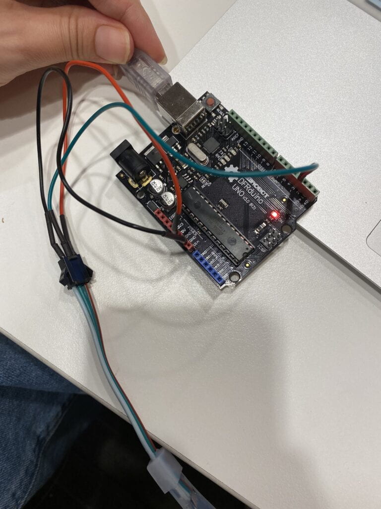
This was the most straightforward and easiest task in my opinion because we only had limited work with Arduino. We connected the LED to three different Arduino holes including ground, 5V, and pin 3 following the colors shown in the image. I’ve also successfully passed the LED test by making one light blink by going to the link examples of the Arduino FAST LED category. 

Task 2. 

I’ve also finished the second task relatively fast because we were given ready codes we needed to copy-paste, and it worked. The installation of the libraries has also been easy since we have seen how to do that before. 

Task 3. 

This was the most challenging step so far because there were too many questions on how to combine the work of an Arduino with Processing without using the same port at the same time. The step of copy-pasting one Processing code into the second one wasn’t as hard as step three where we had to add different lights to the LED. 

Task 4. 

This step made the previous one seem like child’s play. And I think without a proper image or a goal of what you want would make the task ten times harder. However, at the end of the day, I went for the same old ellipse which turned out to be a bunch of coins dancing to the beat of Harry Potter’s main theme song.

Code: 

Processing.

import processing.serial.*;
import osteele.processing.SerialRecord.*;
import processing.sound.*;

Serial serialPort;
SerialRecord serialRecord;

int W;         //width of the tiles
int NUM = 60;  //amount of pixels
int[] r = new int[NUM]; //red of each tile
int[] g = new int[NUM]; //red of each tile
int[] b = new int[NUM];


SoundFile sample;
Amplitude analysis;

void setup() {
    fullScreen();
  size(640, 480);
  W = width/NUM;

  String serialPortName = SerialUtils.findArduinoPort();
  serialPort = new Serial(this, serialPortName, 9600);
  serialRecord = new SerialRecord(this, serialPort, 4);
  serialRecord.logToCanvas(false);
  ellipseMode(CENTER);
  sample = new SoundFile(this, "Harry Potter Theme Song.mp3");
  sample.loop();
  analysis = new Amplitude(this);
  analysis.input(sample);
}

void draw() {
 background(200);
  float volume = analysis.analyze();
  int a = floor(map(volume,0,width,0,height));
  float diameter = map(volume, 0, 1, 0, width);
 for (int i=0; i<60; i ++) {
    fill(r[a], g[a], b[a]);
    ellipse(i*W+W*2, height/2, diameter/2,20) ;
  }
    r[a] = floor(random(100,255));
    g[a] = floor(random(200));
    b[a] = floor(random(90));

    serialRecord.values[0] = a; 
    serialRecord.values[1] = r[a];  
    serialRecord.values[2] = g[a]; 
    serialRecord.values[3] = b[a];  
    serialRecord.send();            
 
}
   

Arduino

 
#include "SerialRecord.h"
#include 

#define NUM_LEDS 60  // How many leds in your strip?
#define DATA_PIN 3   // Which pin are you connecting Arduino to Data In?
CRGB leds[NUM_LEDS];

// Change this number to the number of values you want to receive
SerialRecord reader(4);

void setup() {
 Serial.begin(9600);
 FastLED.addLeds<NEOPIXEL, DATA_PIN>(leds, NUM_LEDS);  // Initialize 
 FastLED.setBrightness(10); // BEWARE: external power for full (255)
 //further info at https://learn.adafruit.com/adafruit-neopixel-uberguide/powering-neopixels
}


void loop() {
 if (reader.read()) {
   for (int i = 0; i < NUM_LEDS; i += 1) {
     leds[i] = CRGB(reader[1], reader[2], reader[3]); //  Prepare the color information using CRGB( Red, Green, Blue
   FastLED.show();  //  Pass the information of color to the LED
 }
}
}

Final Project: Preparatory Research and Analysis

Inspirations. 

1.  I have looked at many interactive artifacts, but the ones that caught my attention  are mostly visual reality simulation like projects besides one project. So, I would like to start by the first and therefore most influential one, which is also been  DIYed, an “Iron man” virtual reality project by Aswinth Raj. He combined Arduino with Processing and created sort of like a virtual reality that uses magnets and Bluetooth to connect to Processing and draw on the screen. And I think this is a first home-made artifact that inspired my final project that also involves physical tool which can manipulate the objects on the screen. Despite the PS5 not reflecting the actions of the glove smoothly and completely it still does pretty good job of picking up where it started and delivering the output on the screen with a little delay. 

Image 1. Virtual Reality by Aswinth Raj . 
2. Fluid Structure 流淌的海浪 by Vincent Houzé. This is the second project which in my opinion is the embodiment of interactive artifact. It doesn’t just give you the output of the inputs at the end of the process but it shows you the output as a result of the input that you put into it on the screen. Basically, it shows the entire processing from A to B, starting from the point where you start interacting with the project until the very end of getting the image of your respectful outcomes. 

Video 1. Fluid Structure 流淌的海浪 by Vincent Houzé

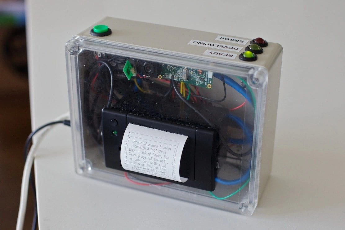
3. The Descriptive Camera by Matt Richardson takes the job of a normal camera to the next level. It might not be as visually appropriate with how regular cameras work by giving you the image of the photo captured, it still tell you more and so shows you more. As we switch our focus when we look at a photo it might divert the main context of the recorded image, which is why I believe story-oriented camera is such a treasure. It doesn’t work in the conventional way which people perceive cameras to be, it adds more colour, texture, background and feeling into the text just like how Processing does. And that is because it describes the taken image instead of giving you the image. Despite the written language being innocent or sounding like “beginner level English” it still changes our whole perspective on interactiveness of cameras. Despite it not contributing to my final project I still consider it a great representation of a successful interactive experience with an artifact. 

Image 2. The Descriptive Camera by Matt Richardson

Interaction. 

Interpretation of an interaction in my opinion can be as direct as seeing, smelling and feeling with all human senses like with our group project of creating “Perfumaker” and as indirect and as vague as touching an empty space just like with visual reality. Moreover, I think the main idea of interaction comes from the experience whether it would be during, after or before the interaction. To elaborate, you can see for instance, a glove [referencing back to the glove that can teach you how to play piano] and you start to interact with it based on your emotions of why would you need a glove, to wear it obviously, but then why and how and what purpose does it serve, etc. And while contemplating, reacting and proacting you get the sense of interaction. And I believe that is what interaction is. Even when we were user testing our “Blind man’s buff” ( “Light catcher” at the time ) the way people interacted with it through human senses and references and associating with daily life object it started making sense. This has been clearly stated by Crawford “The quality of the interaction depends on the quality of each of the subtasks (listening, thinking, and speaking)(Crawford 3).” I think this is the age we are at where virtual is slowly but steadily becoming a reality or rather physical and an interactive one at that. This has been greatly ascribed by Ernest Edmonds that interactive art systems are evolving and as does the new technologies, opportunities and capabilities of human understanding which without question commences new ideas(Edmonds 16).


References. 

  1. Crawford. “WHAT EXACTLY IS INTERACTIVITY?”, Chapter 1, pp 1-6. 
  2. Edmonds, Ernest. “Art, Interaction and Engagement”, 16 p. 

My Interaction Lab 06

RECITATION.

Screen recording of the animated poster done during class. 

Code: 

int size = 3;
int size2 = 5;
void setup() {
  size(1024, 768);
  background(0);
  colorMode(HSB, 100, 50, 9);
  drawTiles();
drawTriangle();
}

void draw() {
  
textSize(150);
fill(#080A24);
text("8",600,585);
 textSize(150);
fill(#080A24);
text("16",515,684);

   for (int y =10; y<height; y=y+50 ) {
    if (frameCount % int(random(1,30)) ==0) {
      for (int x =10; x<640; x=x+10 ) {
        fill(random(100,255), random(80), random(82));
        circle(x, y, 50);
 }
    }
  }
}
void drawTiles() {
  for (int y = 0; y<height; y= y+size) {
    for (int x = 0; x<width; x= x+size) {
      fill(random(100,200), random(70), random(190));
      rect(x, y, size, size);
    }
  }
}
void drawTriangle() {
  for (int y = 0; y<1000; y= y+size2) {
    for (int x = 0; x<800; x= x+size2) {
      fill(random(100,150), random(50), random(150));
      ellipse(x, y, size2, size2);
    }
  }

  
textSize(128);
fill(#080A24);
text("I", 800, 120);
fill(#080A24);
text("M", 800, 240);
fill(#030409);
text("A", 800, 360);
textSize(40);
pushMatrix();
text("Fall 22 ",800,420);
textSize(37);
text("End-Of-Semester Show",664,460);
textSize(80);
text("FLOOR",730,570);
textSize(50);
text("FRIDAY",730,610);
textSize(80);
text("DECEMBER",652,655); 
}  

HOMEWORK. 

I didn’t know what to create so it resulted in a completely bizarre looking animation which also acts like a game. You cannot move the mouse beyond given parameter if you do it will be a complete clash of different shapes so you have to keep the mouse in between. 

Task 1. 

I took the last circle repetition as a base of my homework animation and included two nested loops within it. 

Task 2. 

They already had random colours so I decided to keep it and added another ellipse that had 255 and 0 colours and looked up some cool animation formulas that could make it more interactive. 

Task 3.

I made it so depending on where you keep the mouse it will show the invitation text as well as change its shape and colours into something completely different. In addition, new float variable would calculate the distance between two make it seem like its changing when following the MouseX and MouseY. 

int x = 0;
int size2 = 5;
float max_distance;

void setup(){
  size(1024, 768);
  background(0);
  colorMode(HSB, 100, 50, 9);
  max_distance = dist(0, 0, width, height);

}


void draw(){
  
  if (mouseX>=400 && mouseX<=700 ) {
background(0);
textSize(128);
fill(#52C7FF);
text("I", 450, 120);
fill(#D952FF);
text("M", 450, 240);
fill(#52FFB3);
text("A", 450, 360);
  textSize(40);
  fill(#FBE8E8);
  text("Fall 22 End-Of-Semester Show", 250, 400);
  text("Location: 8th floor", 340, 450);
  text("Day: Friday December 16", 300, 500);
  text("Time: 6pm to 8pm", 340, 550); 
 
  for(int i = 0; i <= width; i += 20) {
    for(int j = 0; j <= height; j += 20) { float size = dist(mouseX, mouseY, i, j); size = size/max_distance * 66; ellipse(i, j, size, size); } } } else if(!(mouseX >=400 && mouseX<=500)){
   for (int y =1; y<height; y=y+30 ) {
    if (frameCount % int(random(20,40)) ==0) {
      for (int x =1; x<width; x=x+30 ) {
        fill(random(100,255), random(80), random(82));
        circle(x, y, 20);
      }
    }
  }

print(mouseX); 
print(" "); 
println(mouseY); 
}
} 

My Interaction Lab Recitation 05

Eiffel Tower.

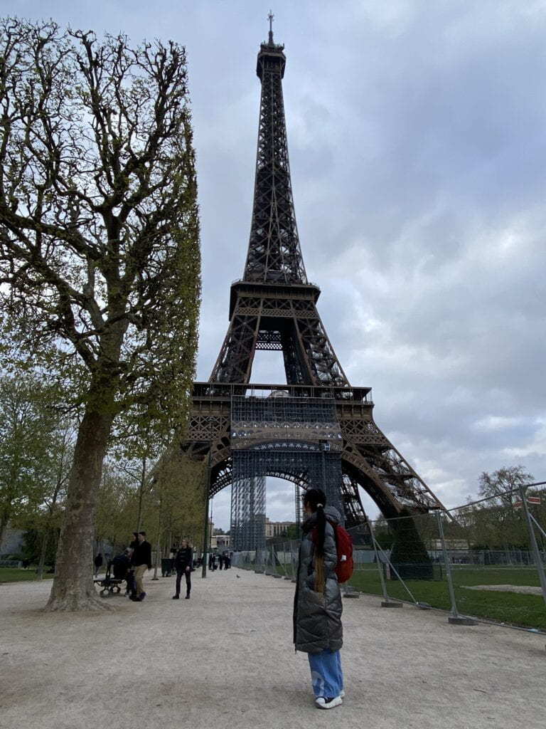
This photograph means a lot to me since it stands as a reminder of my first step into independent adulthood. Three days long trip to Paris was my first solo journey with zero knowledge of the language, people and environment.

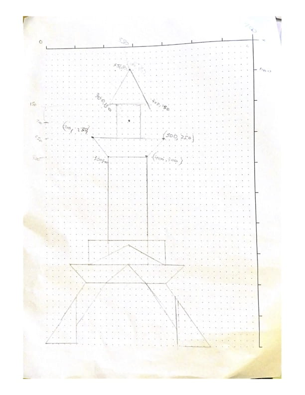
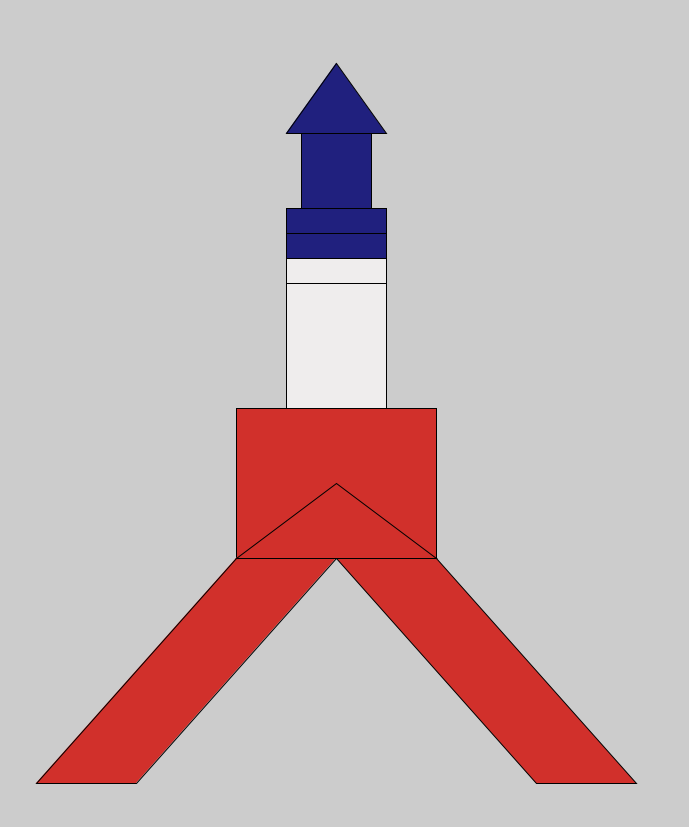
This is the actual inspiration behind the Processing drawing: 


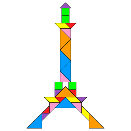
Sketch of the Processing drawing:

Process: 

At first I had a difficult sketch of the drawing, however, as I went along, I had to swap some of the shapes, because it was too difficult to code. For instance, I turned a trapezoid into a rectangle with two triangles on both sides, but then I thought that one vertically long rectangle would suffice. Because if you look at the live version of the Eiffel Tower, it doesn’t have any trapezoid at the top, just some kind of cubic gaps between the vertical rectangle. I think painting with Processing was definitely more challenging, however, once you get the hang of it, it will be quite useful, especially when playing with colors.

Final drawing: 

Code:

mvoid setup() { rectMode(CENTER); size(900, 1500); fill(#20207E); // canvas //triangle(120, 300, 232, 80, 344, 300); triangle(300, 150, 350, 80, 400, 150); rect(350, 200, 70, 100); rect(350,250,100, 50); rect(350,300,100,100); fill(#EFEDED); rect(350,350,100, 150); rect(350,400,100, 200); fill(#D1302B); rect(350,500,200,150); triangle(250, 575, 450, 575, 350, 500); quad(350, 575, 450, 575, 650, 800, 550, 800); quad(350, 575, 250, 575, 50, 800, 150, 800); } void draw(){ print(mouseX); print(" "); println(mouseY); }