Digital Game Physical Prize | Nina Chen | Gottfried
Concept Ideas:
When thinking of what to do for this project, all I had thought of are all arcade games. This was due to during that week, my friends and I often went out to play in arcades.
So, I came up with three concepts: 


Within these three ideas, I was the most gravitated towards the claw machine idea since I really like the idea of being able to make a claw machine game to my own liking.
Furthermore, since one of this project’s requirement was to use either the 3D printer or the laser cutter, claw machine was the best candidate overall.
Design:
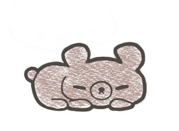
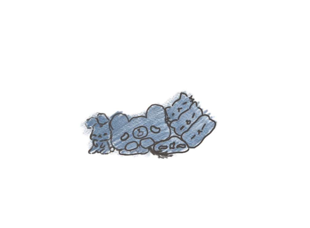
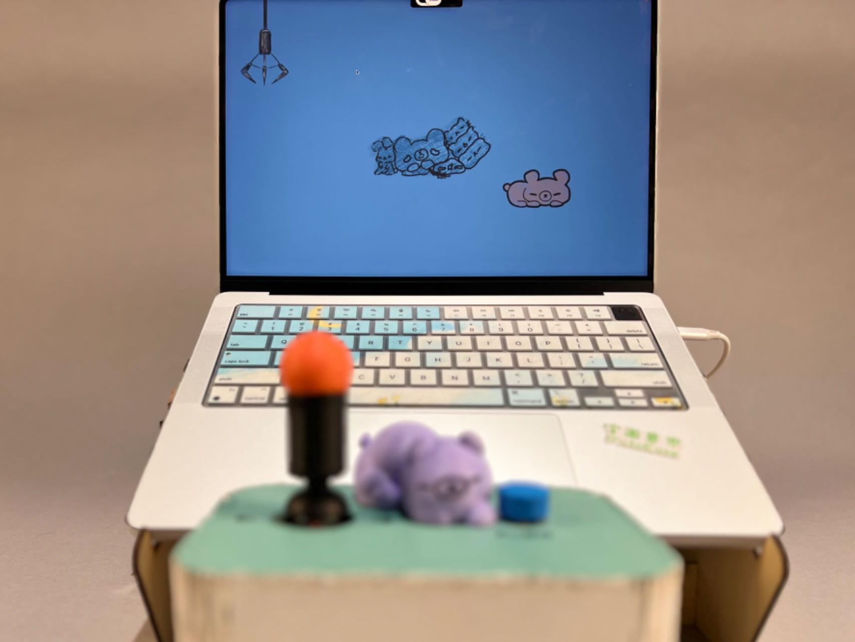
For the design of this claw machine, I decided to hand draw the open claw, close claw, close claw with bear, bear drop, bear rest, bear return, and plush stack background.


For the rest of the proposal write-up, I split it into three parts:
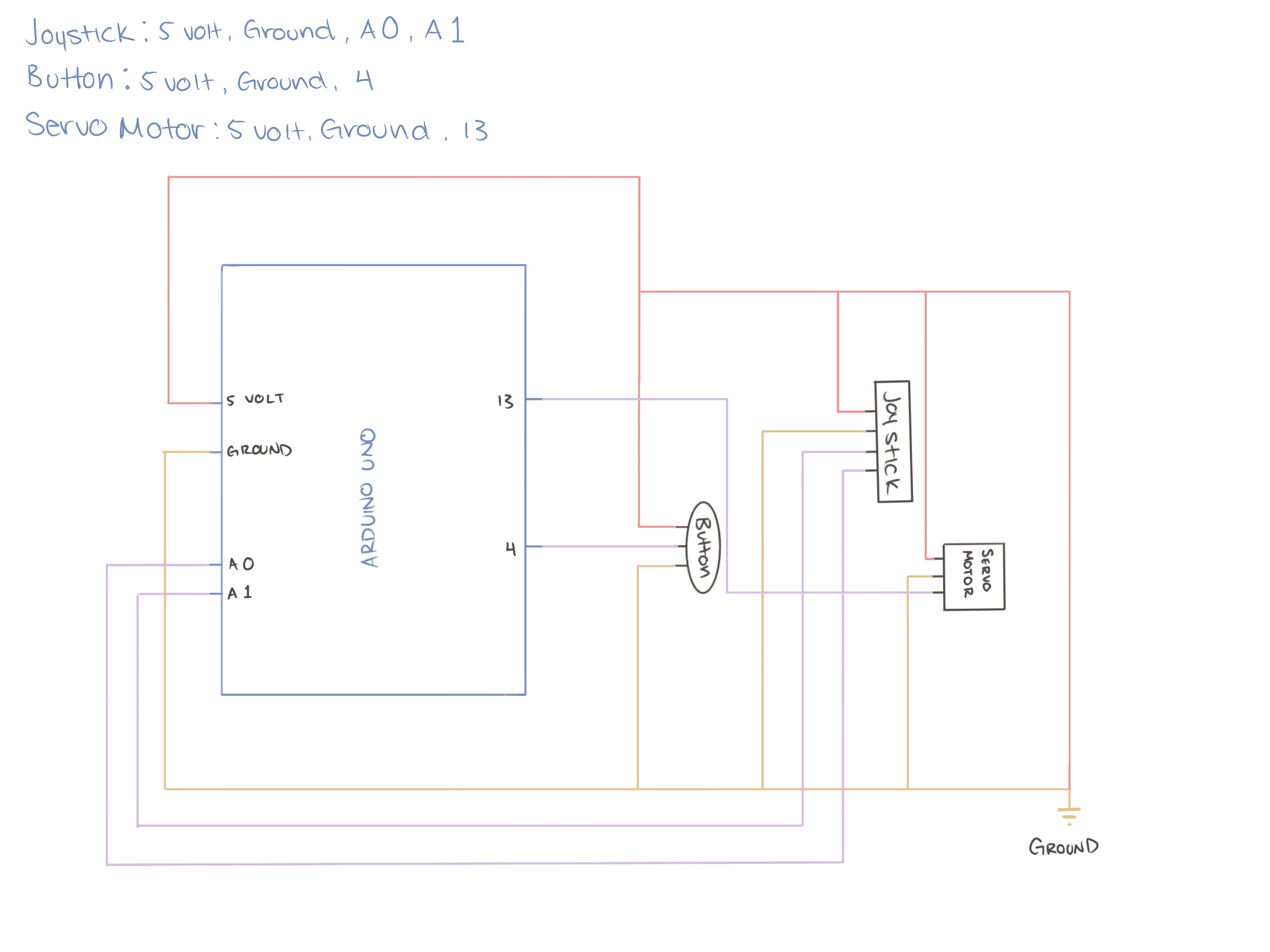
- Arduino Codes and Wirings
- Processing Codes, connecting to arduino, and images
- Connecting processing to arduino, exterior design, 3D print bears, and motor for close and release bear when captured
More in depth concept:


User Test:
During the user test, I had only gotten the claw close and claw open, however I hadn’t gotten the claw grab bear down yet. It was also at the user test that I got the recommendations to add a background and make sure the claw can grab the bear. I was also recommended to add background music and adding a claw moving sound as well. All of the above recommendations are taken into account in the final product.
Fabrication and Production:
Production of the project was pretty smooth in terms of time management since I had already had each step planned out. Originally I thought that figuring out the first step is going to take a week but in fact it only took around two days since majority of the code can be found online. The issue kicked in when I was working on the processing side. This was because in order for processing to use the serial from arduino, it has to be numbers. The code I had for arduino didn’t send in numbers, but instead it was up, down, left, and right.
After that was fixed, I had realized later on that I did not need to use up and down since it wasn’t in my intention for the user to be able to control the height of the claw. Nonetheless, the code for up and down was removed and replaced with different a code that controls it’s up and down movement when the button is pressed and goes up when the claw reaches a certain y-value.
While I had a plan for how long each section would take along with the order that for the different parts of the project, I did not strictly follow the order I set for myself. This was because I find it easier to work on the other sections when I got stuck with a section of the code. It was kind of a way to take my attention away from just staring at the code and still be able to process what to add while being productive by working on the exterior.
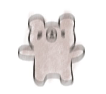
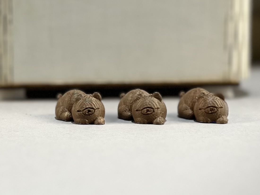
Originally, I planned to find a model online that is similar to my design since I had thought that it shouldn’t be hard to find a 3D sleeping bear model. However, I was wrong, I didn’t have any luck in finding a 3D model that fits so I modeled my own during one of those coding breaks:

While it was a slight annoyance to make the bear, it was also therapeutic at the same time.
A concept that I ended up dropping was a the random second timer where once it reaches it, the claw automatically drops the bear (as show in video below):
This was ultimately dropped since I didn’t know how to incorporate it with the other code for the claw goes up, and returns to starting position.
As for the music portion, I wanted it to be a calming piano piece for the start since I find that it fits the most with the sleeping bear atmosphere. The issue was, since it’s an audio piece, processing took extra long to load. Thus I settle for a much shorter part of the piece that can still looping nicely.
After the starting music has been implemented, I chose a different audio file that fits for a claw machine. As expected, the issue of the claw move audio ended up overlapping each other and resulted in a very jagged sound. Given that I had tried multiple ways to solve this and led to no conclusions, I asked for help from Kevin, our TA.
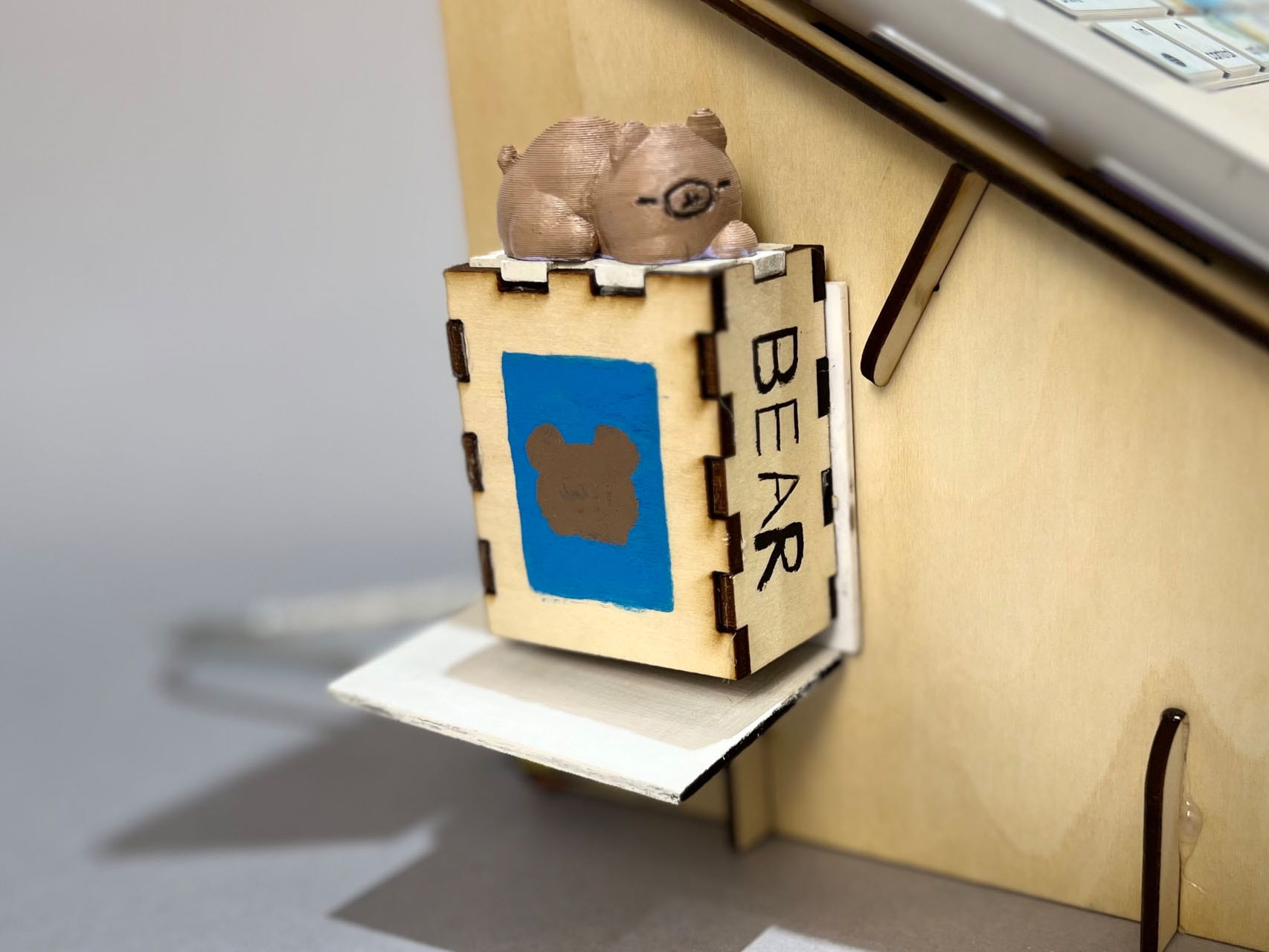
Returning back to arduino, I had forgotten how to link the serial data from processing to arduino. To address the precise issue I had ran into, arduino was indeed able to receive date from processing, but it wasn’t able to do anything else with the data it was getting. The result I wished for was when arduino receives the data, the servo motor would open the contraption for the bear that I had printed out as prize to drop. In order to get this issue sorted, I asked for assistance from our professor, Gottfried. He explained that it would be easier for me to set the data receive to a certain degree that I wish for the servo motor to turn and that was it.
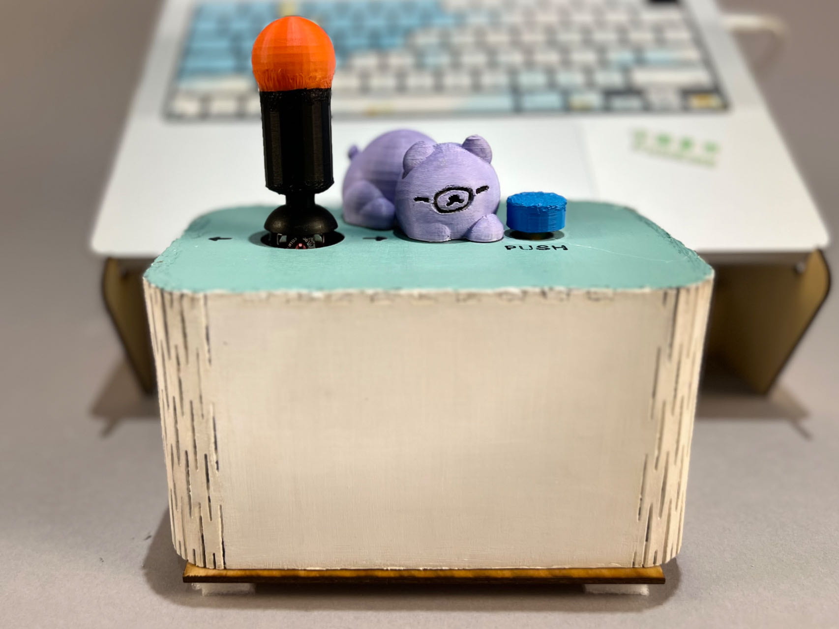
Finally, the exterior. It’s worth mentioning that the original plan was to make the exterior like an arcade machine. However, due to the time left, I opted for the next best idea which was to make a stand for my laptop so that the screen is elevated.
Final Presentation and After Thoughts:
For the final presentation, everything work as intended. However, I do wish that I could have made it a lot more interesting. Unlike an actual claw machine, the winning for this makeshift claw machine was 100%. There wasn’t a single chance of being able to miss it, unless the user’s aim was undeniably terrible, or they wanted to test what would have happened if they deliberately missed.
One suggestion I would like to implement next time is the different stages like Andy, another professor of IxLab, has suggested. The first stage can be kept the same, however stage 2 would add probability of success rate and stage 3 would be the bear running away from the claw. While these two stages would add difficulty, it is still in my intent that the success rate for grabbing the toy is 100% possible. I would also like to implement the random second drop mechanism if I am able to work on this project again.
Going back to user testing, a suggestion I got was adding multiple different types of prizes so that the player can choose which one they would like.
All in all I was unable to add these suggestions and recommendation for a better experience since these are all currently out of my knowledge of code and abilities..
Delighted Situations:
- Seeing the code work as I wish
- User’s reaction to a physical prize popping out from the side
- Overall cuteness
- The small animation for return back to screen:
Videos and Final Images:
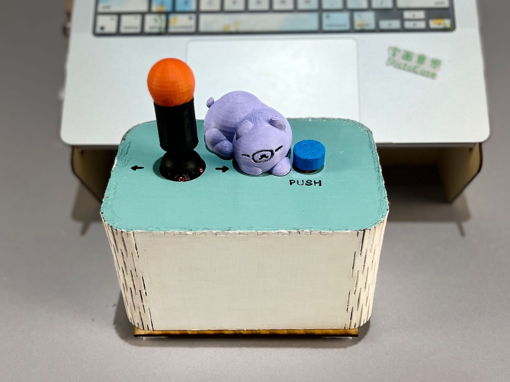
Other Notes:
Special thanks to:
- Gottfried (Professor)
- Andy (Professor)
- Dalin (3D + Laser Cut)
- Shengli (TA)
- Kevin (TA)
- Eric (Student)
- Kyle (Student
- Evan (Student)
- Zora (Student)
- Jae (Student)
Along with more for suggestions, recommendations, coding assistance, and patience with me on this project. Also my gratitude to all of those who helped test my project throughout the process.
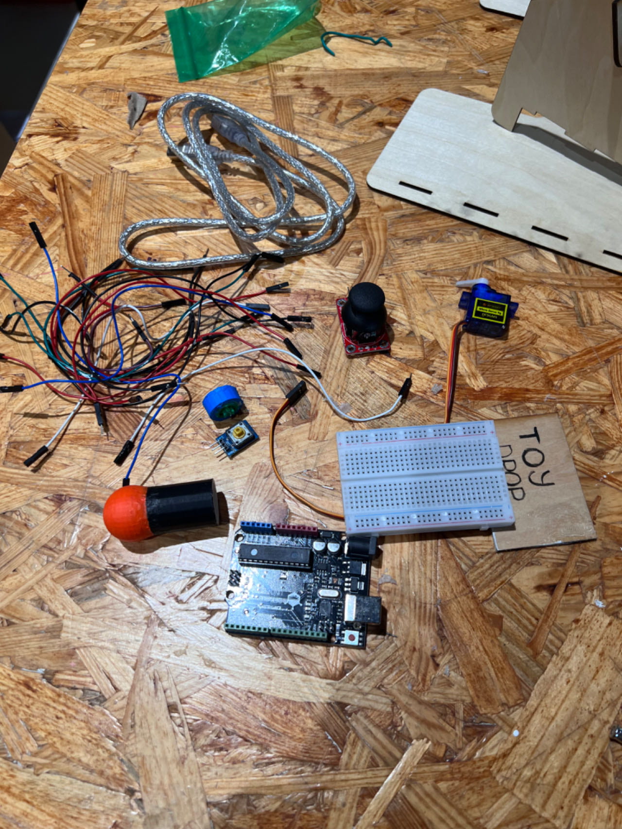
Disassembly:
Appendix:
Joystick Arduino Reference:
“Arduino – Joystick: Arduino Tutorial.” Arduino Getting Started, 7 Dec. 2023, arduinogetstarted.com/tutorials/arduino-joystick.
Arduino Code:
#include <Servo.h>
Processing Code:
import processing.serial.*;
import processing.video.*;
import processing.sound.*;
Serial serialPort;
int NUM_OF_VALUES_FROM_ARDUINO = 3;
int arduino_values[] = new int[NUM_OF_VALUES_FROM_ARDUINO];
import processing.serial.*;
int NUM_OF_VALUES_FROM_PROCESSING = 1;
int processing_values[] = new int[NUM_OF_VALUES_FROM_PROCESSING];
float x = 300;
float y = 300;
float bx = 950;
float by = 520;
PImage img;
PImage img2;
PImage img3;
PImage img4;
PImage img5;
PImage bg;
Movie myMovie;
SoundFile sound;
SoundFile mySound;
void setup() {
//size(1023, 1023);
fullScreen();
background(137, 162, 188);
bg = loadImage (“bg plushes.png”);
img = loadImage (“sleep bear.png”);
img2 = loadImage (“claw.png”);
img3 = loadImage (“claw closed.png”);
img4 = loadImage (“claw closed with bear.png”);
img5 = loadImage (“fall.png”);
myMovie = new Movie(this, “bear walk sleep.mp4”);
myMovie.play();
sound = new SoundFile(this, “claw noise.mp3”);
mySound = new SoundFile(this, “start.mp3”);
mySound.loop();
printArray(Serial.list());
// put the name of the serial port your Arduino is connected
// to in the line below – this should be the same as you’re
// using in the “Port” menu in the Arduino IDE
serialPort = new Serial(this, “/dev/cu.usbmodem21101”, 9600);
}
int clawState = 1;
int clawClosedAt = -1;
boolean grabbedToy = false;
boolean armmove = false;
void draw() {
//scale(0.5);
println(clawState + ” ” + x + ” ” + y);
background(134, 158, 185);
image(bg, 250, 120);
stroke(255);
fill(255);
// receive the values from Arduino
getSerialData();
//claw goes down if PRESSED
if (clawState == 1) {
if (!mySound.isPlaying() && !sound.isPlaying()) {
mySound.loop();
}
image(img2, x – 250, y – 1100);
image(img, bx, by);
if (myMovie.available()) {
myMovie.read();
}
if (myMovie.time() < myMovie.duration()) {
image(myMovie, bx + 7, by – 229);
}
if (arduino_values[1] == 2) {
x = x – 3;
mySound.stop();
if(!sound.isPlaying()) {
sound.loop();
}
} else if (arduino_values[1] == 1) {
x = x + 6;
mySound.stop();
if(!sound.isPlaying()) {
sound.loop();
}
}
else {
sound.stop();
}
// possible transitions:
if (arduino_values[0] == 1) {
clawState = 2;
}
} else if (clawState == 2) {
image(img2, x – 250, y – 1100);
image(img, bx, by);
if (myMovie.available()) {
myMovie.read();
}
if (myMovie.time() < myMovie.duration()) {
image(myMovie, bx + 7, by – 229);
}
mySound.stop();
if(!sound.isPlaying()) {
sound.loop();
}
y = y + 5;
if (y >= 620) {
clawState = 3;
clawClosedAt = millis();
}
} else if (clawState == 3) {
image(img3, x – 250, y – 1100);
image(img, bx, by);
mySound.stop();
if(!sound.isPlaying()) {
sound.loop();
}
if (arduino_values[1] == 1) {
x = x – 3;
mySound.stop();
if(!sound.isPlaying()) {
sound.loop();
}
} else if (arduino_values[1] == 2) {
x = x + 2;
mySound.stop();
if(!sound.isPlaying()) {
sound.loop();
}
}
if (arduino_values[0] == 0) {
if (y <= 630 && y > by – 215) {
y = y – 5;
mySound.stop();
if(!sound.isPlaying()) {
sound.loop();
}
}
if (y >= by – 220) {
if (x <= bx + 120 && x >= bx – 650) {
x = x – 5;
clawState = 4;
mySound.stop();
if(!sound.isPlaying()) {
sound.loop();
}
}
}
}
// possible transitions:
if (x – 250 >= bx – 40 && x – 250 <= bx + 180) {
clawState = 4;
//bx=x-300;
grabbedToy = true;
}
if (millis()-clawClosedAt > random(3000, 7000)) {
clawState = 1;
clawClosedAt = -1;
grabbedToy = false;
}
} else if (clawState == 4) {
if (grabbedToy == true) {
image(img4, x – 250, y – 1100);
} else {
image(img3, x – 250, y – 1100);
image(img, bx, by);
}
if (y > 300) {
y = y – 4;
mySound.stop();
if(!sound.isPlaying()) {
sound.loop();
}
} else {
clawState = 5;
}
} else if (clawState == 5) {
if (grabbedToy == true) {
image(img4, x – 250, y – 1100);
} else {
image(img3, x – 250, y – 1100);
image(img, bx, by);
}
if (x > 300) {
x = x – 4;
} else {
if (grabbedToy == true) {
clawState = 6;
bx = -25;
by = 150;
} else {
clawState = 1;
}
}
} else if (clawState == 6) {
image(img2, x – 250, y – 1100);
image(img5, bx, by – 35);
sound.stop();
if (by < height) {
if (by > 550){
processing_values[0] = 1;
}
by = by + 7;
} else {
clawState = 1;
bx=950;
by= 520;
myMovie.jump(0.0);
myMovie.play();
processing_values[0] = 0;
sound.stop();
mySound.loop();
}
}
sendSerialData();
}
// the helper function below receives the values from Arduino
// in the “arduino_values” array from a connected Arduino
// running the “serial_AtoP_arduino” sketch
// (You won’t need to change this code.)
void getSerialData() {
while (serialPort.available() > 0) {
String in = serialPort.readStringUntil( 10 ); // 10 = ‘\n’ Linefeed in ASCII
if (in != null) {
//print(“From Arduino: ” + in);
String[] serialInArray = split(trim(in), “,”);
if (serialInArray.length == NUM_OF_VALUES_FROM_ARDUINO) {
for (int i=0; i<serialInArray.length; i++) {
arduino_values[i] = int(serialInArray[i]);
}
}
}
}
}
void sendSerialData() {
String data = “”;
for (int i=0; i<processing_values.length; i++) {
data += processing_values[i];
// if i is less than the index number of the last element in the values array
if (i < processing_values.length-1) {
data += “,”; // add splitter character “,” between each values element
}
// if it is the last element in the values array
else {
data += “\n”; // add the end of data character linefeed “\n”
}
}
// write to Arduino
serialPort.write(data);
print(“To Arduino: ” + data); // this prints to the console the values going to arduino
}
Circuit Diagram
