Echo From The Ancient
– Weiyi Lu(Livvy)&Leo – Instructor: Inmi
CONTEXT AND SIGNIFICANCE
In Reading Analysis1, I wrote, “Interaction is an action where two sides respond to each other naturally and spontaneously.” Animas – Music co-creation with AI aligns with my definition of interaction because it is able to generate musical sequences in response to user inputs and changes. In my previous project Kinetic Wearable, we designed a set of “Social Batteries” that shows the user’s social energy level by detecting the ambient light, and simply convey the concept of interaction through the input of the user’s action and the output of energy level. Both of them helped me improve my understanding of interaction for my midterm project.
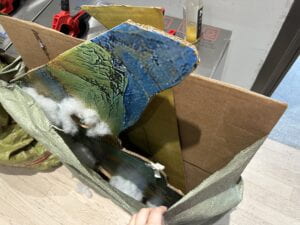
What is significant about our project is the concept of bringing a painting to life. We chose the famous Chinese ancient painting “Thousand Li of Rivers and Mountains” as the prototype of our project. This painting is a representative of Chinese art. It combines the serene beauty and profound depth of China’s natural landscapes, showing that the art can not just convey visual splendor but also emotional and philosophical depth. Our targeted audience is the general public, especially university students and scholars. In today’s fast-paced world, our project creates a space of meditation. Since most people nowadays are looking more into the future and prospects of humans and less focused on human traditional cultures, we want to offer an escape from the busy modern life, inviting participants to find a sense of inner peace.
CONCEPTION AND DESIGN
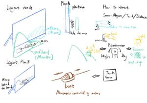
We want the audience to find the interactive elements hidden in the stationary painting, and then try to interact with it to make the painting “moving”.
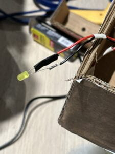
The potentiometer serves as the LEDs and the light controller, adjusting their brightness to simulate environmental changes in scenes. The LEDs act as the lights in residents’ homes at night, while the light(3W High-Power Keyes LED Module with PCB Chassis for Arduino STM32 AVR) acts as the sun in the sky. When the audience knob the potentiometer clockwise, it represents the trace of the sun and moon, showing the change of day and night by adjusting the brightness of those two components.
In addition, We purchased shiny silk fabric to mimic rivers. When the wind blows, represented by the symbolic pictures on the magnet servo, the servo motors stuck on the cardboard start to rotate their arms back and forth, pulling the fabric to imitate the effect of running water gushing in the wind. We also created a boat on the river to move when the rivers are flowing.
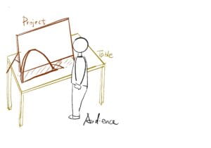
Below are the original drafts of our designs.
FABRICATION AND PRODUCTION
During our production process, from my point of view, our most successful aspect lies in the look of our project, meeting the audience’s aesthetic needs. To maximize the audience experience, we made our project large enough to impress them and engage several people to appreciate it together. More importantly, the four servo motors pull the fabric at different angles in different positions, making its movement and appearance beautiful in the light. However, I think we failed to integrate interactive elements into the look and feel while keeping the viewer aware of how to interact without using obvious cues. And this problem occurred in the user testing session. Several audiences couldn’t recognize the magnet sensor and its function, so they didn’t know how to interact with the project. Also, the potentiometer was not obvious. To make the interactive elements more intuitive, on one hand, we printed the images of the sun and moon to visualize the day-and-night hint. On the other hand, we followed Professor Inmi’s suggestion and created a circular slot in the painting that the viewer could recognize and place the circular piece of cardboard with the magnet in it, realizing the interaction. Unfortunately, although we tried our best to balance the looking and the intuition by creating the slot and sticking the same picture of waves, the user in our presentation still couldn’t recognize it immediately, and we need to improve this problem in future projects. In addition, I adjusted the movement of the boat to make it move more naturally by rewriting the code of the stepper motor due to fellow Kevin’s advice in User Testing. Finally, it worked better than previous.
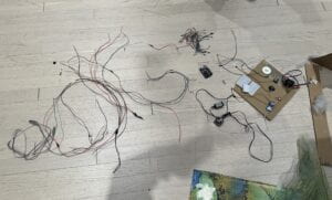
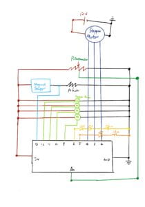
Personally, I designed the circuit diagram and connected all components with the help of Leo’s soldering long wires. The biggest problem of this part is loose or defective wire contact. We sometimes found the project didn’t work because one of the wires came off the breadboard. Another problem was that we forgot to use insulating tape, causing the positive and negative poles of the LED lights to touch together and not light up properly. Thanks to Professor Andy for pointing out it.
Also, I was mainly responsible for the Arduino code because I had coding experience in cclab last semester. Most parts worked well, especially the usage of millis() instead of delay() to let all components work together. However, I found it hard to control the stepper motor to make it rotate back and forth in the same trace every time I plug in the battery because it doesn’t have a default position, unlike stepper motors, so I spent a lot of time to adjust my code. Professor Andy suggested that I could set up a final position for it every time it finishes moving so that we can create the zero position manually by fixing the motor’s arm before it starts to rotate. Moreover, we need to change the plastic cap of the stepper motor before the presentation because its heat baked the flat surfaces. Professor Gottfried advised us to use a screwdriver to adjust the components on the panel to make it cooler when operating.
Here is the origin code, using delay(), but can only run the servo motors.
void loop() {

  // Rotate from 0 to 180 degrees
  for (int angle = 0; angle <= 180; angle++) { servo1.write(angle); servo2.write(angle); servo3.write(angle); servo4.write(angle); delay(15); } delay(100); for (int angle = 180; angle >= 0; angle--) {
    servo1.write(angle);
    servo2.write(angle);
    servo3.write(angle);
    servo4.write(angle);
    delay(15);
  }

  delay(100);
}
Here is the version using millis() to rotate the servo motors, but I could not achieve the day-and-night effect.
void loop() {
  unsigned long currentMillis = millis();

  // Update servo position smoothly
  if (currentMillis - oldMillis > 15) {
    angle += speed;
    if (angle <= 0 || angle >= 180) {
      speed = -speed;
      angle += speed;
    }

    servo1.write(angle);
    servo2.write(angle);
    servo3.write(angle);
    servo4.write(angle);

    oldMillis = currentMillis;
  }

  int potValue = analogRead(potPin);
  int lightBrightness = map(potValue, 0, 511, 100, 0);
  int ledBrightness = map(potValue, 511, 1023, 0, 255);
  if (potValue >= 0 && potValue < 511) { analogWrite(lightPin, lightBrightness); } if (potValue > 511 && potValue <= 1023) {
    analogWrite(ledPin, ledBrightness);
  }

}
So I need to make the digital output zero at last to achieve light control like this version.
  if(potValue < 511){
    // Light up the light, and make sure LED is turned off
    int lightBrightness = map(potValue, 0, 511, 255, 0);
    analogWrite(lightPin, lightBrightness);
    analogWrite(ledPin, 0); // Turn off LED
  } else {
    // Light up the LED, and make sure light is turned off
    int ledBrightness = map(potValue, 511, 1023, 0, 255);
    analogWrite(ledPin, ledBrightness);
    analogWrite(lightPin, 0); // Turn off light
  }
The magent sensor and the stepper motors are added. When the magnet state is high, the servo motors and the stepper motors start to rotate. This is the version for the User Test.
void loop() {
  unsigned long currentMillis = millis();

  int magnetState = digitalRead(magnet);

  if (magnetState == HIGH) {
    if (stepper.distanceToGo() == 0) {
      stepper.moveTo(stepperPositions[targetPosIndex]);
      targetPosIndex ^= 1;
    }
    stepper.run();

    if (currentMillis - oldMillis > 15) {
      angle += speed;
      if (angle <= 0 || angle >= 180) {
        speed = -speed;
        angle += speed;
      }

      servo1.write(angle);
      servo2.write(angle);
      servo3.write(angle);
      servo4.write(angle);

      oldMillis = currentMillis;
    }
  }
Below is the final version of all the code, including adding the movement of going back to the origin zero position of the stepper motor to control its trace.
#include

int angle = 0;
int speed = 2;
unsigned long oldMillis = 0;
Servo servo1;
Servo servo2;
Servo servo3;
Servo servo4;

int DIR_PIN = 2;
int STEP_PIN = 3;
int EN_PIN = 4;
AccelStepper stepper(AccelStepper::DRIVER, STEP_PIN, DIR_PIN);

int ledPin = 6;
int lightPin = 5;
int potPin = A0;
int magnet = 13;

long stepperPositions[2] = { 30, 60 };
int targetPosIndex = 0;
bool stepperMoving = false;

void setup() {
  pinMode(EN_PIN, OUTPUT);
  digitalWrite(EN_PIN, LOW);
  stepper.setMaxSpeed(2000);
  stepper.setAcceleration(1000);
  stepper.setSpeed(1000);

  servo1.attach(9);
  servo2.attach(10);
  servo3.attach(11);
  servo4.attach(12);
  pinMode(ledPin, OUTPUT);
  pinMode(lightPin, OUTPUT);
  pinMode(magnet, INPUT);
  Serial.begin(9600);

  // Move the stepper to a known start position at setup
  stepper.setCurrentPosition(0);
  stepper.moveTo(stepperPositions[0]);
  while (stepper.distanceToGo() != 0) {
    stepper.run();  // Block until stepper reaches the target position
  }
}

void loop() {
  unsigned long currentMillis = millis();

  // Read the state of the magnet
  int magnetState = digitalRead(magnet);

  if (magnetState == HIGH) {
    //Move stepper motor between two positions
    if (stepper.distanceToGo() == 0) {
      // Change target position once the current target is reached
      stepper.moveTo(stepperPositions[targetPosIndex]);
      targetPosIndex ^= 1;
    }
    stepper.run();

    // Update servo position smoothly
    if (currentMillis - oldMillis > 15) {
      angle += speed;
      if (angle <= 0 || angle >= 180) {
        speed = -speed;
        angle += speed;
      }

      servo1.write(angle);
      servo2.write(angle);
      servo3.write(angle);
      servo4.write(angle);

      oldMillis = currentMillis;
    }
  } else {

    stepper.moveTo(0);
    stepper.run();
  }

  // Control logic for LED and light based on potentiometer value
  int potValue = analogRead(potPin);
  if (potValue < 511) {
    int lightBrightness = map(potValue, 0, 511, 255, 0);
    analogWrite(lightPin, lightBrightness);
    analogWrite(ledPin, 0);  // Turn off LED
  } else {
    int ledBrightness = map(potValue, 511, 1023, 0, 255);
    analogWrite(ledPin, ledBrightness);
    analogWrite(lightPin, 0);  // Turn off light
  }

  // Optional: Serial prints for debugging
  Serial.print("Potentiometer Value: ");
  Serial.println(potValue);
}
Here is the circuit diagram
Leo was mainly responsible for handmake tasks such as cutting cardboard and assembling them.
CONCLUSIONS
The goal of our project is to provide the audiences with a temporary break from the hustle and bustle of reality, letting them enjoy the beauty and serenity of landscapes from nearly a thousand years ago. What aligns with my definition of interaction is that our project managed to create an environment for the audience and itself to have a “conversation” in heart with each other. Nevertheless, what does not align with my definition of interaction is that the project’s interactive responses are simple and can’t generate different outcomes according to the audience’s input. The audience can control the light of day and night by knobing the potentiometer and putting the board in the slot to move the fabric and the boat. I might improve our project by using sensors and making the outcomes changes according to the various inputs if I had more time. Also, the mechanism design of the boat movement could be improved. In conclusion, I have learned from my project that it’s important to design the interaction part to allow the audience to interact with your work for as long as possible, which is my future improvement, while the aesthetic appearance is also crucial, which is what I achieved in this project.
DISASSEMBLY