Author: Ruiyang Chen
Real-time Media Video Performance System Patcher
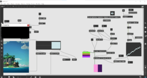
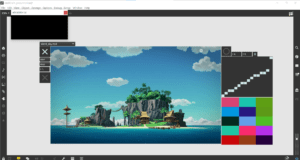
In this system, I used the previous Video Playback System. I combined it with some new things——the eclipse object in Max 8. So, I’m able to compose the image captured by camera of the videos in a folder. Then, I created a toggle to sequence through the video automatically, thus the combined image is also changed.
Edit mode:
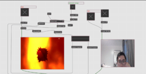
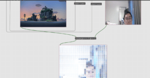
Presentation mode:
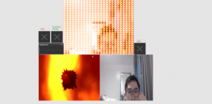
Video:
Real-time Media Video Playback System
My theme is about scenery and mood, by using some nature beauties I can show how calm I am, or I can show chaos using a pulsating sphere. I change one thing in the project from the class, so that I can go through the videos in a folder in sequence instead of randomly. On the right part, I build a system that can generate random graphs according to the dimension we set. I can also change the graph I want to play and the sequence of them. A new object “jit.world” is used here, but I’m not well understand of its function.
Video:
Edit:
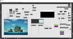
Presentation:
IMA Real-time Media hw3 Two Sound Player
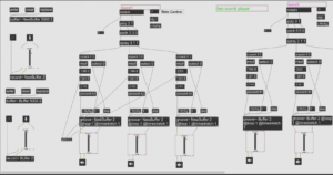
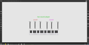
Based on the audio player created in class, I created the Two Sound Player. I first looked at the patcher from class, where the we can press the piano key to control the pitch of the sound we previously recorded. I then considered whether it is possible to play two different sound at the same time. So, I added one more buffer to store a new sound and I also discovered that the old piano keyboard can control it successfully. I believe it is feasible to build more buffers, so that more sounds can be played, but that would be to caotic. Next, I will show the Two Sound Player in edit and presentation mode.
Edit mode:
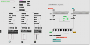
Presentation mode:
Real-time Media hw2: Piano Autoplayer
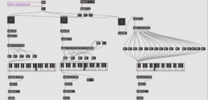
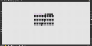
Based on what we learned at class, I made a Piano Autoplayer that can choose from three melodies that I created. Pressing the ‘stop’ sign can halt the music. The three melodies are as follows: melody1: an edited music originated from Rachel; melody2: twinkle twinkle little star; melody3: chord 6415. I made threee ksliders so that it won’t crush with each other, though it may be a little complex. I used the unmenu to change the melody users want to play, but one thing I failed to do is to created a start button. Next, I will show you the Piano Autoplayer in presentation and edit mode.
Video:
Edit mode:
Presentation mode:
Real-time Media hw1 patcher
I started learning Max8 using the video on youtube. Following the instructions was not a hard task, but it is quite challenging to do things from scratch by myself. So, I made some changes to the time patcher created following the video tutorial. I added another swatch controller and change the led background color for each options——10 seconds, 20 seconds and 60 seconds. There are also some problems that I failed to solve: how to change the light of LED with swatch, which I tried really hard, since in the LED it says Hilited LED color, but I just couldn’t change it; why the counter goes up to 1000 after one round (this is quite wierd). All in all, this learning experience is relaxing and full of fun, it is always refreshing to look at something you build and feel the accomplishment.
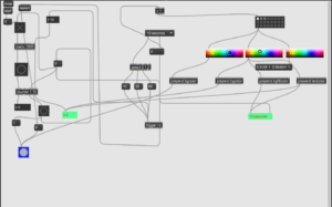
Next, I’ll show how this time patcher works in presentation mode and in edit mode.
The Boundless Light-Leon Chen-Professor Gottfried Haider
Concept and design:
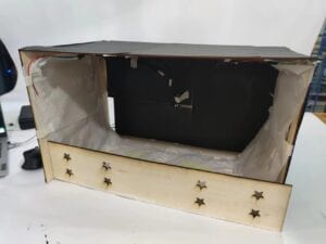
My project derived from the Infinite Mirror Room in the “teamLab Borderless Shanghai”. The room in the museum has countless light where each of them can link to another light and make a unique route. The mirror in the room reflects the light and makes the room a dream-like space. I also want to provide my users a fantastic experience through light. Besides, I read the article “Art, Interaction and Engagement” by Ernest Edmonds, in which he concluded a way of interaction is “relating” that provokes long-term interest in the users (12). I think the best way to achieve this is to make my project more artistic, just as the Infinite Mirror Room does. But I’m not going to build a room, instead, I decided to put neopixels in a box to achieve the effect. The purpose of my project is to allow users to click the mouse on Processing to make neopixels light up, which may give them an unforgettable experience. The light of neopixels appears as if it was boundless. During the user testing, I recieved suggestions on the exposion of neopixels in the box and the user interface problems. Therefore, I used some rice paper to cover up the neopixels, on the other hand, these paper are transparent so that light can come through. I also made more areas on the Processing for the user to click and expanded the interface area to the whole screen. I was also suggested to integrate the screen into the box, but since I’ve finished fabrication, it would be time-consuming to do this. Professor Gottfried adviced me to allow user to choose what color they want to distribute. However, this function would require an array in an array, which was beyond my abillity.
Fabricationa and Production:
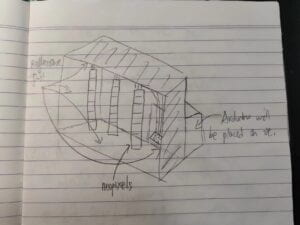
As for the fabrication, I originally decided to build the project according to the sketch above. I soon realized that neopixels were too long to be hung like that way, otherwise the box would be like a tall building, which was stupid. Therefore, I changed my plan and draw another sketch. But why did I choose neopixels? On one hand, it is long enough to exhibit the change of light colors. On the other hand, neopixels will make the difficulty of my project moderate. I once thought of using multiple LEDs to do the task, but they were small and thin, which were not something I wanted for my final project.
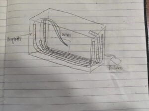
The wiring was rather simple, because I didn’t choose any sensors. On the contrary, the most difficult part was the coding. I initially used multiple states to control the neopixels with the number sent by the Processing.
Arduino:
#include <FastLED.h>
#include "SerialRecord.h"
SerialRecord reader(1);
int value;
#define NUM_LEDS 30  // How many leds on your strip?
#define DATA_PIN1 3
CRGB leds1[NUM_LEDS];
CRGB leds2[NUM_LEDS];
CRGB leds3[NUM_LEDS];
SerialRecord writer(1);
int state = 0;


void setup() {
  Serial.begin(9600);
  FastLED.addLeds<NEOPIXEL, DATA_PIN1>(leds1, NUM_LEDS);
  FastLED.addLeds<NEOPIXEL, 5>(leds2, NUM_LEDS);
  FastLED.addLeds<NEOPIXEL, 10>(leds3, NUM_LEDS);
}
void state0() {
  for (int i = 0; i < 30; i = i + 1) {
    leds1[i] = CRGB(0, 0, 0);
    leds2[i] = CRGB(0, 0, 0);
    leds3[i] = CRGB(0, 0, 0);
  }
  writer[0] = state;
  writer.send();
  delay(10);
  FastLED.show();
  if (reader.read()) {
    value = reader[0];
    //Serial.println(value);
    if (value == 1) {
      state = 2;
    }
    if (value == 2) {
      state = 3;
    }
    if (value == 3) {
      state = 4;
    }
  }
}
void state1() {
  for (int i = 0; i < 30; i = i + 1) {
    leds2[i] = CRGB(i, 10, 0);
    FastLED.show();
  }
  state =0;
}

void state2() {
  // LED1
  for (int i = 0; i < 30; i = i + 1) {
    leds1[i] = CRGB(10, 0, 0);
    FastLED.show();
    delay(50);
  }
  writer[0] = 1;
  writer.send();
  delay(10);
  state = 0;
}
void state3() {
  //LED2
  for (int i = 0; i < 30; i = i + 1) {
    leds2[i] = CRGB(0, 10, 0);
    FastLED.show();
    delay(50);
  }
  writer[0] = 2;
  writer.send();
  delay(10);
  state = 0;
}
//LED3
void state4() {
  for (int i = 0; i < 30; i = i + 1) {
    leds3[i] = CRGB(0, 0, 10);
    FastLED.show();
    delay(50);
  }
  writer[0] = 3;
  writer.send();
  delay(10);
  state = 0;
}
void loop() {
  if (state == 1) {
    state1();
  } else if (state == 2) {
    state2();
  } else if (state == 3) {
    state3();
  } else if (state == 4) {
    state4();
  } else {
    state0();
  }
  Serial.println(state);
}
Processing:
import processing.serial.*;
import osteele.processing.SerialRecord.*;
Serial serialPort;
SerialRecord serialRecord;


void setup(){
  size(600,600);
  //fullScreen();
  String serialPortName = SerialUtils.findArduinoPort();
  serialPort = new Serial(this, serialPortName, 9600);
  serialRecord = new SerialRecord(this, serialPort,1);
}

int lastSend = 0;

void draw(){
  background(0);
  fill(255);
  stroke(0);
  circle(mouseX,mouseY,50);
}

void mousePressed(){
  if (mouseX<200 && mouseX>0){
      serialRecord.values[0]=1;
    } else if (mouseX>=200 && mouseX<400){
      serialRecord.values[0]=2;
    }else{
      serialRecord.values[0]=3;
    }
   //println(frameCount, serialRecord.values[0]);
   serialRecord.send();
}
It totally failed beacuse I couldn’t control the neopixels.
Maybe this was because of the complexity of the code, so I simplified the code and tried agian. This time the neopixels lighted up correctly, but it would went wrong if I clicked twice or more.
Arduino (simplified):
#include <FastLED.h>
#include "SerialRecord.h"
SerialRecord reader(3);
int value;
#define NUM_LEDS 58  // How many leds on your strip?
#define DATA_PIN1 3
CRGB leds1[NUM_LEDS];
CRGB leds2[NUM_LEDS];
CRGB leds3[NUM_LEDS];
//SerialRecord writer(3);
void setup() {
  Serial.begin(9600);
  FastLED.addLeds<NEOPIXEL, DATA_PIN1>(leds1, NUM_LEDS);
  FastLED.addLeds<NEOPIXEL, 5>(leds2, NUM_LEDS);
  FastLED.addLeds<NEOPIXEL, 10>(leds3, NUM_LEDS);
}
void loop() {
  if (reader.read()) {

    value = reader[0];
    //Serial.println(value);
    if (value==1) {
      for (int i = 0; i < 58; i = i + 1) {
        leds1[i] = CRGB(10, i, 0);
        FastLED.show();
        delay(50);
      }
      for (int i = 0; i <58; i = i + 1) {
        leds1[i] = CRGB(0, 0, 0);
        FastLED.show();
      }
    } else if (value==2) {
      for (int i = 0; i < 58; i = i + 1) {
        leds2[i] = CRGB(i, 10, 0);
        FastLED.show();
        delay(50);
      }
      for (int i = 0; i < 58; i = i + 1) {
        leds2[i] = CRGB(0, 0, 0);
        FastLED.show();
      }
    } else if (value==3) {
      for (int i = 0; i < 58; i = i + 1) {
        leds3[i] = CRGB(i, 0, 10);
        FastLED.show();
        delay(50);
      }
      for (int i = 0; i < 58; i = i + 1) {
        leds3[i] = CRGB(0, 0, 0);
        FastLED.show();
      }
    }
  }
}
I consulted Professor Gottfried for help, he changed the value I sent from a number to an array that store the times I clicked. The Arduino then do the if condition multiple times to fulfill the number in the array.
Arduino:
#include <FastLED.h>
#include "SerialRecord.h"
SerialRecord reader(3);
int value;
#define NUM_LEDS 58  // How many leds on your strip?
#define DATA_PIN1 3
CRGB leds1[NUM_LEDS];
CRGB leds2[NUM_LEDS];
CRGB leds3[NUM_LEDS];

int completed[3];

void setup() {
  Serial.begin(9600);
  FastLED.addLeds<NEOPIXEL, DATA_PIN1>(leds1, NUM_LEDS);
  FastLED.addLeds<NEOPIXEL, 5>(leds2, NUM_LEDS);
  FastLED.addLeds<NEOPIXEL, 10>(leds3, NUM_LEDS);
}
void loop() {
  if (reader.read()) {

    value = reader[0];
    //Serial.println(value);
    if (completed[0] < reader[0]) {
      for (int i = 0; i < 58; i = i + 1) {
        leds1[i] = CRGB(10, i, 0);
        FastLED.show();
        delay(50);
      }
      for (int i = 0; i <58; i = i + 1) {
        leds1[i] = CRGB(0, 0, 0);
        FastLED.show();
      }
      completed[0]++;
    } else if (completed[1] < reader[1]) {
      for (int i = 0; i < 58; i = i + 1) {
        leds2[i] = CRGB(i, 10, 0);
        FastLED.show();
        delay(50);
      }
      for (int i = 0; i < 58; i = i + 1) {
        leds2[i] = CRGB(0, 0, 0);
        FastLED.show();
      }
      completed[1]++;
    } else if (completed[2] < reader[2]) {
      for (int i = 0; i < 58; i = i + 1) {
        leds3[i] = CRGB(i, 0, 10);
        FastLED.show();
        delay(50);
      }
      for (int i = 0; i < 58; i = i + 1) {
        leds3[i] = CRGB(0, 0, 0);
        FastLED.show();
      }
      completed[2]++;
    }
  }
}
Processing:
import processing.serial.*;
import osteele.processing.SerialRecord.*;
Serial serialPort;
SerialRecord serialRecord;

int[] count = new int[3];

void setup(){
  size(600,600);
  String serialPortName = SerialUtils.findArduinoPort();
  serialPort = new Serial(this, serialPortName, 9600);
  serialRecord = new SerialRecord(this, serialPort,3);
}

int lastSend = 0;

void draw(){
  background(0);
  fill(255);
  stroke(0);
  circle(mouseX,mouseY,50);

  if (millis()-lastSend > 200) {
    serialRecord.write(count);
    printArray(count);
  }
}

void mousePressed(){
  if (mouseX<200 && mouseX>0){
     count[0]++;
    } else if (mouseX>=200 && mouseX<400){
      count[1]++;
    }else{
      count[2]++;
    }
}
This modification may seem unimportant, but if my purpose is to give my users an immersive and unforgettable experience, I need to allow them to click wherever and whatever they want. It proved that I was right when my classmates tried my project in the final testing.
The laser cutting appeared more difficult than I thought. On one hand, I overestimate the hole I made for the wires, so I later used cardboard to seal the hole.
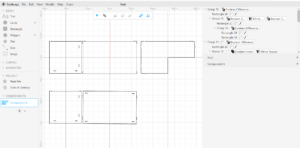
On the other hand, the sketch looked quite nice, but it turned out that there were two layers, therefore, some of the prominent parts were cut down. I had to use hot glue gun to stick them together. After the user testing, I found that the inside of the box was not dark enough to achive the desired effect, so I immediately made a front board.
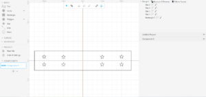
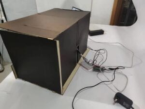
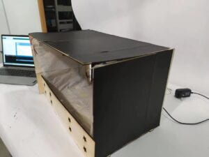
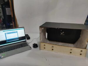
I also attached many black papers inside and outside the box to make a room manually. The final result looked like this
Conclusions:
The purpose of my project is give users an unforgettable experiecen throught the exploration of light patterns of neopixels. I think my project has accomplished the goal. I initially expected them to slowly explore and view the pattern that neopixel displayed. But in the final testing, they clicked more often than I thought. Nevertheless, they all enjoyed the experience, which I believed was most valuable. I think it aligned with my definition of interaction——a conversation between two individuals (man or objects) that conveys messages with each other without limitation. First of all, the idea of exploration was certainly conveyed. Besides, seeing the neopixels light up in different pattern was also fantastic. If I were given more time, I would probably make another page after users click the mouse, so that they knew I want them to observe the light made by neopixels. I do think the interfacing part can be improved by integrating the screen with the box. As a result, the final project was more challenging and more intuitive than the midterm project. Since I didn’t have a partner this time, I clearly felt the hardship of doing all the job by one person. But I also learned how to laser cutting and how to perfect my code over and over again. I first made a mistake in the coding, but I soon viewed it from another angle and simplified the code. I think this was the turning point of my whole project. I’m really gratified to see how people interact with what I built. How to be interactive and creative is the greatest take-away of the project. At last, if I were to answer the question of “So what?” and “Why should anyone care?”, I would say that this project gives my users an enjoyable experience. Just as I got the inspiration from the Infinite Mirror Room, I also hope my project can bring inspirations to others. This is the meaning of my project.
Annex:
Final version Arduino:
#include <FastLED.h>
#include "SerialRecord.h"
SerialRecord reader(6);
int value;
#define NUM_LEDS 58  // How many leds on your strip?
#define DATA_PIN1 3
CRGB leds1[NUM_LEDS];
CRGB leds2[NUM_LEDS];
CRGB leds3[NUM_LEDS];

int completed[6];

void setup() {
  Serial.begin(9600);
  FastLED.addLeds<NEOPIXEL, DATA_PIN1>(leds1, NUM_LEDS);
  FastLED.addLeds<NEOPIXEL, 5>(leds2, NUM_LEDS);
  FastLED.addLeds<NEOPIXEL, 10>(leds3, NUM_LEDS);
}
void loop() {
  if (reader.read()) {

    value = reader[0];
    //Serial.println(value);
    if (completed[0] < reader[0]) {
      for (int i = 0; i < 58; i = i + 1) {
        leds1[i] = CRGB(10, i, 0);
        FastLED.show();
        delay(50);
      }
      for (int i = 0; i <58; i = i + 1) {
        leds1[i] = CRGB(0, 0, 0);
        FastLED.show();
      }
      completed[0]++;
    } else if (completed[1] < reader[1]) {
      for (int i = 0; i < 58; i = i + 1) {
        leds2[i] = CRGB(i, 10, 0);
        FastLED.show();
        delay(50);
      }
      for (int i = 0; i < 58; i = i + 1) {
        leds2[i] = CRGB(0, 0, 0);
        FastLED.show();
      }
      completed[1]++;
    } else if (completed[2] < reader[2]) {
      for (int i = 0; i < 58; i = i + 1) {
        leds3[i] = CRGB(10, 0, i);
        FastLED.show();
        delay(50);
      }
      for (int i = 0; i < 58; i = i + 1) {
        leds3[i] = CRGB(0, 0, 0);
        FastLED.show();
      }
      completed[2]++;
    }else if (completed[3] < reader[3]) {
      for (int i = 0; i < 58; i = i + 1) {
        leds1[i]=CRGB(i,15,10);
        leds2[i] = CRGB(10, 10, i);
        FastLED.show();
        delay(50);
      }
      for (int i = 0; i < 58; i = i + 1) {
        leds1[i]=CRGB(0,0,0);
        leds2[i] = CRGB(0, 0, 0);
        FastLED.show();
      }
      completed[3]++;
    }else if (completed[4] < reader[4]) {
      for (int i = 0; i < 58; i = i + 1) {
        leds1[i]=CRGB(10,15,i);
        leds3[i] = CRGB(i, 10, 10);
        FastLED.show();
        delay(50);
      }
      for (int i = 0; i < 58; i = i + 1) {
        leds1[i]=CRGB(0,0,0);
        leds3[i] = CRGB(0, 0, 0);
        FastLED.show();
      }
      completed[4]++;
    }else if (completed[5] < reader[5]) {
      for (int i = 0; i < 58; i = i + 1) {
        leds2[i]=CRGB(15,i,0);
        leds3[i] = CRGB(10, i, 10);
        FastLED.show();
        delay(50);
      }
      for (int i = 0; i < 58; i = i + 1) {
        leds2[i]=CRGB(0,0,0);
        leds3[i] = CRGB(0, 0, 0);
        FastLED.show();
      }
      completed[5]++;
    }
  }
}
Final version Processing:
import processing.serial.*;
import osteele.processing.SerialRecord.*;
Serial serialPort;
SerialRecord serialRecord;

int[] count = new int[6];

void setup(){
  fullScreen();
  //size(600,600);
  String serialPortName = SerialUtils.findArduinoPort();
  serialPort = new Serial(this, serialPortName, 9600);
  serialRecord = new SerialRecord(this, serialPort,6);
}

int lastSend = 0;

void draw(){
  background(0);
  fill(255);
  stroke(0);
  circle(mouseX,mouseY,50);

  if (millis()-lastSend > 200) {
    serialRecord.write(count);
    printArray(count);
  }
}

void mousePressed(){
  if (mouseX<600 && mouseX>0){
    if (mouseY<500 && mouseY>=0){
     count[0]++;
    } else{
      count[1]++;
    }
    } else if (mouseX>=600 && mouseX<1200){
      if (mouseY<500 && mouseY>=0){
     count[2]++;
      } else{
      count[3]++;
      }
    }else{
      if (mouseY<500 && mouseY>=0){
     count[4]++;
    } else{
      count[5]++;
    }
    }
}
Work cited
Ernest Edmonds,Art, Interaction and Engagement, 2011, International Conference on Information Visualization(IV), pp.451-459
IMA Recitation 10: Image & Video
In this week’s recitaton, I had to work individually to build a controller of media using Arduino and Processing.
I first chose a video by Cheng CJ on https://www.pexels.com/, because it has the perfect length for my demonstration. I wanted to use two buttons to control the video. One for pause, the other for fast forward. When one of the button was pressed, its status changes from 0 to 1. Based on this, the code in processing will decide whether to pause(go fast forward) or not.
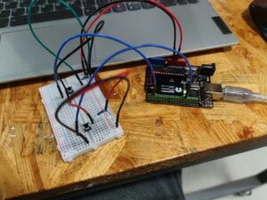
Something went wrong when I was building the circuit and the state of button didn’t change. I consult a IMA fellow and she changed the resistor’s position.
#include "SerialRecord.h"

// Change this number to send a different number of values
SerialRecord writer(2);
void setup() {
  Serial.begin(9600);
  pinMode(2,INPUT);
  pinMode(13,INPUT);
}

void loop() {
  int sensorValue1 = digitalRead(2);
  int sensorValue2=digitalRead(13);
  writer[0]=sensorValue1;
  writer[1] = sensorValue2;
  writer.send();

  // This delay slows down the loop, so that it runs less frequently. This can
  // make it easier to debug the sketch, because new values are printed at a
  // slower rate.
  delay(10);
}
In Arduino, I only use digitalRead to record the status of button and then send it to Processing.
import processing.video.*;
import processing.serial.*;
import osteele.processing.SerialRecord.*;
Serial serialPort;
SerialRecord serialRecord;
Movie myMovie;
int pvalue1;
int state1=1;
void setup() {
  size(600,600);
  myMovie = new Movie(this, "city.mp4");
  myMovie.loop();
  String serialPortName = SerialUtils.findArduinoPort();
  serialPort = new Serial(this, serialPortName, 9600);
  serialRecord = new SerialRecord(this, serialPort,2);
}

void draw() {
  serialRecord.read();
  int value1 = serialRecord.values[0];
  int value2 = serialRecord.values[1];
  println(value1,value2,state1);
  if (myMovie.available()) {
    myMovie.read();
  }
  if (value1 != pvalue1){

  if (value1==1 && state1%2==1){
    myMovie.pause();
    state1=state1+1;
  } else if (value1==1 && state1%2==0){
    myMovie.play();
    state1=state1+1;
  }
  }
  pvalue1=value1;
  if (value2==1){
    myMovie.speed(2.0);
  } else{
    myMovie.speed(1.0);
  }
  image(myMovie, 0, 0,width, height);
}
As for the Processing part, the main problem is that every time I press the button, the variable state1 will add up for multiple times, so I cannot pause the video when pressed only once and continue when pressed again. So professor suggested I define a new variable for keeping the previous state and change the if condition outside, so that it only increase when it is different from the previous state.
The trick I mentioned above is certainly useful, but I nearly forgot it until professor reminded me. There are many more tricks to make coding easier, and all of those come from making mistakes again and again.
IMA Recitation 9: Digital Fabrication
In recitation9, we want to make a kinetic sculpture that creates art using movement.
First, my partner and I had to make the base for our sculpture using cuttle.xyz. Since the base wasn’t to large, we changed the inches to milimeters. I first created a 80 mm wide and 120 mm tall rectange for the main body. Then, a 40 mm wide and 2.8 mm tall rectange, whose Y axis is -17.5 mm, on the side of the larger one. I used “Boolean Difference”, so that it looked as if it had been cut. Finally, according to the servo dimensions measured by my partner, a rectange was put on the center top. Two circles with the size of the servo’s screw hole were placed on both sides of it. Putting together the parts my partner built, the result looks like this.

After finishing the base, we only had to design the patterns that we want to put on the servo. A circle of 120mm was put on the canva’s origin point to make the designing easier. I first used pen to draw some lines and then use rotation repeat and outline stroke. A rectange was put in the center of my partner’s design, because it will need to integrate with the servo. A small circle representing the motor was in my design. We put together our design and it looked like this.
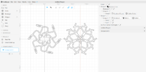
As for the laser cutting, we went to 823, where there were printing machine and all kinds of equipment. Some modifications were needed for my partner’s design, because it couldn’t hold the servo, so the professor there added a rectange inside as you can see from the picture.
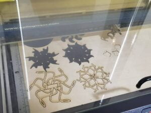
The final result looked like this after assembling together all the pieces.
IMA final project proposal
title: The Boundless Light

While I was thinking of the final project, a memory suddenly came into my mind. Several months earlier, I went to “teamLab Borderless Shanghai”, in which a mirror room with countless lights composing a boundless secene left a deep impression on me. I also reserch some of Yayoi Kusama’s works, who built the Infinity Mirror Room I mentioned before. Therefore, I decided to create something as imaginative as possible. Besides, “The Ascent” in my final project research post also give me insights on engaging the audience into a fanscinating experience. The challenge I will address is how to make neopixels display lights in different patterns according to the mouse position sent from Processing. This is intended to make the artifact more engaging and impressive, since the audience can see and play with it. I think this is pretty relavant to people who want to find insights for their artworks or want to broaden their imagination.
To build my project, I will first build up a wooden frame for the neopixels, only one side will be open to the audience, which ultimately makes a box with one door. Some reflective foil will needed to cover the inside of the box. With more reflection, the patterns will appear more dreamlike, which can help my intended audience. Second, I will integrate multiple neopixels into the box, which provides the main function of my project. Arduino is used in this step. Last is the programming. Since I want the audience to use the Processing to control the neopixels, I will have to record the mouse position and send it to Arduino. I plan to build the box next week. The neopixels may take much more time, but I will try to finish it also in the next week. The programming will happen simultaneously as I interagte the neopixels, so it won’t take many times. I suppose I can finish it in two weeks.
Back to the preparatory research, “The Ascent” gives me a visual shock, except for how it involves the audience. So does the Infinit Mirror Room. This is different from my midterm project which seems ordinary and boring at first glance. Light is a powerful way to attract people’s attention and leave impression on them. Thus, I was inspired and got the idea of the Boundless Light. This project is align with my definition of interaction, because it clearly leaves something in the audience’s heads. The message of immersing in this dreamlike experience is very obvious. I think this kind of interaction gives the audience an engagement what Ernest Edmonds concludes as “relating”. He describes it as “a long term interest, which occurs when the audience wants
to experience the work again and again, perhaps over many years” (12). Well, this is similar to what I have said in the begining, the experience of the room suddenly hopped into my mind. However, my project is different in that it let the audience control the lights and the patterns are varied.
My project leads to the interaction between human and lights. More creative artifacts can be built upon what I designed. Due to the restriction of space, I cannot make it a room for it, but I’m sure it will be amazing if the room displays different light patterns when people enters different sections. I hope many artists can be inspired just as what I have been, if so, this is the value of my project.