Taks1:

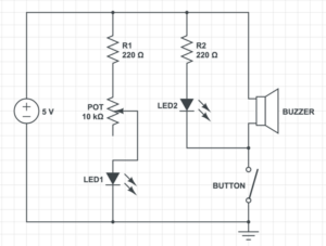
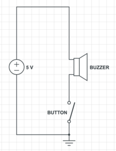
Above is the completion of the first task. I also add the schematics of it. As you can see the circuit contains two LED and one buzzer. The main purpose of button is to make the buzzer beep and LED2 goes off when pushed. On the route of LED1, the variable resistor can change the brightness of the light by altering the ohms. To build the circuit, my partner and I have to complete three steps, next I’ll explain what we have done, the problems encountered and how we solve it.
step1:
In step one, we need to make the buzzer beep when we push the button. But before we started, we took time to look at all the materials given to make sure the number is correct and to find the needed ones.

We soon build up the first edition of the circuit.

However, it was far from correct, because the buzzer wasn’t functioning. So we test whether the buzzer is damaged or not.

There is no problem with the buzzer, therefore it should be the button’s problem. We then consulted Proffessor Gottfield of how the button works. He demonstrated the working theory with the help of multimeter. As a result, two of the legs are permanently connected, while the other two are only connected when pressed. Connecting it properly, the buzzer could eventually make sound.
step2: 
Step2 requires us to add a LED into the circuit. At first, we thought it was a piece of cake, but the LED still wouldn’t work. My partener suggested we check the connection of the LEd. By using the multimeter, the connection problem could be excluded. We didn’t know what to do but to ask Professor Gottfield. Soon we found out that instead of giving us the 5 volt power supply, the power supply at hand was 12 volt. Obviously, the LEd couldn’t hold such high current. No wonder the buzzer make such a peculiar noise before.

We change the power and rebuild the circuit.
Seeing that the LED went off when pressing the button, we know step2 succeeded.
step3: 
Step3 was identical to step2, but differed in the variable resistor. We still encountered problem since we had no idea how the variable resistor works. Fortunately, with the experience from step2, we test the working theory of the resistor with the multimeter, discovering that it works very like the button. The problem was immediately solved.
As you can see, the brightness of the LED changed when we alter the ohms of the resistor.
task2:
Task2 required us to build a switch by using cardboard, copper tape, and wires. My partner and I had to build our own switch and then combine it together. In order to ensure good electric conduction, we peeled off the plastic outside the wire with pliers.

Taping it with copper tape, we entered the most important phase——soldering. We melted the a special metal that can conduct electricity (I forgot the name) with the electric iron. The electric iron is a special tool that can melt metals, but it has to heat up first so we should be especially careful with it. The soldering procedure not only stick the wire on the right place, but also ensure that it won’t easily drop.

Having build our own parts, we could finally replace the button with the switch after we tap the two parts. There’s one thing worth mentioning that is the length of the copper tape on the other side of the cardboard, which is the inside of the switch. In order to make the switch connected only when the two parts was touched, the length of the copper tape should be limited. I really admire such detailed thoughts, because it reminds me to think thoroughly before taking actions. While for the soldering, since I have had similar lessons in my high school, I didn’t feel much difficulties, but I was once burnt by the electric iron, so I always take it seriously. Though the experience was not completely different from my previous one at high school, the switch we built together was the proof for the interaction between my partner and I.
task3:
Compared to the former tasks, task3 appeared to be much easier, since you only need to replace the button with our hand-made switch.
In the recitation slide, there is a Mores code tablet, so my partner and I spent some time playing the circuit. I quickly learned how to type the “SOS” signal, while he tried to spell his name with it.
To sum up, the first recitation turned out to be an unforgettable experience. Unlike other recitations where you have to sit still and listen exhaustedly, the recitation of IMA surprised me with its interesting content and the process of thinking and building. This was one of the best recitation I’ve ever had.
Additional question:
1.What is the function of the resistor R1?
The purpose of the resistor is to protect the LED, limiting the current to below the maximum allowable current. We have experienced the use of resistor in step two, when the LED was burnt due to high current.
2.Looking at the following circuit, draw its diagram by yourself.

3.After reading The Art of Interactive Design, in what way do you think that the circuit you built today includes interactivity? Which degree of interactivity does it possess? Please explain your answer.
The circuit I built includes two kinds of interactivity. On one hand, the circuit respond with its LED on and buzzer beeps when I push the button, but such interactivity is of low quality. Such interaction with a emotionless circuit is no doubt less entertaining. On the other hand, there is interaction between my partner and I, which is apparently more fruitful. During the process of building the circuit, we frequently encountered problems that couldn’t be solved by one person, therefore, conversations happend very often during which one person gave a possible answer, the other one listened, thought carefully and respond whether its applicable or not, then we implement it. Nevertheless, both kind of interactivity is necessary.
4.How can Interaction Design and Physical Computing be used to create Interactive Art? You can reference Zack Lieberman’s video or any other artists that you know.
I think Interaction Design and Physical Computing can be used to creat Interactive Art in the way of capturing people’s body movement. Just as Zack Lieberman shown in his video, their team built a machine that captures your eye movement, which eventually proved helpful and enabled an old artist who was sick in bed draw again. I was deeply moved by what he said in the last minute, the old artist described the feeling as “take a breath after being held under water for 5 minutes”. Interaction is about allowing people to listen, think and speak (Crawford, C. 2002), which is exactly what the disabled can’t do. By capturing even the slightest movement of them and guess their real thoughts, we can create pragmatic Interactive Art.
reference: Crawford, C. Art of interactive design : A euphonious and illuminating guide to building successful software. January 1, 2002, pp.1-5http://s3-ap-southeast-1.amazonaws.com/ima-wp/wp-content/uploads/sites/3/2017/08/05164121/The-Art-of-Interactive-Design-brief.pdf