For the second recitation, we build a circuit and implement Arduino on it. The whole lesson includes three tasks or circuits. The first two tasks are individual ones and the third is group task.
circuit1:

Or as the real materials shows.

The circuit is rather simple, therefore I only need to implement the program on Arduino to let the light blink.

The codes are as follows.

The result was that the LED faded as expected. By changing the delay in the end I can alter the speed of fading, though I didn’t try.
circuit2:
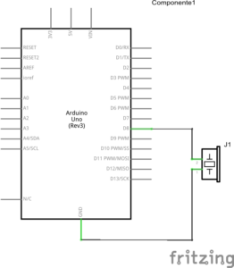
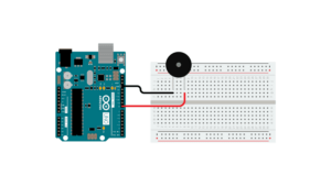
The second circuit was as simple as the first one since the connection was easy. I connected the buzzer to pin8 and ground. The purpose was to let the buzzer play a programmed melody.
circuit3:
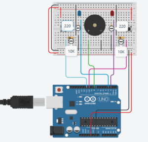
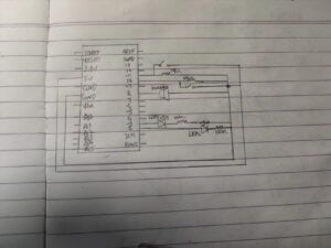
Considering the circuit was much complex than the former ones, I
carefully built it from left to the right. However, the problem was that the circuit couldn’t function. After finding out the wrong wire, the program could finally be implemented.
The purpose is to press the button as quickly as possible, the one who first reaches 10 times win the game as the light in front of him signals the winner, since it’s a two-player game.
In reflection, the experience of recitation was much more comfortable than recitation1. The proficiency and difficulties of the circuit might be the reason. But the last circuit was no doubt the most complex one and thus it took me a long time to debug. Just being careful is not enough, thoughtful consideration should be given both before and during building.
Question1:
The button I create is very much like a locker. Spining one turn equals to pressing the button once. Computer sees us through its input and output device (pp.xix), therefore, by changing the button to a more complex one, we can tell the computer that we are not merely species that only press the button. What’s more, pressing is a dull process, so I want to make it more flexible and interacive with the button spining.
Question2:
The resistor provides a connection to Ground, relevant when the button is not pressed. If we left out this connection, the input pin would sometimes not be connected to anything, whic is “floating”, and essentially act like an antenna. To ensure we always read LOW when the button is not pressed, we thus add a 10 kOhm resistor in a configuration known as a PULL-DOWN RESISTOR.
Question3:
The automatic bean sprouter on www.arduiro.cc is a compelling example for patching, since it only includes two interconnected parts, a sensor for humidity and temperature and a real-time clock that also activates water pump. The core of patching is to reduce the number of interruptions to the flow (pp.7). 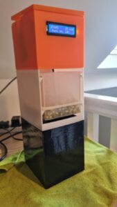
This simple yet pragmatic device caught my eyes the first time I saw it. As the creator describes, it can be done simply through 3D printers. I think the amazement was the reason why I chose it.