Documentation
Circuit 1: Fade
For week 2 recitation, we were tasked with building 3 different circuits based on the week’s lecture about Arduino. The first circuit was “fade” ; the schematics of it can be found below.
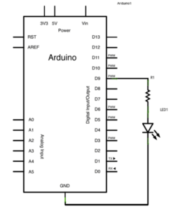
For the first step, I followed the schematic and used digital output 9 into the A12 slot in the breadbox. This serves as + power for the led. Then I plugged a 220r resistor into E12 , that went into 6D feeding into the positive leg of the led. Then I plugged ground into B5 therefore closing the circuit. After the circuit was completed, I went into Arduino IDE, and followed the prompt in the recitation instructions. After uploading the code, the led started blinking in a fade motion. One problem that I encountered at the beginning of this circuit was that the Software did not recognize the microcontroller, so I had to manually set it up within IDE.
Video circuit 1:
Circuit 2: Tone/Melody
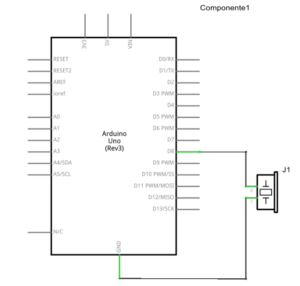
Circuit 2 was simpler than circuit 1, it did not require a resistor and it was just a direct connection between the buzzer/microcontroller. I followed the schematic, but encountered problems on the software side. I learned that every time you open a new file in Arduino, you have to manually select the board again.

Circuit 2 video:
Circuit 3: Speed game
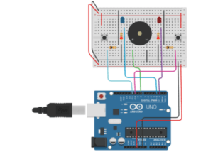
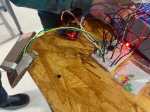
This circuit was the most time consuming to build. The first step I took was to wire the cables in the microcontroller. Then I built the circuit from top left to bottom left, and then move right wise. This technique ensures order, and also that cables are plugged in where they are supposed. After finishing the circuit, I got the code from Tinkercad, and pasted it into the Arduino interface, at first nothing happened, and I checked if the upload port was selected correctly, and I had to manually select it. After uploading the code successfully I tried clicking one of the buttons for 10 times, and the led lit up, along with a victory tune. After I tried competing with my neighbor, we also tried switching to the switch we soldered last week.
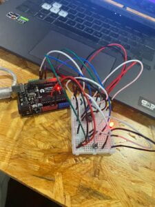
Speed game with soldered switches:
Video C3 test:
C3 competition:
C3 soldered switch competition:
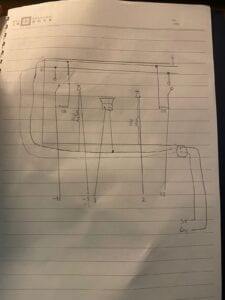
your own drawing of the schematic for circuit 3!
Question 1: Propose another kind of creative button you could use in Circuit 3 to make the game more interactive. Read and use some material from the Physical Computing, Introduction Chapter (p. xvii – p. xxix) to explain why this button would make this game more interactive.
I would propose a pressure activated that would be placed on the floor, as the book states “you will want the user to throw a switch without knowing it” (Sullivan/Igoe 89) placing the button on the floor and getting someone to stomp on it as fast as possible will result more natural, and interactive, as they will have to move their whole bodies.
Question 2: Why did we use a 10 kOhm resistor with each push button? (Psssst… Go back to your slides for this answer)
Because it will connect to ground when the switch is open, and there is no voltage coming through. It is basically a way for the microcontroller to determine if the switch is being pressed or not.
Question 3: In the book Getting Started with Arduino there is a clear description about the “Arduino Way” in chapter 2. Find a project that you find interesting that can be used as an example for these kinds of projects. Cite it in an adequate manner, include a picture, and explain the reasons that you chose it.
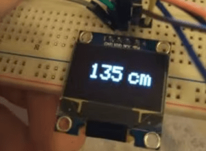
I found this project interesting, because it provides real time feedback on distance relative to the sensor. This would allow for a very intuitive way to measure the distance between objects, and accurately, because of the ultrasonic sensor. I chose it, because it could help with providing measurements for future projects, and could also be used for future projects, as a proximity sensor.
references:
Arduino distance sensor and OLED. (2021, 2). Retrieved from https://www.hackster.io/rayan-kiwan/arduino-distance-sensor-and-oled-0ff5f7
Leave a Reply