Documentation:
For your documentation, create a blog post that includes the following items based on your experience in this recitation. Include all of these elements in your documentation:
For each of the three steps in Task 1:
Write what the circuit does, and some observations on how the components accomplish this.
This circuit connected a buzzer to a button. It used a 5v power source for power. Once you pressed the button, it closed the circuit and made the buzzer go off. Include pictures and or videos of the completed circuit working.
For the first circuit, my partner Tawan, and I sorted all the components. It is important to stay organized throughout the whole process. As it was my first time working with a breadbox, my partner explained to me some basic stuff, and we started wiring everything together. The circuit only activates after the button is pressed as this closes the circuit.
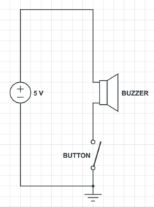
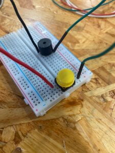
First Circuit Video:
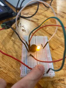
For the second circuit, we added an led and a resistor into the circuit. This was done in order to add a visual cue. Once we tried pressing the button to close the circuit, the buzzer went off, but the led did not light up. Upon closer checking we realized that we plugged the power cable that fed the led one hole below, so we plugged it back correctly, and it worked!
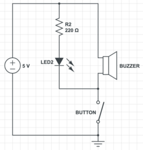
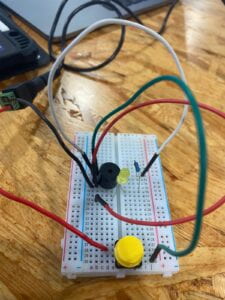
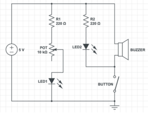
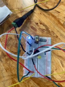
On circuit 3, a potentiometer, and a new LED were added, the potentiometer is used for regulating the amount of power delivered, thus serving as a dimmer, and with the new LED added, it serves as confirmation of power within the circuit. We also decided to replace the physical button, for the one we soldered.
For Task 2: Switch building
- Describe your process in task 2, highlighting things you learned, any difficulties you had, any comments about what you made and how you made it. Include a photo.
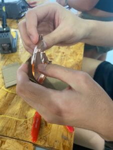
- For the soldered button we started with 2 pieces of cardboard, and copper tape. We folded half the length of the copper tape towards the other to make a contact area, then we tape the cable in, soldered it, and repeated the same step for the other piece of cardboard.
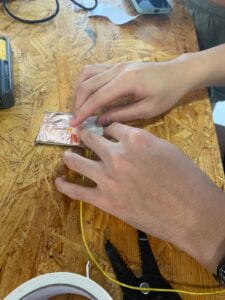
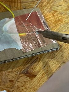
For Task 3:
- Describe what you did in task 3, and how you worked with your partner. Include relevant photos or videos.
- We paired up with a neighboring group, and Tawan and I decided on the word “hello.” It took the other group quite some time to decode, but in the end they did it. We couldn’t decode their words, because the recitation was over.
Additional Required Questions: Take time to reflect on this week’s readings and the recitation exercise to answer these questions:
- Question 1: What is the function of the resistor R1? (You can read about the reason why LEDs need resistors here)
- The function of the resistor is to keep the power provided to a component below its threshold, thus keeping it from damaging itself.
- Question 2: Looking at the following circuit, draw its diagram by yourself.
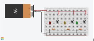
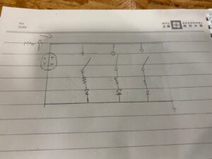
- Question 3: After reading The Art of Interactive Design, in what way do you think that the circuit you built today includes interactivity? Which degree of interactivity does it possess? Please explain your answer.
-
- I think that the circuit built includes interactivity because it beeps every time you press the button. It possesses a low level of interactivity, because it requires human input in order to function, and it is only wired to do a certain action.
- Question 4: How can Interaction Design and Physical Computing be used to create Interactive Art? You can reference Zack Lieberman’s video or any other artists that you know.
- There are lots of possibilities when we talk about merging interactive design, and computing. One of such examples is how Zach Lieberman used his knowledge of both fields in order to give a canvas to a paralyzed person a chance to do graffiti after a long time of not being able to because of mobility issues. This goes on to prove the huge potential that combining both disciplines could have in the real world.
Leave a Reply