“The Box of Illusions” by Kelvin & Bruce
Introduction
“The Box of Illusion” is an interactive art project that combines elements of music, light, infrastructure, and user interaction to create a dynamic visual experience. Inspired by popular light-shadow art exhibitions and the interactive game “Monument Valley,” this project aims to explore the interaction between visuals, sounds, and user engagement. By incorporating Processing and Arduino codes, this interactive installation allows users to manipulate the arrangement of the objects placed in the spinning platform and the speed of the spinning plate form according to the distance between the user and the box. Besides, the background music will change in response to the distance change, creating unique atmospheres. This blog post will outline the detailed procedure of building the project, from conceptualization to material selection and technical implementation.

Conceptualization and Initial Design
To begin the project, My teammate and I drew a draft on a whiteboard to outline the main components of the installation to demonstrate the basic components that consist of the project.
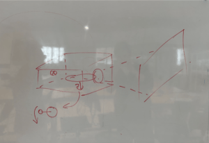
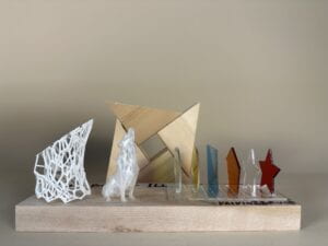
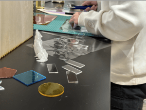
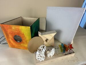
The two primary parts are the “projector” and the canvas. The projector serves as a concealed black box containing light sources and a spinning platform. Users can place objects on the spinning platform. The light from the light sources attached to the side of the box will go through the colorful transparent and 3D-printed objects, which creates dynamic visual effects on the canvas. 3mm acrylic boards are used to craft colorful transparent objects placed on the spinning platform. We initially design some different geometric shapes, such as stars, pentagons, circles, etc. Then, we used the laser cut machine to cut these shapes on the acrylic board. To make them look colorful. We applied the colorful films to the acrylic. Besides, we also carved bases for each shape, which allows them to “stand” on the spinning platform. In addition to the colorful transparent acrylic objects, we planned to 3D print an object to create a shadow effect. At first, we printed a little “wolf”, but the relatively dense structure makes the light hard to go through. Hence, we chose a porous object that looks like a trunk. The light can go through the holes in the object to create a fabulous light and shadow image. Besides, right opposite the light source, there’s a convex lens to amplify the image on the canvas. The focal length of the convex lens is 7 cm. According to the convex lens imaging principle, when parallel rays of light pass through a convex lens the refracted rays converge at one point called the principal focus. Therefore, the canvas should be placed beyond the focal length to create an amplified image. We finalize the size of our box (or projector) as 23*30*23 cm.
Building Process
Light Sources and Projection
We’ve done previous research to find high-power light sources that are capable of projecting enough bright light through the objects, the convex lens, and finally onto the canvas. We have to ensure that the chosen light source has the necessary intensity and color range to achieve the desired visual effects. To reach the goal, we chose a 12V spotlight, which is bright and concentrating enough to project the light to the canvas.
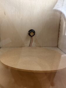
We use two snails to fix the light to the box, and the position of the light corresponds to the position of the convex lens to ensure that the light can go through the lens vertically. After fixing the light and the convex lens, we experimented with the distance between the projector and the canvas, which helps us to finalize the size of the canvas and the distance maintained between the canvas and the projector.
Spinning Platform and User Interaction
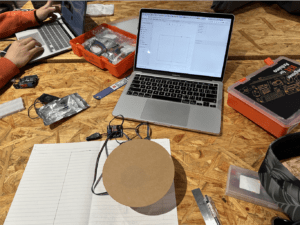
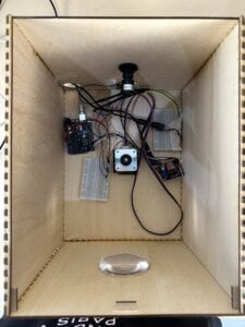
The spinning platform is motivated by a stepper motor, allowing users to control its speed of rotation by receiving the data from the ultrasonic sensor. We focus on creating a responsive and precise mechanism to ensure an engaging user experience. Therefore, we experimented with the accuracy of the ultrasonic sensor and the response of the stepper motor. During this experiment process, we found a problem concerning the inconsistency between the data from the sensor and the stepper motor. Since the data from the ultrasonic sensor keeps changing, the speed of the motor changes correspondingly. However, the frequently changing data makes the change of speed a little “laggy”. To solve this issue, we consulted the LA Kevin, he suggested we use the updated data less frequently. Hence, we made some adjustments to the code to let the sensor send data to the motor less frequently, which indeed made the spinning smoother. As for the structure of the spinning board, we used the 3D-printed “adaptor” that we used in the recitation as the joint between the motor and the platform. The platform is also created with a 3mm acrylic board whose radius is 7 cm. We used the hot glue gun to glue the platform to the “adaptor” . we have to ensure that the platform is stable, rotates smoothly, and can support the weight of the objects placed on it.
Serial Communication
Taking inspiration from the game “Monument Valley,” we decided to incorporate sound into the installation. Arduino and Processing are used to establish serial communication between the physical installation and the sound system. Two mp3 files are uploaded to the processing program. The sound is also controlled by the ultrasonic sensor. As mentioned above, the ultrasonic sensor controls the speed of the stepper motor — When the user moves closer to the box, the speed will decrease, and vice versa. Correspondingly, the first music will play of the distance between the user and the box is larger than 30 cm, and vice versa. To reach this goal, we have to collaborate the Arduino and processing code by the serial communication function. This integration of sounds and visuals enhances the immersive experience and provides auditory feedback to the user’s actions. We also did several tests to the sound integration to ensure proper synchronization between visuals and audio.
Material Selection and Construction
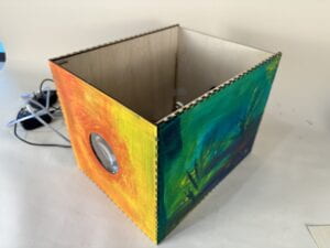
Based on the initial design, we proceeds to select materials for the construction of the installation. Transparent and colorful materials, such as acrylic with attached films are chosen for the objects placed on the spinning platform. Laser cutting is employed to cut the materials into the desired geometric shapes while 3D-printing technology is used to create intricate and detailed objects. The sides of the box are cut using the laser cutting machine and then assembled together to form the concealed black box structure. Attention is given to precision and aesthetics during the assembly process to ensure a visually appealing installation.
Testing and Refinement
Once the construction is complete, we and other people tested the installation to ensure all components are functioning correctly. This phase involves thorough testing of the spinning platform, light projection, sound integration, and user interaction. We verified the smooth rotation of the spinning platform, ensuring that it responds accurately to the user’s input through the ultrasonic sensor. We also verified that the light sources project vibrant and well-defined visuals onto the canvas. Additionally, we conducted tests to ensure that the sound system responds appropriately to user interaction, playing the correct audio files in synchronization with the visual changes. During the user testing phase, any issues or areas for improvement are identified and addressed promptly. This may involve fine-tuning the stepper motor to enhance the precision of the spinning platform or adjusting the positioning of the light sources to optimize the projection quality. We also paid attention to the durability and stability of the installation, ensuring that all components are securely fastened and capable of withstanding repeated use.
With “The Box of Illusion” installation complete and thoroughly tested, users are invited to explore and interact with the dynamic visuals and sounds created by the interplay of lights, shadows, and user input. The installation offers numerous visual possibilities influenced by variables such as the angle of the spinning platform, the variety of geometric shapes, and the colors chosen for the objects. Users are encouraged to engage with the project, immersing themselves in the captivating experience and discovering the unique visual landscapes they can create.
Conclusion
“The Box of Illusion” is an interactive art installation that combines music, light, and user engagement to create a captivating visual experience. From the initial conceptualization and design phase to the selection of materials, construction, and technical implementation, the project involves careful consideration of each component to ensure a seamless and immersive user experience. By integrating sound and utilizing technologies such as Processing and Arduino, the installation offers an interactive and dynamic platform for users to explore and enjoy the interplay between visuals and sounds. “The Box of Illusion” invites users to engage with the project, creating their own visual narratives and experiencing the magic of light and shadow in an interactive and artistic manner.
Appendix
Processing
//
import processing.serial.*;
Serial serialPort;
int NUM_OF_VALUES_FROM_ARDUINO = 1;  /* CHANGE THIS ACCORDING TO YOUR PROJECT */
/* This array stores values from Arduino */
int arduino_values[] = new int[NUM_OF_VALUES_FROM_ARDUINO];

import ddf.minim.*;

Serial myPort;
Minim minim;
AudioPlayer music1, music2;

void setup() {
  size(400, 400);
  background(255);

  printArray(Serial.list());
  // Open the serial port and set the baud rate to match the Arduino sketch
  serialPort  = new Serial(this, "/dev/cu.usbmodem1101", 9600);

  // Load the music tracks
  minim = new Minim(this);
  music1 = minim.loadFile("music1.mp3");
  music2 = minim.loadFile("music2.mp3");
}

void draw() {
  background(255);
  // receive the values from Arduino
  getSerialData();
  println(arduino_values[0]);
  float distance = arduino_values[0];

  //if (serialPort.available() > 0) {
  //  String distanceString = myPort.readStringUntil('\n');
  //  if (distanceString != null) {
  //    int distance = int(distanceString.trim());

  if (distance > 30) {
    if (!music1.isPlaying()) {
      music1.play();
    }
    if (music2.isPlaying()) {
      music2.pause(); // pause music2 if it is already playing
    }
  } else {
    if (!music2.isPlaying()) {
      music2.play();
    }
    if (music1.isPlaying()) {
      music1.pause(); // pause music1 if it is already playing
    }
  }
}
//}
//}

void getSerialData() {
  while (serialPort.available() > 0) {
    String in = serialPort.readStringUntil( 10 );  // 10 = '\n'  Linefeed in ASCII
    if (in != null) {
      print("From Arduino: " + in);
      String[] serialInArray = split(trim(in), ",");
      if (serialInArray.length == NUM_OF_VALUES_FROM_ARDUINO) {
        for (int i=0; i<serialInArray.length; i++) {
          arduino_values[i] = int(serialInArray[i]);
        }
      }
    }
  }
}
Arduino
#include


int DIR_PIN = 2;
int STEP_PIN = 3;
int EN_PIN = 4;
int counter = 0;
int lastD;
// Define a stepper and the pins it will use
// AccelStepper::DRIVER means a stepper driver (with step and direction pins)
AccelStepper stepper(AccelStepper::DRIVER, STEP_PIN, DIR_PIN);


// defines ultrasonic pins numbers
const int trigPin = 6;
const int echoPin = 5;
// defines variables
long duration;
int distance;


void setup() {
  //Ultrasonic Input&Output
  pinMode(trigPin, OUTPUT);  // Sets the trigPin as an Output
  pinMode(echoPin, INPUT);   // Sets the echoPin as an Input
  Serial.begin(9600);
  // Enable the stepper driver by setting the
  // EN pin to LOW
  pinMode(EN_PIN, OUTPUT);
  digitalWrite(EN_PIN, LOW);
  // The run() function will accelerate up to
  // the speed set here
  stepper.setMaxSpeed(2000);
  // Set the desired constant speed for use with
  // runSpeed()
  stepper.setSpeed(200);
}


void loop() {


  digitalWrite(trigPin, LOW);
  delayMicroseconds(2);
  // Sets the trigPin on HIGH state for 10 micro seconds
  digitalWrite(trigPin, HIGH);
  delayMicroseconds(10);
  digitalWrite(trigPin, LOW);
  // Reads the echoPin, returns the sound wave travel time in microseconds
  duration = pulseIn(echoPin, HIGH);
  // Calculating the distance
  distance = duration * 0.034 / 2;
  // Prints the distance on the Serial Monitor
  // Serial.println(distance);  // Send the distance to the serial port


  Serial.println(distance);


  if (counter % 10 == 0) {
    // Clears the trigPin


    if (abs(lastD - distance) > 0) {
      int speed = constrain(map(distance, 0, 55, 2000, 200), 200, 2000);


      // Set the stepper motor speed
      stepper.setSpeed(speed);


      // Move the stepper motor at the set speed
    }


    lastD = distance;
  }
  stepper.runSpeed();
  counter++;
}