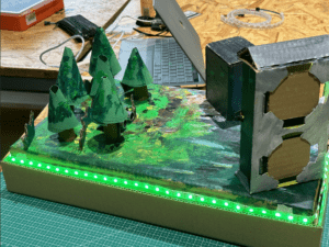
“Green Distance” Blog — Kelvin & Bruce Instructed by Professor Margret
Part 1: Research & Scratch
Before starting to create the project, I’ve researched several interactive projects that triggered me to think about the definition of “interaction”, contributing to forming the concept of our project. The project I initially researched is “Robotic Voice Activated Word Kicking Machine” created by Neil Mendoza.
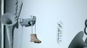
This project triggered me to consider how to allow users to interact with our project involving multiple senses. In Neil’s project, he visualizes the verbal words, and users can also hear the words that fall into the “speaker”. The combination of senses makes users can immersively interact with this art installation. Hence, during the planning stage of our project, I try to integrate different senses into the project, interacting with users in multiple ways. According to that inspiration, I plan to use lights and sounds to interact with users.
The second interactive art project I researched provided me with inspiration for the theme of our midterm project. The project I found is a VR installation project created by artists Lily and Honglei. They integrate the Chinese traditional art form – shadow play with newly-emerging VR technology. They focus both on the cultural and environmental destruction triggered by rapid urbanization and industrialization. This project provides me with inspiration on the topic of the “distance” between human intervention and nature. In other words, through my projects, I hope to find a “perfect” distance between culture and nature.
Hence, based on the previous thought on the integration of senses and the theme, I drew a scratch of the project. This project is composed of two main parts – “urbanization” and “nature” divided by an “alert line”. In the “urbanization” part, the player can put the “modern buildings” on that part. The “nature” part, it will include a distance sensor, a buzzer, and several green and red LED lights. The distance sensor will “draw” the “alert line” between two different parts. If the distance between the “buildings” put by the player and the “nature” part is less than the pre-programmed distance, the LED lights attached to trees will turn from green to red and the buzzer will make a siren sound. Through interacting with this project, I hope people can reflect on the consequences brought around by rapid urbanization, suggesting a novel way to interact with nature and remain a “green distance” between humans and nature.
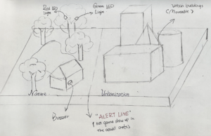
Fig. 2 Initial scratch of the “Green Distance” projectPart 2: Crafting & Coding
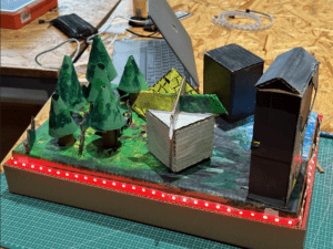
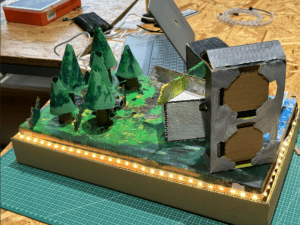
After setting the draft of our project, we began to build the project. We basically divided our making process into two main sections — cardboard crafting and coding. We chose cardboard as our material initially for the project because of its high accessibility. Additionally, cardboards are easy to be crafted with knives and scissors compared to other materials like plastics. Cardboards are also relatively eco-friendly because they are recyclable. There are three main parts we have to make out of cardboard — the base, trees, and buildings. We chose the thick cardboard for the base to enhance its stability. For the trees, we used scrolled cardboard to make trunks and thin green cardboard for the leaves. We also made different types of buildings out of cardboard, such as tall cuboid residential buildings and a pyramid.
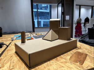
After finishing the cardboard-making process, we planned to color it to make it look better and more intuitive. Bruce was in charge of painting the base into a “grassland”. I pained the buildings in different colors.
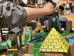
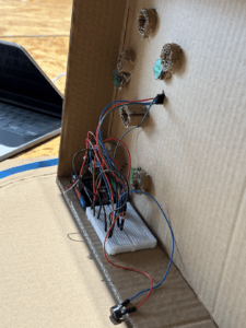
During the crafting process, everything went pretty smoothly. We had a clear division of work, increasing the efficiency of our crafting process. However, we encountered an issue with how to fix the trees on the cardboard. We first directly stuck the trees on the base by applying a glue gun, but the trees easily fell down. Hence, instead of “sticking” the trees onto the board, I dug holes in the base according to the size of the tree and stuffed trees in them, which increased the stability of the trees and made it convenient for us to put electronic components from below.
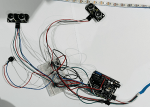
After the crafting process, we began to work on the Arduino. According to our initial scratch, we need several LED lights, a buzzer, an ultrasonic sensor, and several cables. Here is our initial code:
int buzzer = 3, ledRed = 6, ledYellow = 9, ledGreen = 10;int triggerPin = 4;int echoPin = 2;long readTime(int triggerPin, int echoPin) {// In order for the sensor to send out a pulse the trigger needs to be set low for 2us// Then set HIGH for 10uspinMode(triggerPin, OUTPUT);digitalWrite(triggerPin, LOW);delayMicroseconds(2);digitalWrite(triggerPin, HIGH);delayMicroseconds(10);digitalWrite(triggerPin, LOW);pinMode(echoPin, INPUT);returnpulseIn(echoPin, HIGH);}void setup() {Serial.begin(9600);pinMode(buzzer, OUTPUT);pinMode(ledRed, OUTPUT);pinMode(ledYellow, OUTPUT);pinMode(ledGreen, OUTPUT);}void loop() {int distance;distance = 0.01715 * readTime(triggerPin, echoPin); // From calculation above Distance = 0.0343 / 2 * readTimeSerial.print("distance: ");Serial.print(distance);Serial.println("cm");if(distance < 10){digitalWrite(ledRed, HIGH);digitalWrite(buzzer, HIGH);delay(500);digitalWrite(buzzer, LOW);delay(500);}if(distance >= 10 && distance <= 30){digitalWrite(ledYellow, HIGH);digitalWrite(ledRed, LOW);digitalWrite(ledGreen, LOW);}if(distance > 30){digitalWrite(ledGreen, HIGH);digitalWrite(ledRed, LOW);digitalWrite(ledYellow, LOW);}}
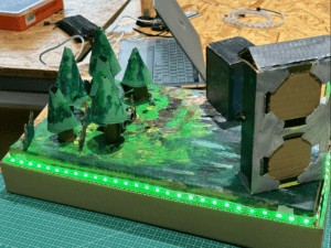
// Define the pins for the componentsint buzzer = 3;// int ledRed = 6;// int ledYellow = 9;// int ledGreen = 10;int triggerPin = 4;int echoPin = 2;int triggerpin = 9;int echopin = 8;// Include the NeoPixel library#include <Adafruit_NeoPixel.h>// Define the NeoPixel parameters#define LED_PIN 12#define LED_COUNT 60// Create a NeoPixel objectAdafruit_NeoPixel pixels(LED_COUNT, LED_PIN, NEO_GRB + NEO_KHZ800);// Function to calculate the distance using the ultrasonic sensorlong readTime(int triggerPin, int echoPin) {pinMode(triggerPin, OUTPUT);digitalWrite(triggerPin, LOW);delayMicroseconds(2);digitalWrite(triggerPin, HIGH);delayMicroseconds(10);digitalWrite(triggerPin, LOW);pinMode(echoPin, INPUT);returnpulseIn(echoPin, HIGH);}void setup() {// Start the serial communicationSerial.begin(9600);// Initialize the NeoPixel objectpixels.begin();// Set the pin modes for the componentspinMode(buzzer, OUTPUT);// pinMode(ledRed, OUTPUT);// pinMode(ledYellow, OUTPUT);// pinMode(ledGreen, OUTPUT);}void loop() {// Calculate the distance using the ultrasonic sensorint distance1 = 0.01715 * readTime(triggerPin, echoPin);int distance2 = 0.01715 * readTime(triggerpin, echopin);// Print the distance to the serial monitorSerial.print("Distance1: ");Serial.print(distance1);Serial.println(" cm");Serial.print("Distance2: ");Serial.print(distance2);Serial.println(" cm");// Set the colors of the NeoPixel based on the distanceif(distance1 < 12.5 || distance2 < 12.5){pixels.fill(pixels.Color(255, 0, 0), 0, 60); // Red colorpixels.show();tone(buzzer, 440, 500);delay(200);noTone(buzzer);tone(buzzer, 330, 500);delay(200);noTone(buzzer);tone(buzzer, 220, 500);delay(200);noTone(buzzer);delay(500);// digitalWrite(ledRed, HIGH);// digitalWrite(ledYellow, LOW);// digitalWrite(ledGreen, LOW);}elseif((distance1 >= 12.5 && distance1 <= 20) || (distance2 >= 12.5 && distance2 <= 20)){pixels.fill(pixels.Color(255, 255, 0), 0, 60); // Yellow colorpixels.show();// digitalWrite(ledYellow, HIGH);// digitalWrite(ledRed, LOW);// digitalWrite(ledGreen, LOW);}else{pixels.fill(pixels.Color(0, 255, 0), 0, 60); // Green colorpixels.show();// digitalWrite(ledGreen, HIGH);// digitalWrite(ledRed, LOW);// digitalWrite(ledYellow, LOW);}}
Part 3: Conclusion
