Geo-Dash:Jump – Keigan Carpenter- Professor Rodolfo Cossovich
A. CONCEPTION AND DESIGN:
In our initial stages, we started with 3 preliminary ideas:
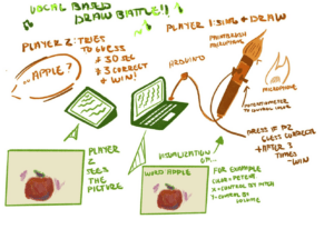
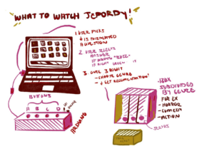
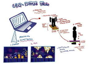
We ended up going with our last idea of re-creating “Geometry Dash” with an interactive component. “Geometry Dash” is a popular mobile game where players would usually tap on the phone screen which would cause the square character to jump (to avoid obstacles and progress through the levels). Another function was a rocket where players would hold the screen to make the rocket move up and release the screen to make the rocket drop. I have attached a screenshot from the game for reference.

The initial idea for the interactive component was that the players could make the square jump by physically jumping and activating a sensor. We had the idea of a hula-hoop object that would act as a “physical rocket” for the rocket function. Moving this up and down (a distance sensor is recording that) would correspond to moving the rocket up and down. Overall, the goal was to re-imagine this classic/nostalgic game into something interactive. The functions paired with the visualizations/music were planned to be enjoyed by a diverse audience.
In the design process, we decided to narrow the physical functions down to the jump function only. After talking to Professor Rudi about the idea, we thought it would be too complicated for the user to switch positions, so we focused on this user-specific task and complicated it further within the code. After we decided on the design and got the green light, we started prototyping.
B. FABRICATION AND PRODUCTION:
First, to begin prototyping I focused on wiring a button and running Arduino code to ensure the Arduino was reading values sent by the button. During this time Shauna was working on a process sketch that was supposed to be a square, essentially, that would react to the button and make it jump.
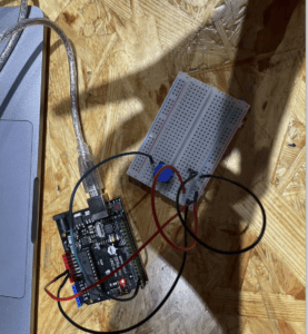
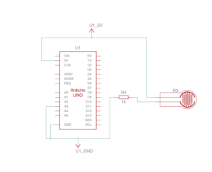
After completing aspects of the processing code (via adapting codes from various sources and help from the instructors, Fellows, and LAs :), we had our prototype. Without changing the wiring (The Tinkercad is in the appendix) I switched out the button for a vibration sensor. I placed the sensor between a piece of cardboard and 3mm wood. This initial test was successful (in the sense that the square was reacting to the sensor).
At this stage, the main struggle was getting the integration between Arduino to Processing to run more smoothly. Also since we did not have much coding experience before this class, there was a large learning curve in terms of the processing code.
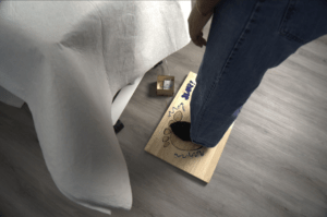
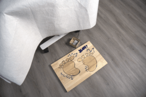
While we continued developing the processing sketch, I began to laser-cut/engrave the jump pad users would stand on when playing the game. This part was very smooth. I engraved footprints on a 3mm piece of wood that I attached to a piece of cardboard. I placed the sensor in between the cardboard and the wood.
At this point, we also decided that instead of the square moving to avoid the object, the square would stay still and the object would be to avoid some objects.
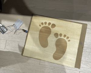
The video below shows me testing the project the day before user testing. The main criticisms we received during user testing were regarding the processing sketch. For example, the sporadic directionality of the squares was a big concern considering the array we used created so many squares that it was impossible to avoid gaining points. There were other points about the circle and the logic of the point system.
In terms of the physical interaction, many people commented that getting to jump was entertaining however they said the game was too difficult. Also, the jump had a massive delay and you did not have to use both feet to jump on the pad. Since the sensor was situated on one side, it ended up working more smoothly when users would use one foot to stomp rather than jump.
While Shauna worked on fixing the processing code, I worked on fixing the sensor issue. To make sure that the user had to use both feet and jump to activate the sensor, we switched sensors from the vibration sensor to the force sensor.
However, since the force sensor was extremely sensitive we ended up making an entirely new board. This board was thicker and the sensor was attached to the bottom via the previous board. However, there was a lot of trial and error here to make sure that the sensor was working accordingly. Once we adjusted the code to the force sensor (going from digital to analog, so having to read a range of values instead of on), that was all we had left on the physical interaction side.
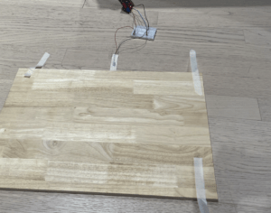
Afterward, I laser-cut a box to put the breadboard/Arduino in. Also, I assembled the sensor underneath the new pad I was able to use markers and design the board with cartoonish/graffiti-type style illustrations.
At this point, I also re-drew the background of the visualization and added the rest of the music.
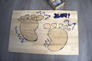
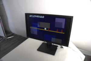
Here is a video of me testing the game before the final presentation after we added and refined the processing code and music. The only thing missing at this point was adding the “floor” for the square. Another point is we ended up changing the directionality of the objects, turning them into red triangles to signal danger, and reversing the points system (so you lose points when you hit the triangles).
This is a screen recording of what is being displayed on the monitor. At this point, we had not changed the code range for detecting the object, so the player could not move and not lose points.
Here are the codes that we used for the project:
Arduino code:
void setup() {
  Serial.begin(9600);
}

void loop() {
  // to send values to Processing assign the values you want to send
  // this is an example:
  int sensor0 = digitalRead(A3);


  // send the values keeping this format
  Serial.print(sensor0);
  Serial.println("");  // put comma between sensor values


  // too fast communication might cause some latency in Processing
  // this delay resolves the issue
  delay(20);

  // end of example sending values
}
- Processing Code for the visualization:
// global variables (top of sketch)
float[] xs = new float[10];
float[] ys = new float[10];
float[] sizes = new float[10];
color[] colors = new color[10];
float[] xspeeds = new float[10];
float[] yspeeds = new float[10];

player p1;
int obstacles;
PImage img;
PFont FONT;

import processing.serial.*;
import processing.sound.*;

//declare a SoundFile object
SoundFile sound;
SoundFile sound2;

Serial serialPort;
int NUM_OF_VALUES_FROM_ARDUINO = 1;  /* CHANGE THIS ACCORDING TO YOUR PROJECT */
/* This array stores values from Arduino */
int arduino_values[] = new int[NUM_OF_VALUES_FROM_ARDUINO];

void setup() {
  fullScreen();
  //size(800, 400); this was used to check the gameplay without having it run full screen so we could still see the processing values
  p1 = new player (width/2, height/2, 100, 100);

  sound = new SoundFile(this, "baseafterbase.mp3");
  // play the sound on loop
  sound.loop();

  sound2 = new SoundFile(this, "lost.mp3");


  img=loadImage("FinBackresize.jpg");


  FONT = createFont("GameFont.ttf", 100);

  printArray(Serial.list());
  // put the name of the serial port your Arduino is connected
  // to in the line below - this should be the same as you're
  // using in the "Port" menu in the Arduino IDE
  serialPort = new Serial(this, "COM10", 9600);

  for (int i=0; i < 3; i=i+1) {
    xs[i] = random(width);
    //ys[i] = random(height);
    ys[i] = random(600, 650);
    sizes[i] = random(50, 100);
    colors[i] = color(255, 0, 0);
    xspeeds[i] = (9);
    //yspeeds[i] = random(1, 5);
  }
}

void draw() {
  // receive the values from Arduino
  getSerialData();

  // use the values like this:
  float x = map(arduino_values[0], 0, 1023, 0, width);
  float y = map(arduino_values[0], 0, 1023, 0, height);


  if (arduino_values[0] == 1) {
    p1.isJumping = true;
  }


  // the helper function below receives the values from Arduino
  // in the "arduino_values" array from a connected Arduino
  // running the "serial_AtoP_arduino" sketch
  // (You won't need to change this code.)

  image(img, 0, 0);

  //background (42);


  noStroke();
  for (int i=0; i < 3; i=i+1) {
    fill(colors[i]);
    //circle(xs[i], ys[i], sizes[i]);
    triangle(xs[i], ys[i], (xs[i]-50), (ys[i] +200), (xs[i] + 50), (ys[i] + 200));
    xs[i] = xs[i] - xspeeds[i];
    //ys[i] = ys[i] + yspeeds[i];
    //println("ys[i] " + ys[i]);
    // check right edge
    if (xs[i] < 0) {
      xs[i] = width;
    }
    // check bottom edge
    if (ys[i] > height) {
      ys[i] = 0;
    }

    fill (255);
    /*this part of the code was adapted from Chris Whitmire Lessons. Getting a Player to Move Left and Right in Processing. 2022. YouTube, https://www.youtube.com/watch?v=jgr31WIYWdk.
     and Chris Whitmire Lessons. Getting a Player to Jump in Processing. 2022. YouTube, https://www.youtube.com/watch?v=8uCXGcWK4BA.
     */

    p1.render();
    p1.jumping();
    p1.falling();
    p1.JumpStop();
    p1.land();

    // when player comes into constact with an obstacle
    if (dist(p1.x, p1.y, xs[i], ys[i]) < sizes[i]) {
      println("hit by " + i);
      obstacles -=1;
      println(obstacles);
    }
    textSize(100);
    fill(255);
    textFont(FONT);
    text("score" + (obstacles+100), 20, 120);
  }
  if (obstacles <= -100) {
    for (int i=0; i < 3; i=i+1) {
      xs[i] = 0;
      tint(255, 0, 0);
      sound.amp(0);
      sound2.play();
      //image(img, 0, 0);
      textSize(100);
      fill(255);
      textFont(FONT);
      text("GAME OVER", 560, 370);
    }
  }
}


void getSerialData() {
  while (serialPort.available() > 0) {
    String in = serialPort.readStringUntil( 10 );  // 10 = '\n'  Linefeed in ASCII
    if (in != null) {
      //print("From Arduino: " + in);
      String[] serialInArray = split(trim(in), ",");
      if (serialInArray.length == NUM_OF_VALUES_FROM_ARDUINO) {
        for (int i=0; i<serialInArray.length; i++) {
          arduino_values[i] = int(serialInArray[i]);
        }
      }
    }
  }
}
- This is the Processing code for the player
class player {
  /*this part of the code was adapted from Chris Whitmire Lessons. Getting a Player to Move Left and Right in Processing. 2022. YouTube, https://www.youtube.com/watch?v=jgr31WIYWdk.
   and Chris Whitmire Lessons. Getting a Player to Jump in Processing. 2022. YouTube, https://www.youtube.com/watch?v=8uCXGcWK4BA.
   */
  int x;
  int y;

  int w;
  int h;

  boolean isMovingLeft;
  boolean isMovingRight;

  boolean isJumping;
  boolean isFalling;

  int speed;

  int jumpHeight; //distance you can jump up
  int topOfJump; //y value of top of jump

  int obstacles;


  //constructor
  player(int startingX, int startingY, int startingW, int startingH) {
    x= startingX;
    y= startingY;
    w = startingW;
    h= startingH;


    isMovingLeft = false;
    isMovingRight = false;

    isJumping = false;
    isFalling = false;

    speed = 7;

    jumpHeight = 500;
    topOfJump = y- jumpHeight;
  }
  //functions
  void render() {
    rectMode (CENTER);
    rect(x, y, w, h);
    fill (255, 204, 255);
  }


  void jumping () {
    if (isJumping == true) {
      y-=speed;
    }
  }

  void falling() {
    if (isFalling == true) {
      y+= speed;
    }
  }

  void JumpStop() {
    if (y<= topOfJump) {
      isJumping = false; // stop jumping upward
      isFalling = true; //start falling downward
    }
  }

  void land () {
    if (y>= height/2) {
      isFalling = false; //stop falling
      y = height/2; // snap player to middle of screen
    }
  }
}
C. CONCLUSIONS:
In my view, I thought we accomplished our goal of re-imagining this nostalgic game by integrating interactive components. During the process, we went through many different variations of what physical components we would have or coding elements we wanted to include. However, I think that we ended up settling on a variation that was not too easy for the user but was also not too difficult. The main challenges that we encountered were complexities with the code and getting information from the sensor to Arduino, which then is reflected in the processing sketch. The main limitations that we faced were our abilities in terms of processing.
Additionally, the audience interacted/reacted well with the project. During its infant stages, there were some errors (on the physical and coding side) the audience did express some confusion. But, as we began to tweak the code and switch out the sensor, I was satisfied with our project as users seemed to be enjoying themselves. Overall, I really enjoyed working on this project, especially in comparison to the mid-term project. I thought we were more comfortable with our working process and timelines that we were comfortable with. Moreover, I also realized the benefits of moving interactions from just the hands to the whole body so it generated many ideas for me.
D. DISASSEMBLY:
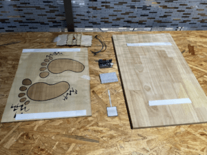
Here is a photo of our disassembly:
E. APPENDIX
Tinkercad wiring:
More photos:
F. CITATIONS
(code-specific citations have been left in the form of comments, but the audio file credits are listed here)
