
Prototyping Blog Documentation Week 14/Final Presentation Blog
For this final blog post, I will be recounting all the work and experiences I had the past eight weeks while creating my part of the Project Mjolnir bike, which is a storage system that utilizes the hollow pipes that comprise the bottom frame of the bike, which you can see here.
Week 1-5: Inspiration and Cardboard Prototyping
It first began with discussions with the Professor during the first few weeks of the class about additions to the bike that could make certain aspects to it mor convenient for use, to which one of these aspects was storage for repair tools for the bike. It was during that time that the idea of a tube storage system that utilized the hollow pipes of the frame of the bike was conceived. I would then create a cardboard prototype of the idea that had a consisted of a tube for the storage and a cap that would attach to both the outside of the pipe and the tube, which unfortunately I do not have pictures of but should be easy enough to imagine.
Week 6: Confirmation and More Inspirations
Things started to pick up during the construction of the actual bike during Week 6, in which I contributed a number of hours to helping construct it. It was during this time that I had solidified the idea for a tube storage system after having hands on experience with it. It was also during this time that I had a few other ideas in addition to the tube storage system, like more storage system that could be within the empty space of the bike.

Week 7: Mapping out/Sketching Ideas
During Week 7, I would come up with a few sketches for the storage systems I had in mind while having hands on experiences with the bike, which you can see below.
This was when I had a more solid idea for the tube storage system in terms of how it would be able to stay in the pipe and not fall out, which can see on the top of the sketch. The ideas were for the storage tubes would be able stay in the bike pipe via a screw in system and the other could stay in via a suction system similar to tennis ball containers.

In addition to the tube storage system, I had also come up with a number of other storage system methods that utilized the available spacing of the bike. This included a system that used grips attached to the wheel frames of the bike, a bag that could be attached to the seat, and storage bags that could be attached to the spaces between the bottom of the frame.
Week 8: Prototype Measuring and Refining
During Week 8, I created would create cardboard prototypes based on two of the storage systems in my sketches, which were the top right and bottom designs. I would take measurements of the respective spaces these designs would take up and measured, cut, and taped cardboard for mockups of the designs. However, after this I didn’t do much else for these designs as I was primarily focused on the tube storage system, so perhaps someone else can finish up with work I had started with these storage ideas.
Week 9: Learning a new prototyping tool – CAD
During Week 9, the class started to learn and use CAD to create computer models of our prototypes, to which I did so with the tube storage system as shown in the pictures below.


These two screenshots showcase the tube storage system itself, primarily the one that’ll cover up the bike tube once implemented. It will cover the bike tube via a screw on system on the left of the second screenshot, to which the bike tube will have a small device for the cap of the storage tube to screw on and in place in the bike tube. The idea then is that you can screw the cap off from the storage tube to be able to place items into the tube.
To take advantage of the bike tube length, I want to try make it so that multiple storage tubes are able to connect with one another for maximum storage and convivence. Me and the Professor took inspiration from a connective locking system from a gardening unit that has the following designs to be able to store individual plants onto one connective build, as shown below.


To which I, and with the help of the Professor, replicated in CAD as seen in the following screenshot.

The left part would be on the bottom of a respective storage tube and the right part would be where the hole of the tube would be where you could place items into. In practice, this should make it so that each tube would allow for another to connected and locked onto each other while closing off each respective tube as to prevent items from falling out. Each storage tube would also be identical and be able to fit with one another in a very convenient fashion. Thus, would create a system in which maximizes storage in a convenient and easy way.
Week 10: Modeling Adjustments
For Week 10, I continued to develop the models in CAD. With help from the professor, I created a new system in which that would be used to hold the storage units inside the bike tube. It would be done by inverting the thread to be so the storage cap would be inserted into the tube holder and being screwed into from there. Below is the previous iteration of the how the storage would be held in the bike tube with a large cap on top of a storage unit.
And here is a later iteration of the system designed later in the week.


It would still retain a cap as to prevent the tubes from falling out, but also be able to provide an additional storage space without wasting space.
Week 11: First Prints and More Adjustments
For Week 11, I continued further work on CAD and started printing out pieces of the project. We would print out a section of the storage tube and tube sleeve in order to test to make sure that both would be able to fit on and into the bike tube, to which both were able to fit.
Next we would print out the locking mechanism for the tube storage, which the first iteration printed could fit onto one another with sanding. So for the second iteration of print we adjusted the measurements for the lock mechanism to get them to fit without sanding. However, the printed mechanism isn’t able to work as intended either without sanding and thus needs further adjusting.
In the meantime, I figured out how to attach the cap to the tube sleeve and have part of the lock mechanism attached to it, as seen in the picture.

Week 12: Refining Print and Adjustments
For Week 12, I would continue work on CAD and printing out more pieces for testing. Namely we printed out the locking mechanism for the system, as you can see below. We had originally printed out a V1 of both the male and female parts of the locking system, but they weren’t able to fit with one another without sanding, so the measurements of the models in CAD were slightly adjusted to have them better fit, which you can see with the picture of V2 below.

Now it was a matter of making a tube locking mechanism that would be the right fit and secure for the V2 part. So far two more versions were printed, which had the little notches be sunk in by 0.2 and 0.4 mm respectively, but neither were able to rotate into the V2 labelled lock mechanism. You can see them in the picture below.

However, they would still not fit, and thus needed to be further reduced, to which the fitting measuring was about 0.75 mm, which was printed out the following week and confirmed to fit.
Week 13: More Prints and Final Adjustments
Speaking of which, for Week 13, aside from finally getting the measurements for the locking mechanism down, the tubes that use the locking mechanism were finally printed out and work as expected. During this week I also made more adjustments to the cap of the system, which went through a few more iterations like you see below.


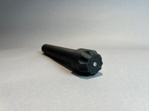
However, a new problem arose where the connection between the cap and male locking part is unstable when printed. Luckly this issue has been resolved by the professor by printing out the cap and connecting locking mechanism separately via separate screw that holds the two together. After that issue was solved, the last thing to do was change the cap to be more friendly to users when screwing and unscrewing, which I did so by making the following design below, which was based off of the Professor’s guide video.

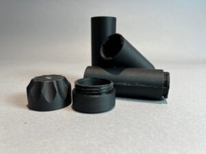
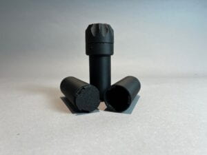
The following cap and more storage tubes were printed out this week and the results look to be expected and fit into one another well, which you can see below.

Week 14: Final Prints and Installations
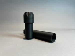
And finally, we come to Week 14, the last week of the entire semester and class. After all that, the latest versions and fixes of each component of the tube system had been printed out and fits perfectly, which you can the final results below.
The system was then installed onto the bike and worked as expected and perfectly. The Professor has pictures of it for reference.
Next Steps and Final Thoughts
In terms of next steps for this project, I was thinking of making several storage tubes of different lengths so that people can have the options of tubes that could serve their specific needs. Aside from that, outside the tube storage system, I was thinking continuing work on the storage systems I had made sketches of in Week 7, so that whoever is using the bike can carry as much as they need to for almost any situation.
In conclusion, I had a lot of fun and learned a lot the past semester in designing, adjusting, and creating. Before this class, I had the mindset of trying to get things right in the first try. But I now realize that isn’t always the case, and that it can take a number of design ideas, prototypes, and iterations to get things right. While time may not always permit it, it is best to utilize the time to make several iterations and changes in order to get the best possible product. But when you do have the time, be sure to make it as enjoyable as you can!
It has been an honor to have been a part of this project and part of history. I wish the best for Professor Noel and the team working on this project, and hopefully one day I can be a part of this project once more in some shape or form.