FINAL INDIVIDUAL REFLECTION: Sketcher for Equal Art

PROJECT TITLE – YOUR NAME – YOUR INSTRUCTOR’S NAME

Junyi(Stephen) Li – Rudi


CONCEPTION AND DESIGN:

Concept:

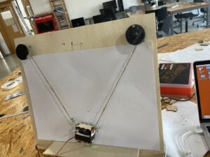
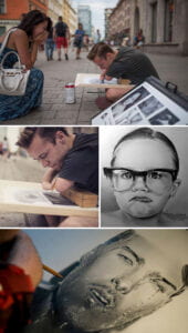
This project is intended to help hand disabled people to create the same sketching art as any one could. I have seen a Polish artist who was born without hands but through hard work, he managed to create sketching arts in his own unique way. Thus, to let people with hand disabilities sketch their own works comprehensively and more easily, I created this machine. By placing certain parts of one’s body on the touchpad of a computer, one can easily control the pen upon the paper to move around drawing things. I used 2 stepper motors to control the location of the pen and attached a servo to the pen, to that the pen can draw as if it is in the hand of a human. 

User test:

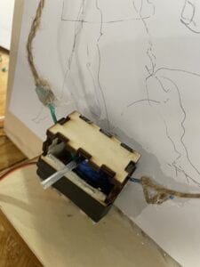
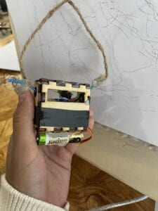
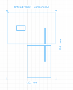
I showed the version 1 of my program in user testing and realized that the pen wasn’t stable enough to draw steadily, to change the situation I kept the pen and the servo in a wooden box and put weight under it as Andy suggested, so it can go around the paper more stably. 

Algorithms for location:

X and Y can represent any point in the graph so can the length of the two strings attached to the two steppers. It was like imaging the graph to be a curved screen. Any combos of the lengths of the two strings are as unique as the points on the graph. The location for the lengths of the strings of the the pen was calculated through the Pythagorean theorem. Assume that the coordinate of the my mouse is x and y and the whole graph was in 600×600 size. The left string length would be the square root of (x^2 + y^2) while the length of the right string is the square root of [(600-x)^2 + y^2)]. By giving the changes of length to Arduino and let the steppers step correspondingly would satisfy the need of changing the position of the pen on the paper. 

Fake Threading:

To let the servo and the 2 steppers run together simultaneously, I need to use threading which can manage so. I googled it and it told me that the SCoop library can help with that, but it turned out not so trustworthy as they said. Scoop still let missions proceed in sequence instead of going simultaneously. By checking the source code of Arduino, I realized that it was completely impossible for Arduino to proceed plural missions at the same time. Then, as Andy and Rudi instructed, I can have the two motors run little and little by  sequence. The intervals  between movements of the separate steppers can be so little that they can neglected. Thus, I decided to have a for loop to include them to work by turn rapidly. I decided the number of steps for each stepped differently, so they can run different lengths. There is still a problem that I can’t solve. Let’s say that the distances of left ad right that the steppers have to proceed were 125 and 175. By map() function, I change them from the arena of  -300 to 300 to the arena of -4 to 4, and they both turn out to be 2. Then, say we have a 75 times loop, the two steppers would both walk 150 steps. 

From Processing to Arduino:

It was always an issue when it came to “serialRead” that serialRead in Arduino actually can’t read negative numbers. To solve this problem, I have to add 300 to the massage sent by Processing and minus them by 300 in Arduino, so that stepper can finally approach they way I want it to work. 

FABRICATION AND PRODUCTION:

Frame and base design:

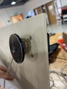
Compared to the coding and circuit parts, the construction of the wooden works was rather easy. What I need to do only was to make a huge frame to hold both drawing paper and the two steppers. Andy helped me a lot in the designing of the wooden work. He told me that instead of sticking the steppers across the board, I should nail the steppers against the board.  By using 4 nails, the steppers were successfully nailed onto the board. Whereas the cables could not go in rolls I wanted and the thin sticks of steppers can’t hold much strings. I borrowed two thick columns to how the strings and instead of using the cables as strings, I used thin transparent  plastic strings. However, I just realized that the plastic strings could easily go off the columns I used. I had to switch to thicker strings. Luckily, I found myself some thick paper strings so that the strings would not go off the columns so easily. 

Pen and Servo Holder:

I created the box in a website for wooden box creating recommended by Andy. I made a box at first but it didn’t fit so I changed the parameters and created a new one. They were measured so precise that they fitted so well for the servo and the pen attached to it. 

CONCLUSIONS:

I can say that it achieved my goal to help hand disabled people to sketch pictures so long as they can cater to the mechanism of this way of drawing. By simply placing any parts of one’s body to the touchpad of the computer, it could work. In the version one of my code, the goal was achieved, but the sketch would not be so precise. The second version worked fine after I modified certain parameters. To improve this project, I should keep changing the parameters used in Arduino and focus more on the details, say the showing of windows of Processing and performing the drawing on a larger paper. I should place more emphasis on the cosmetics of the subject. Moreover, I have realized that Arduino Uno, though said to be a low level platform, can achieve a lot of things. There is always a method for problems to be solved, and Arduino was not always to be blamed for the limited capability. The true limitation was the creation of the creator herself. I can even limit the stepping length so that the machine won’t always go out of the paper.

 ANNEX

Construction:
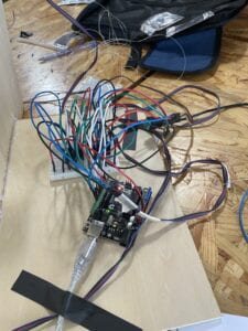
Final Project V1 for Arduino:

#include "SCoop.h"
#include "SerialRecord.h"
#include <Stepper.h>
const int stepsPerRevolution = 160;
Stepper leftStepper(stepsPerRevolution, 7, 6, 5, 3);
Stepper rightStepper(stepsPerRevolution, 8, 9, 10, 11);
#include <Servo.h>
Servo drawServo;
SerialRecord reader(2);
int val = 150;                                          

defineTask(TaskOne);
defineTask(TaskTwo);

void setup() {
  mySCoop.start();
}

void loop() {
 yield();
 delay(200);
}

void TaskOne::setup(){
  Serial.begin(9600);
  rightStepper.setSpeed(60);
  leftStepper.setSpeed(60);
}

void TaskOne::loop(){
  reader.read();
  if (reader[0] == 1){           
  leftStepper.step(-stepsPerRevolution);   
   }

 if (reader[0] == 2){           
  rightStepper.step(stepsPerRevolution);
  //delay(100); 
 }

if (reader[0] == 3){           
  leftStepper.step(stepsPerRevolution);
  //delay(100);
 }

if (reader[0] == 4){           
  rightStepper.step(-stepsPerRevolution);
  //delay(100);
 }
  reader[0] = 0;

}

void TaskTwo::setup(){    
  drawServo.attach(12);
}

void TaskTwo::loop(){    
  reader.read();
  if (reader[1] == 1){  
      drawServo.write(0);  
      delay(200);   
      drawServo.write(val);
    }
  reader[1]=0;
}

Final Project V1 for Processing:

import processing.serial.*;
import osteele.processing.SerialRecord.*;

Serial serialPort;
SerialRecord serialRecord;

void setup() {
  size(600,600);
  frameRate(30);
  strokeWeight(5);
  for(int x = 0; x <= 300; x += 300){
    for(int y = 0; y <= 300;y += 300){
      fill(random(255),random(255),random(255));
      rect(x,y,300,300);
    }
  }
  

  String serialPortName = SerialUtils.findArduinoPort();
  serialPort = new Serial(this, serialPortName, 9600);
  serialRecord = new SerialRecord(this,serialPort,2);
  
}

void draw() {
   if ((0 < mouseX) && (mouseX < 300) && (0 < mouseY) &&  (mouseY< 300)){
     serialRecord.values[0] = 1;
     
   }
     
  if ((0 < mouseX) && (mouseX < 300) && (300 < mouseY) &&  (mouseY< 600)){
     serialRecord.values[0] = 2;
  }
  
  if ((300 < mouseX) && (mouseX < 600) && (0 < mouseY) &&  (mouseY< 300)){
     serialRecord.values[0] = 4;
  }
  
  if ((300 < mouseX) && (mouseX < 600) && (300 < mouseY) &&  (mouseY< 600)){
     serialRecord.values[0] = 3;
  }
  delay(200);
}

void mousePressed(){
  serialRecord.values[1] = 0;
  serialRecord.send();
   delay(200);
}

void mouseReleased(){
  serialRecord.values[1] = 1;
  serialRecord.send();
   delay(200);
}

Final Project V2 for Arduino:

#include "SCoop.h"
#include "SerialRecord.h"
#include <Servo.h>
#include <Stepper.h>
const int stepsPerRevolution = 160;
Stepper leftStepper(stepsPerRevolution, 7, 6, 5, 3);
Stepper rightStepper(stepsPerRevolution, 8, 9, 10, 11);
Servo drawServo;
SerialRecord reader(3);
int val = 180;

defineTask(TaskOne);
defineTask(TaskTwo);
defineTask(TaskThree);

void TaskOne::setup(){
  reader[0]=0;
  reader[1]=0;
  reader[2]=0;
  Serial.begin(9600);
  leftStepper.setSpeed(30);
  drawServo.attach(12);
}

void TaskOne::loop(){
  reader.read();
  leftStepper.step(reader[0]);
  reader[0]=0;
}

void TaskTwo::setup(){
  Serial.begin(9600);
  rightStepper.setSpeed(30);
  drawServo.attach(12);
}

void TaskTwo::loop(){
  reader.read();
  rightStepper.step(reader[1]);
  reader[1]=0;
}

void TaskThree::setup(){
  Serial.begin(9600);
  drawServo.attach(12);
}

void TaskThree::loop(){
  reader.read();  
  if (reader[2] == 1){  
      drawServo.write(0);  
      delay(500);   
      drawServo.write(val);
      reader[2] = 0;
  }
}

void setup() {
  mySCoop.start();
}

void loop() {
 
 yield();
 
}

Final Project V2 for Processing:

import processing.serial.*;
import osteele.processing.SerialRecord.*;

Serial serialPort;
SerialRecord serialRecord;

float beginX = 150;  // Initial x-coordinate
float beginY = 150;  // Initial y-coordinate
float endX = 150;   // Final x-coordinate
float endY = 150;   // Final y-coordinate
float distX;          // X-axis distance to move
float distY;          // Y-axis distance to move
float exponent = 4;   // Determines the curve
float x = 0.0;        // Current x-coordinate
float y = 0.0;        // Current y-coordinate
float step = 0.01;    // Size of each step along the path
float pct = 0.0;      // Percentage traveled (0.0 to 1.0)
float beginl1;
float beginl2;
float endl1;
float endl2;
float dstl1;
float dstl2;


void setup() {
  
  size(500, 500);
  noStroke();
  distX = endX - beginX;
  distY = endY - beginY;
  
  String serialPortName = SerialUtils.findArduinoPort();
  serialPort = new Serial(this, serialPortName, 9600);
  serialRecord = new SerialRecord(this,serialPort,3);
}


void draw() {

  fill(0, 2);
  rect(0, 0, width, height);
  
  pct += step;
  
  if (pct < 1.0) {
    x = beginX + (pct * distX);
    y = beginY + (pct * distY);
  }
  
  fill(255);
  ellipse(x, y, 20, 20);
  
  pct = 0.0;
  
  beginX = x;
  beginY = y;
  
  endX = mouseX;
  endY = mouseY;
  
  distX = endX - beginX;
  distY = endY - beginY;
  
  beginl1 = dist(beginX,beginY,0,0);
  beginl2 = dist(beginX,beginY,300,0);
  
  endl1 = dist(endX,endY,0,0);
  endl2 = dist(endX,endY,300,0);
  
  dstl1 = endl1 - beginl1;
  dstl2 = endl2 - beginl2;
  
  serialRecord.values[0] = int(dstl1) + 300;
  
  serialRecord.values[1] = int(dstl2) + 300;
  
  if (mousePressed == true){
    serialRecord.values[2] = 1;
  
    serialRecord.send();
  } else {
    serialRecord.values[2] = 0;
  
    serialRecord.send();
  }
 
}

Final Project V3 for Processing:

#include "SCoop.h"
#include "SerialRecord.h"
#include <Servo.h>
#include <Stepper.h>
const int stepsPerRevolution = 360;
Stepper leftStepper(stepsPerRevolution, 7, 6, 5, 3);
Stepper rightStepper(stepsPerRevolution, 8, 9, 10, 11);
Servo drawServo;
SerialRecord reader(3);
int val = 180;
defineTask(TaskOne);
defineTask(TaskTwo);

void TaskOne::setup(){
 
 Serial.begin(9600);
}

void TaskOne::loop(){
 reader.read();
 leftStepper.setSpeed(120);
 rightStepper.setSpeed(120);

 int leftSteps = map(reader[0]-300,-200,200,-5,5);
 int rightSteps = map(reader[1]-300,-200,200,-5,5);

 for(int i=0; i<18; i++){
  leftStepper.step(leftSteps/3);
  rightStepper.step(rightSteps/3);
 }

reader[0] = 300;
reader[1] = 300;
}

void TaskTwo::setup(){
 Serial.begin(9600);
}
void TaskTwo::loop(){
  reader.read();
  if (reader[2] == 1){  
      drawServo.write(0); 
      drawServo.write(val);
      reader[2] = 0;
  }
}

void setup() {
 reader[0]=300;
 reader[1]=300;
 reader[2]=0;
 mySCoop.start();
}

void loop() {
 yield();
}

Version 1:

Version 2:
Recitation 10: Image & Video

The codes for this recitation was rather easy.  I didn’t meet fatal troubles, but one significant thing did strike me, that the high frequency of Arduino’s sending info to Processing does not necessarily result in fast response in Processing. Instead, it was rather important to choose the right frequency of sending info by adequate “delay(m).”

Video:

code for Processing: 

import processing.video.*;
import processing.serial.*;
import osteele.processing.SerialRecord.*;

Serial serialPort;
SerialRecord serialRecord;

String[] cameras = Capture.list();
Capture cam;

void setup() {
  size(640, 480);
  printArray(cameras);
  cam = new  Capture(this, "pipeline:autovideosrc");
  cam.start();
  
  String serialPortName = SerialUtils.findArduinoPort();
  serialPort = new Serial(this, serialPortName, 9600);
  serialRecord = new SerialRecord(this, serialPort, 1);

}

void draw() {
  if (cam.available()) {
    cam.read();
  }
  serialRecord.read();
  int value = serialRecord.get();
  float x = map(value,0,1000,0,255);
  image(cam, 0, 0);
  x = int(x);
  tint(x);
  
}

code for Arduino:

#include "SerialRecord.h"
SerialRecord writer(1);
int rest = A0;


void setup() {
Serial.begin(9600);
}


void loop() {
int X = analogRead(rest);
writer[0] = X;
writer.send();
delay(20);
}

Recitation 9: Digital Fabrication

The design:

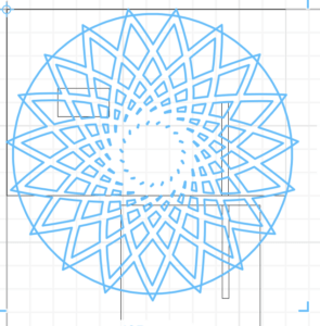
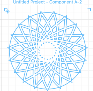
For lower structure: it was rather easy.

the Upper structure: I can’t eliminate the small spaces close to the center and I have tried multiple initial shapes, but still it didn’t work out.

The video recording of the process:

Fabrication:

Product:

Recitation 8: Serial Communication

Task #1:

My processing and Arduino framework provided a hyper-sensitive interaction, as could be seen in the two video recorded as following IMG_2934 IMG_2935. A minor mistake in the code that had generated this issue, the pinModes for the potentiometers were adjusted as “OUTPUT”. Thus, instead of recording the changes in resistance, it recorded as outputs the potentiometers. 

Code for Processing:

import processing.serial.*;
import osteele.processing.SerialRecord.*;

int x1 = 0;
int x2 = 1450;

Serial serialPort;
SerialRecord serialRecord;

void setup() {
  fullScreen();
  frameRate(30);


  String serialPortName = SerialUtils.findArduinoPort();
  
  serialPort = new Serial(this, serialPortName, 9600);
  
  serialRecord = new SerialRecord(this,serialPort,2);
}

void draw() {
  background(0);
  noStroke();
  if (x1 == 1450 && x2 == 0){
   x1 = 0;
   x2 = 1450;
   serialRecord.values[0] = 0;
   serialRecord.values[1] = 1;
   serialRecord.send();
  }
  
  if (x1 == 0 && x2 == 1450){
    
   serialRecord.values[0] = 1;
   serialRecord.values[1] = 0;
   serialRecord.send();
  }


  if (x1<1450) {
    circle(x1, 550, 50);
    x1=x1+50;
    x2 = 1450;
    serialRecord.values[0] = 0;
    serialRecord.values[1] = 0;
    serialRecord.send();
  } else {
    circle(x2, 550, 50);
    x2=x2-50;
    serialRecord.values[0] = 0;
    serialRecord.values[1] = 0;
    serialRecord.send();
  }
}

Code for Arduino:

#include "SerialRecord.h"
SerialRecord writer(2);

int pinX = A0;
int pinY = A1;

void setup() {
  // put your setup code here, to run once:
  Serial.begin(9600);
  // pinMode(pinX,OUTPUT);
  // pinMode(pinY,OUTPUT);
}

void loop() {
  // put your main code here, to run repeatedly:
  int X = analogRead(pinX);
  int Y = analogRead(pinY);
  writer[0] = X;
  writer[1] = Y;
  
  writer.send();
  delay(10);
}

Task2:

Teammate: Tawan

Our code was absolutely fine throughout the process. The inefficiency was caused by some matters in Arduino and Processing system. Before we embedded the code that sent messages to Arduino, the circle bounced back and forth just fine after we simply managed the coordinates of borders. But once the code was embedded while  there was no wrongs in grammar or mechanism of the Arduino code, Processing gave us all blank output when Arduino had sent the code of Arduino to Arduino Uno. It always said “port busy” in Processing. So, we shut it but the servo once received the message started moving forever non-stop. Thus,  I have to forcefully made it stop by changing the Processing-sent value. After thousands of tries, I added two led lights to the servo to see if it was the problem with the servo. Surprisingly, the servos started to work fine. The interaction of the device was very much low-level, machine-to-machine, pale single-direction signal. However, it did stroke me that for Arduino-Processing artifacts, codes should be sent to the Arduino Uno first and I should shut the Arduino thoroughly before proceeding to Processing. 

Recordings:

Code for Processing:

import processing.serial.*;
import osteele.processing.SerialRecord.*;

int x1 = 0;
int x2 = 1000;
Serial serialPort;
SerialRecord serialRecord;

void setup() {
  fullScreen();
  frameRate(30);


  String serialPortName = SerialUtils.findArduinoPort();
  
  serialPort = new Serial(this, serialPortName, 9600);
  
  serialRecord = new SerialRecord(this,serialPort,2);
}

void draw() {
  background(0);
  noStroke();
  if (x1 == 1450 && x2 == 0){
    x1 = 0;
    x2 = 1450;
   serialRecord.values[0] = 0;
   serialRecord.values[1] = 1;
   serialRecord.send();
  }
  
  if (x1 == 0 && x2 == 1450){
   serialRecord.values[0] = 1;
   serialRecord.values[1] = 0;
   serialRecord.send();
  }


  if (x1<1450) {
    circle(x1, 550, 50);
    x1=x1+50;
    x2 = 1450;
    serialRecord.values[0] = 0;
    serialRecord.values[1] = 0;
    serialRecord.send();
  } else {
    circle(x2, 550, 50);
    x2=x2-50;
    serialRecord.values[0] = 0;
    serialRecord.values[1] = 0;
    serialRecord.send();
  }
}

Code for Arduino:

#include "SerialRecord.h"
#include <Servo.h>
int led1 = 12;
int led2 = 13;
Servo servo1;
Servo servo2;
SerialRecord reader(2);
int val = 180;

void setup() {
  Serial.begin(9600);
  servo1.attach(7);
  servo2.attach(4);
  pinMode(led1,OUTPUT);
  pinMode(led2,OUTPUT);
}

void loop() {
 reader.read();

 if (reader[0] == 1){           
  servo1.write(val);
  delay(100);  
  servo1.write(0);
  reader[0] = 0;
  digitalWrite(led1, HIGH);   // turn the LED on (HIGH is the voltage level)
  delay(100);                       // wait for a second
  digitalWrite(led1, LOW);    // turn the LED off by making the voltage LOW
  delay(100);                 

 }

 if (reader[1] == 1){           
  servo2.write(val);   
  delay(100);          
  servo2.write(0);
  reader[1] = 0;
  digitalWrite(led2, HIGH);   // turn the LED on (HIGH is the voltage level)
  delay(100);                       // wait for a second
  digitalWrite(led2, LOW);    // turn the LED off by making the voltage LOW
  delay(100);                 
 }
}

PROPOSAL ESSAY

Sketching Arts from the Hand-disabled: Sketch Your Dreams with Sketch-it

Project Statement of Purpose

The interactive designs I explored triumphed not over the high-tech they included but the interaction they provided for the audience and it was often the case that success of the projects was the graphitization  of people’s mindset or mentality. It stroke me that sketching was also a way to express one’s mindset graphically. Though a simple work of hand, it was almost impossible for many people with hand disabilities and even if they can manage so, it would take great efforts. Thus, the project aims to help people with hand disabilities to accomplish their dream of sketching art, to help them express themselves of sketching in an easier way. 

Project Proposal Plan

The project was basically a robotic sketcher, consisting of two stepper motors hanging on a drawing mat vertical to the ground, which were attached with two strings connected to one servo whose fans were combined with a pencil. On key board, people can control the servo to have the pencil sketching in half circles by clicking the mouse and relocate the pencil on the drawing mat by moving the mouse. The setting up of such device, including laser cuttings and 3D printing, would take about three days to finish without concerning other urgent missions from other courses that I need to accomplish while the code of it would take about one day or three depending on whether I will have time to finish the harder but more interactive version of the code. Starting from the easy version, when the code in Processing is run, the interface would be split into 4 areas correspondingly to four directions of the movements of the servo with pencil, up-left, up-right, down-left, and down-right. For example, when the mouse is placed in up-left area, the stepper motor at the up-left corner of the drawing mat would start rolling to shorten the string attached to the left side of the servo so that it moves in the up-left direction. The harder version would take algorithms. There would not be specific indications of where to place the mouse to have the servo moving towards specific directions. Instead, by tracing the trail of the movement of the mouse, the servo would move to the location on the mat corresponding the location of the mouse in the interface of Processing. Moreover, I wanted to add a variable to adjust the rotation of the servo so that the pencil doesn’t always draw half circles. The variable could be changed according to the strength applied to a force sensor. 

Context and Significance

 I think in this project, it was fulfilled. There was a successful work, Supersynthesis by Amay Kataria which visualized the music produced by people in the periodical glowing of lights according to notes and melodies.( n.d.) Amay Kataria described the purpose of the art is to visualize people’s minds (mediations) in the form of lights per se.( n.d.) I think sketching was also a direct way of speaking from one’s mind in the form of visuals. Though it was easy for us to sketch with a few techniques of drawing, it was hard enough for people with hand disabilities to draw. There is a Polish artist called Mariusz Kedzierski, who was born without hands, but succeeded in making a career though sketching with his arms hold pencils. His works of art were still on sale in his personal website, https://www.mariuszkedzierski.net, and captured multiple global prizes. He was such an inspiring power for people that he became a motivational speaker influencing the world. (Bern, n.d.) 

Interactions, in the perspective of Interactive Media Art, from my perspective would be the comprehensive indications and responses from/for human users that are received and generated from/for electronic artifacts. Processing understands the movements and clicking of mouse while the users, on seeing what have been drawn on the mat could decide her next move to make. The project aims its target audience specifically at the hand-disabled, but doesn’t limit its users or audience within such. The terminal ideology of the project was intended to help people with hand disabilities produce their graphic work of art in sketches. By the works of arts produced, the recordings of production of arts by these people and the mechanisms of the device, more social attention could be drawn to hand-disabled people, to whom more help should be offered, instead of marginalizing. 

References

Dockery, Regan. “Light & Sound Synthesis: In Conversation with Amay Kataria.”interviewed  by Regan Dockery. In Environment Sound. Can-V5. Creative Applications. 2022. Accessed Nov. 15th, 2022. https://www.creativeapplications.net/environment/light-sound-synthesis-in-conversation-with-amay-kataria/.

Bern, Marija. “We Can’t Believe What These 37 Artists Can Do Despite Their Disabilities.” In Art, People. BoredPanda. 2018. Accessed Nov. 20th, 2022. https://www.boredpanda.com/inspiring-disabled-artists/?utm_source=google&utm_medium=organic&utm_campaign=organic.

THREE PROJECT PROPOSALS

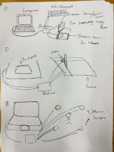
  1. YourBeat: Musics played by the official music apps might not cater to one’s taste. Despite the matters of the lyrics, the beats and the melodies could also be a problem. Meanwhile it was sometimes the case that by adding certain beats of certain comparative volume to the music can promote the music and incline the engagement of audience to a whole new level. YourBeat, a simple device could manage such. When music played, visualized music as varying columns generated by  Processing, would show in the 8*32 Neo-pixel. By motions above the distance sensor, the volume of the music could be adjusted while by one motion above the motion sensor, the beat could be played once. Thus, by simply shaking hands above the motion sensor, beats of your own could be added to the music, and visualized on the Neo-pixel. 
  2. Sketcher: The device was intended for people with disabilities in hands, to say missing fingers or hands, that disabled them from sketching. Sketching needed high intensity of vibrations and oscillations of pencils, so would be rather hard for people with such disability to manage. Thus, I designed this device, which is made up of servo, pencil and a machine that could move the servo around according to the movement of mouse by contacting with the touchpad. By pressing the touchpad, the servo attached with a pencil would run by once. Meanwhile, by contacting the touch pad, the pencil could be moved to the corresponding location to the attachment of the touchpad of the frame that holds it. 
  3. Move-up: There’s a kind of games called MUG (Music Game) that originated in Japan and around gained its prevalence around the world. The game was also labeled as a specific kind of game for “otaku”, homebody or indoorsman. Thus, to switch this label for the game and shad light on the health of this group of people for lack of physical exercise, I decided add on more movements to the game. To physicalize it from the screens to physical movements. Four motion sensors would be able to capture users’ movements to encourage them to win the game by moving certain body parts to the corresponding motion sensor following the beats or nodes of the music played. 

The following is the sketch for three devices. 

Recitation 7: Neopixel Music Visualization

Task 1:

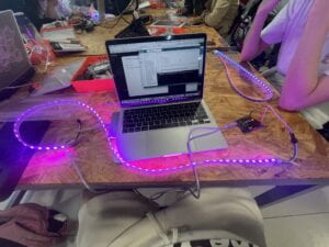
I managed to connect the cable, which took me about 1 min. FastLed has already been downloaded before the recitation. From the material, I learnt to give supply for the larger pixel boards to glow the same way.

Task 2:

I lit up accordingly, the second light in purple. To be seen in the link. 

IMG_2916

On copying the code, I produced the scene below. 

IMG_2884

Task 3:
 I tried to let all the pixels’ colors change with the sound but I can’t. And found out that it was the problem with the “constrain” function. On changing “constrain” to “map” . “map” was very useful a function that by ratio, it could turn a variable from one range to another correspondingly while “constrain” only limited a variable within the maximum and minimum. This is the situation before the change. 

IMG_2885

This is after. 

IMG_2887

It is such an ambiguity that I wanted it to be all purple and only bring changes on the saturability of purple. 

/* This is a code example for Processing, to be used on Recitation 7
  You need to have installed the SerialRecord library.
  
  Interaction Lab
  IMA NYU Shanghai
  2022 Fall
*/
import processing.sound.*;
import processing.serial.*;
import osteele.processing.SerialRecord.*;
SoundFile sample;
FFT fft;
int bands =256;
float smoothingFactor = 0.2;

Serial serialPort;
SerialRecord serialRecord;

float[] sum = new float[bands];
int scale = 8;
float barWidth;


int W;         //width of the tiles
int NUM = 255;  //amount of pixels
int[] r = new int[NUM]; //red of each tile
int[] g = new int[0]; //green of each tile
int[] b = new int[NUM]; //blue of each tile

void setup() {
  size(1024, 768);
  background(255);
  barWidth = 10*width/float(bands);
  sample = new SoundFile(this, "Post Malone - A Thousand Bad Times.mp3");
  
  // You can use this syntax and change COM3 for your serial port
  // printArray(Serial.list());
  // serialPort = new Serial(this, "COM3", 9600);
  // in MacOS it looks like "/dev/cu.usbmodem1101"
  //or you can try to use this instead:
  fft = new FFT(this, bands);
  fft.input(sample);
  String serialPortName = SerialUtils.findArduinoPort();
  serialPort = new Serial(this, serialPortName, 9600);
  
  serialRecord = new SerialRecord(this, serialPort, 4);
  serialRecord.logToCanvas(false);
  
  rectMode(CENTER);
}

void draw() {
  background(125, 255, 125);
  fill(255, 0, 150);
  noStroke();
  
  fft.analyze();
  
  //int n = floor(constrain(mouseX/W , 0, NUM-1));
  //r[n] = floor(255);
  //g[n] = floor(random(255));
  //b[n] = floor(255);
  
  for (int i = 0; i < 32; i++) {
    // Smooth the FFT spectrum data by smoothing factor
    sum[i] += (fft.spectrum[i] - sum[i]) * smoothingFactor;

    // Draw the rectangles, adjust their height using the scale factor
    rect(i*barWidth, height, barWidth, -sum[i]*height*scale);


      r[i] = floor(255);
      g[i] = floor(random(255));
      b[i] = floor(255);
      
      serialRecord.values[0] = i;     // which pixel we change (0-59)
      serialRecord.values[1] = r[i];  // how much red (0-255)
      serialRecord.values[2] = g[i];  // how much green (0-255)
      serialRecord.values[3] = b[i];  // how much blue (0-255)
      serialRecord.send();            // send it!
    
  }
}

void mousePressed(){//点击鼠标
 if(sample.isPlaying()){//如果声音在播放
   sample.pause();//暂停
 }else{//否则
   sample.loop();//播放声音
   //play()函数只播放声音一次
 }
}

But errors on behalf of the drive appeared. It said so:

SLF4J: Failed to load class “org.slf4j.impl.StaticLoggerBinder”.
SLF4J: Defaulting to no-operation (NOP) logger implementation
SLF4J: See http://www.slf4j.org/codes.html#StaticLoggerBinder for further details.
RuntimeException: Error opening serial port /dev/cu.usbmodem11301: Port busy

Final Project: PREPARATORY RESEARCH AND ANALYSIS

Interactions, in the perspective of Interactive Media Art, from my perspective would be the comprehensive indications and responses from/for human users that are received and generated from/for electronic artifacts. These interactions are limited in the very standard that they should be comprehendible bi-directionally. That is to say, machine can understand and proceed the indications from human users and give back corresponding reposes, and vice versa. The two spheres of interaction acquire the equivalent level and amount of knowledge in the aspect of the specific interaction(s), right enough for proceeding inputs and outputs. 

On the development of science and technology, interactive art emphasized more and more  on the compromise of machines and the naturality of human actions. Instead of giving indications to the users that limit users actions within certain disciplines, machines are more and more able to sense natural movements of human users. As the third kind of Interaction engagement and experience defined by Ernest Edmonds (n.d.),  non-invasive devices captured audience movements with sensors and generate certain responses. I think this category of devices is what I think of as the final project that I am going to produce. Thus, I did researches on projects concerning such:

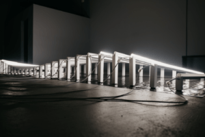
First, Supersynthesis. According to the standards raised by Ernest Edmonds, the time spent by the processing of inputs and the generating of outputs result in the interactivity of the project. The project gave immediate responses as the signals of flashing light according to the sound given by the users. Basically, it was a visualization of sounds, but according to the creator of it, Amay Kataria, the lights of it, “were repeatedly brought up to express guidance, clarity, and direction in their own inner journeys of spiritual practice”.  ( n.d.)(Dockery, n.d.)

The lights were complied into waves to express waves of sounds. When sounds came, the lights cooperated to glow with the beats and generated waves of shines. What’s even special about it is that the glow left by former users would be recorded and promoted to the device again. The success of this artifact was that it itself was only a half product, and it left huge space for the audience to finish this art, which caters to the interaction art raised by Ernest Edmonds, to let the audience finish the rest of the piece.(n.d.) 

Second, the MIDI Experiments. Mark Wheeler generated two animations that could vary with the changing of the sound input.(n.d.) As could be seen below, the key pressed, the animation started producing pictures accordingly. 

(Eats, n.d.)

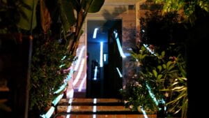
Then, Russ Chimes and Clay Weishaar, abstract the two experiment from the screen to reality, by a gargantuan amount  of projectors. They created the tunnels of lights in suburbia. (Visnjic, n.d.) The artifact, like the former gave immediate reactions from the input of users and that the art of it was made varying by the users. It created a visual reality for the users, bringing them into a suburbia that was renewed by the lights. 
Conclusion:

The most significant essence of success of these interactive arts was the remaining blank of the art to be completed by the audience. They, in my understanding, are half-products before the participation of the audience. But as long as the actions of audience detected, they generated complete arts. No strong indications needed. No invasive devices used. No specific or instructed actions needed to be done on the audience part. The actions of audience were just captured and abstracted to the outputs. Machines and audience acted as co-artist to produce a great piece of visual reality on their comprehensive understanding of each others’ reactions and indications. The advanced usage of science and technology, by no doubt, contributed to the success of the two artifacts. But more importantly, they invited the audience to join the creation of art, the visualization of audience’s mentality, while keeping the naturality of human movements, which could be described as “Dynamic-Interactive (Communicating) art systems”(Edmonds, n.d.). The lasting outputs, the combinations of lights are “Attracting”; the  varyings, the oscillation and vibration of lights are “Sustaining”; On the short time that were needed for the changes activated by the audience to show, they are very much “Relating”.(Edmonds, n.d.) The triumph of interactive arts depends not on the many sensors, detectors or high-techs used, but that how much it could interact with the audience, how much naturality can be kept for the audience and how the outputs vary and perceived by the audience. 

Works Cited

Dockery, Regan. “Light & Sound Synthesis: In Conversation with Amay Kataria.”interviewed  by Regan Dockery. In Environment Sound. Can-V5. Creative Applications. 2022. Accessed Nov. 15th, 2022. https://www.creativeapplications.net/environment/light-sound-synthesis-in-conversation-with-amay-kataria/

Edmonds, Ernest. “Introduction.” In Art, Interaction and Engagement. N.d. https://drive.google.com/file/d/1YYyhVTtNTBXQP2dlK8vE_QRJnpmCGvTE/view

Eats, Mark. “MIDI Visualizer Experiment 2.” Vimeo. https://vimeo.com/90654648?embedded=true&source=vimeo_logo&owner=443954

Visnjic, Filip. “Visual Sound Experiments – Transforming Suburbia with Light and Sound.” In Members openFrameworks Sound. Can-V5. Creative Applications. 2022. Accessed Nov. 15th, 2022. https://www.creativeapplications.net/sound/visual-sound-experiments-transforming-suburbia-with-light-and-sound/

Recitation 6: Animated Poster

Recitation

void setup(){
  size(1024,768);
  background(255);
  noStroke();
 
  for (int i = 0; i < 768; i += 1) {
    
    fill(i/4,1/3,i/2);
    rect(0,i,1024,1);
    
  }
}

void draw(){
  strokeWeight(10);
  fill(random(255),random(255),random(255));
  circle(random(1024),random(768),random(255));
  delay(1000);
  //background(random(255),random(255),random(255));

}
void mousePressed(){
   circle(float(mouseX),float(mouseY),random(100,300));
}

void mouseReleased() {
  
  textSize(128);
  text("recitation", mouseX, mouseY); 
  fill(0, 408, 612);
  text("rectitation",mouseX, mouseY+40);
  fill(0, 408, 612, 204);
  text("recitation", mouseX, mouseY+40);
}

The video is here. Click it to open. I don't want my personal info going onto YouTube. Nor do I know how to transform mov to mp4 on Mac. 
IMG_2826
void setup(){
  size(1024,768);
  background(255);
  noStroke();
 
  for (int i = 0; i < 768; i += 1) {
    
    fill(i/4,1/3,i/2);
    rect(0,i,1024,1);
    
  }
}
void mousePressed(){
   circle(float(mouseX),float(mouseY),random(100,300));
}

void mouseReleased() {
  
  textSize(128);
  text("recitation", mouseX, mouseY); 
  fill(0, 408, 612);
}
void draw(){
  strokeWeight(10);
  fill(random(255),random(255),random(255));
  circle(float(mouseX),float(mouseY),random(255));
  delay(100);
  //background(random(255),random(255),random(255));

}

Here is an upgraded version of the poster. 
upgraded version
Homework 

int x;
int y;

void setup(){
  size(1024,768);
  background(255);
  noStroke();
  for (int i = 0; i < 768; i += 1) {
    fill(i/2,i/3,i/4);
    rect(0,i,1024,1);
  }
}
void draw(){
  if (mousePressed == true){
    for (int x = 0; x <= 4; x += 1){
      for (int y = 0; y <= 3; y += 1){
        if ((x*256 < mouseX) && ((x+1)*256 > mouseX) && (y*256 < mouseY) && ((x+1)*256 > mouseY)) {
          fill(random(255),random(255),random(255));
          arc(128+x*256,128+y*256,random(100,256),random(100,256),QUARTER_PI,PI + PI);
          fill(random(255),random(255),random(255));
          arc(192+x*256,64+y*256,25,25,0,PI + PI);
        }
      }
    }
  }
  delay(100);
  
}

Task 1
屏幕录制2022-11-08 12.17.12
Task 2
屏幕录制2022-11-08 12.24.04
Task 3
屏幕录制2022-11-08 14.21.12 The code for Task 3 is above. 


I have learnt to draw different ellipses in multiple ways, circles(), ellipse(), and arc(), and I learnt to use them corresponding to different needs. I knew the collective conditions to be used by if. I have learnt how to command mouse to control the output in the exhibiting stage, in which mousePressed, mouseReleased were used and mouseX, mouseY could locate the mouse. I have also learnt to use stroke to adjust edges of patterns while filling colors was a piece of cake.

Recitation 5: Processing Basics

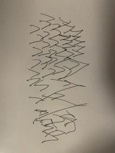
Initially, I want to draw a face of a man. But on the piece of paper given, I realized that no matter how I draw, it would be too hard to find the exact coordinates corresponding to each dot that I used. Thus, I decided to make something that went more randomly, to say, grass. 

This was the graph that I wanna draw, but then I realized that it was kind of hard to draw because of all those lines and shapes of grass. So I wanted it automatically done. Thus, I made the following. 

The code is here. 

void setup() {
size(800,800);
strokeWeight(10);
background(255);
}
void draw() {

fill(0,200,100);
beginShape();
vertex(0,700);
vertex(100,80);
vertex(200,400);
vertex(300,80);
vertex(400,500);
vertex(500,80);
vertex(600,400);
vertex(700,80);
vertex(800,700);
endShape();
color(100,100,100,100);
fill(0,200,150);
for (int i = 0; i < 40; i+=10) {
bezier(
width/2, height,
width/2, random(height),
random(width), random(height),
random(width), random(height)
);
}
}