All posts by Jenna Sun
Recitation 3: Sensors (9.30.22)
For this week’s recitation, we used a tilt switch to build a wearable workout sensor.
Materials
- 1 * Arduino Uno
- 1 * USB A to B cable
- 1 * breadboard
- 1 * tilt switch
- 1 * 10k ohm resistor
- A handful of M/F, M/M, and F/F cables
- 2 long wires (about 1.8 m)
- 1 capacitor 0.1 uF (confirm size)
Step 1: Prepare tilt sensor
Task #1: Solder the sensor to two long wires.
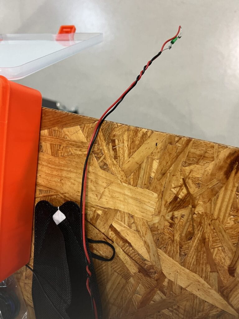
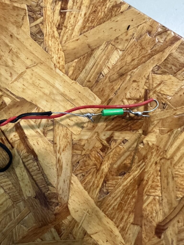
Task #2: Connect the tilt sensor cables to your Arduino using a capacitor as the circuit below:
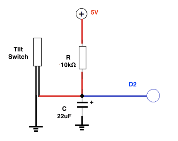
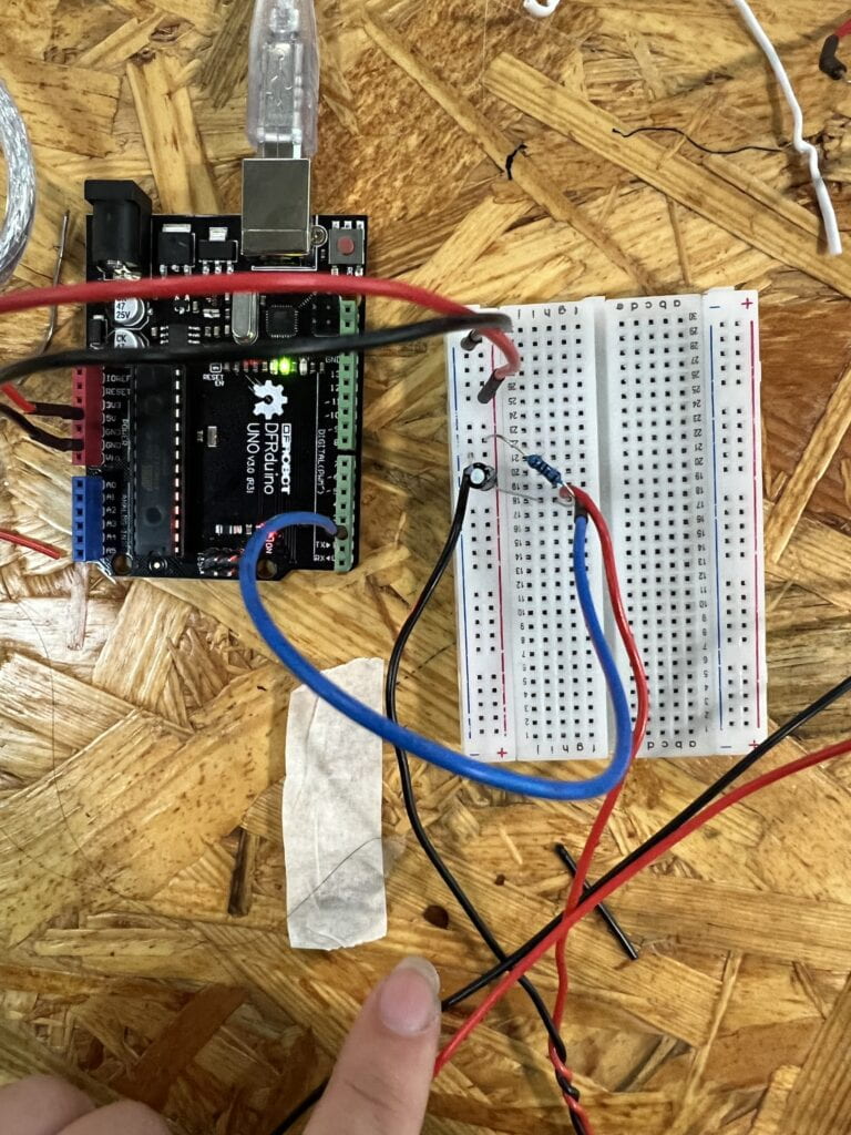
Originally connected the switch directly to power, but it should be connected through the resistor and then capacitor.
Task #3: Program your Arduino with the following sketch. Confirm that you get an input from your tilt sensor on the the Serial Monitor to check whether it is working correctly.
int SENSOR_PIN = 2;
int tiltVal;

void setup() {
  pinMode(SENSOR_PIN, INPUT);    // Set sensor pin as an INP
  Serial.begin(9600);
}

void loop() {
  // read the state of the sensor
  tiltVal = digitalRead(SENSOR_PIN);
  Serial.println(tiltVal);
  delay(10);
}
Step 2: Refine the code
Task #1: Upload the following sketch to only print 1 when the tilt sensor changes from 0 to 1, and 0 when from 1 to 0. For example, the code we used before might have printed 0 0 0 0 1 1 1 1 0 0 0 0 1 1 1 as you move the sensor between upright and upside-down, but now your code should print 0 1 0 1.
int SENSOR_PIN = 2;
int tiltVal;
int prevTiltVal;

void setup() {
  pinMode(SENSOR_PIN, INPUT); // Set sensor pin as an INPUT pin
  Serial.begin(9600);
}

void loop() {
  // read the state of the sensor
  tiltVal = digitalRead(SENSOR_PIN);
  // if the tilt sensor value changed, print the new value
  if (tiltVal != prevTiltVal) {
    Serial.println(tiltVal);
    prevTiltVal = tiltVal;
  }
  delay(10);
}
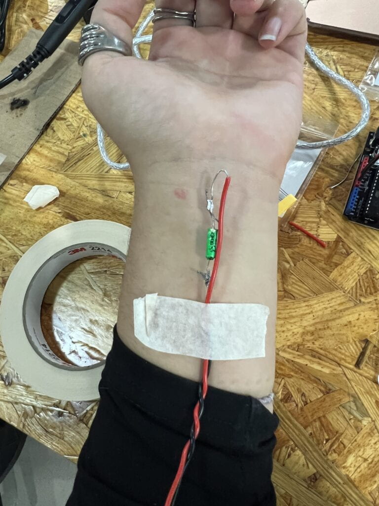
Step 3: Wear the sensor
Step 4: Bicep curl workout
Task #1: Add a conditional to your sketch so that it shows a message on the Serial Monitor ONLY when a full biceps curl has been completed. Remember to switch from the Serial Plotter to the Serial Monitor. You can comment existing lines of code with //.
- Identify the proper section in your code where you can add code when transitions happen.
- Add a conditional that has the criteria so that you only detect transitions LOW to HIGH, showing only when the user has raised their arm completely.
int SENSOR_PIN = 2;
int tiltVal;
int prevTiltVal;

void setup() {
  pinMode(SENSOR_PIN, INPUT); // Set sensor pin as an INPUT pin
  Serial.begin(9600);
}

void loop() {
  // read the state of the sensor
  tiltVal = digitalRead(SENSOR_PIN);
  // if the tilt sensor value changed, print the new value
  if (tiltVal != prevTiltVal) {
    if (tiltVal == 1) {
    Serial.println(tiltVal);}
    prevTiltVal = tiltVal;
  }
  delay(10);
}
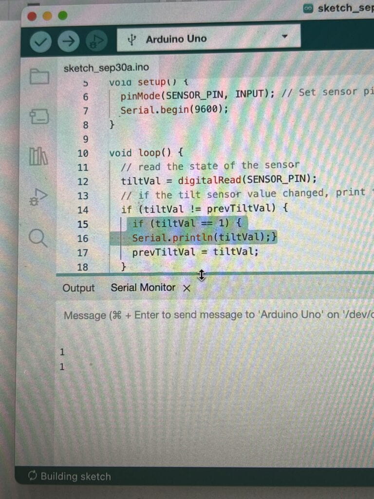
I didn’t know what a conditional was, one of the LAs helped me understand it. A conditional is an “if” statement. I also referenced this resource.
Task #2: Count the curls, adding one to its value every time that the user does a complete bicep curl. You should:
- Declare a global variable.
- Add one to its total every time that a LOW to HIGH transition has happened.
- Modify the Serial.print and Serial.println instructions so that the value of this new variable is shown on the Serial Monitor.
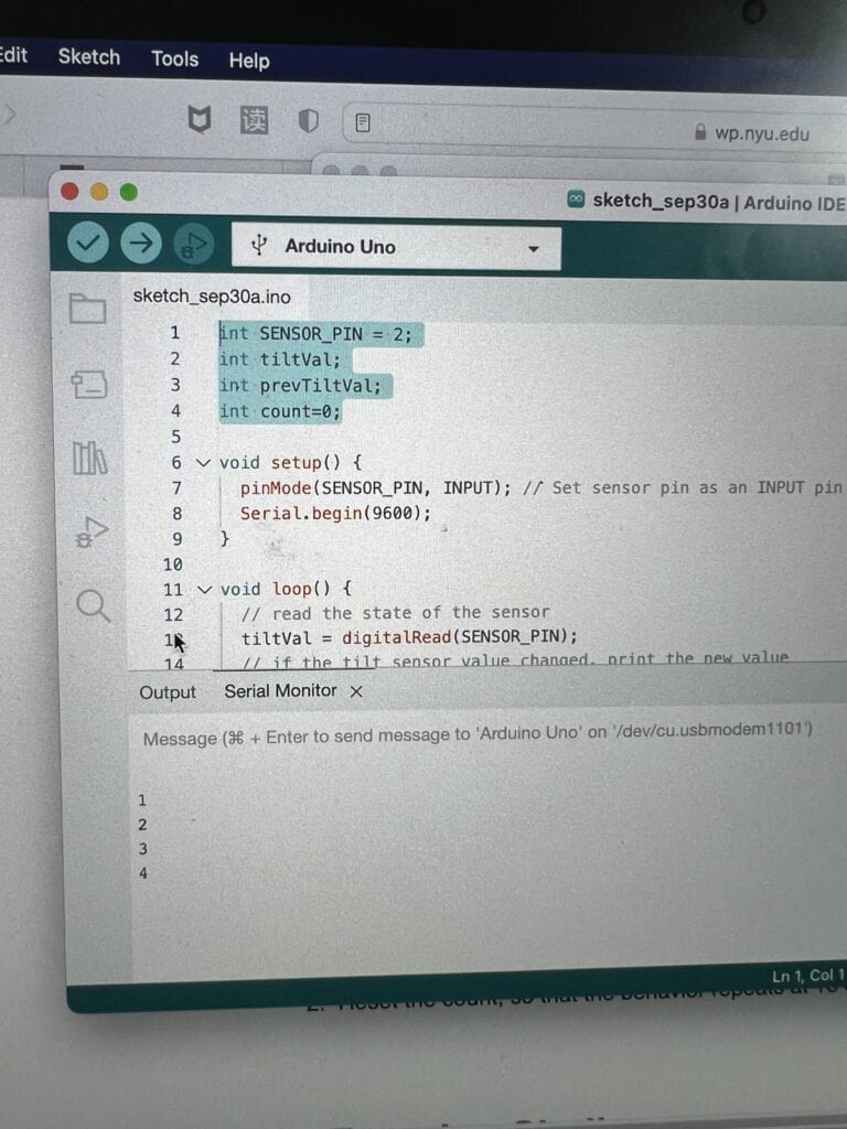
I also wasn’t sure about the global variable. One of the LAs helped me with this too.
Task #3: Set a limit to the variable you are using to count the curls, so that the final code has the following behavior.:
- When the total reaches 8, Print “Yay, you’ve done one set of curls”. Hint: you will need another conditional
- Reset the count, so that the behavior repeats at 16 curls, 24, etc.
int SENSOR_PIN = 2;
int tiltVal;
int prevTiltVal;
int count=0;

void setup() {
  pinMode(SENSOR_PIN, INPUT); // Set sensor pin as an INPUT pin
  Serial.begin(9600);
}

void loop() {
  // read the state of the sensor
  tiltVal = digitalRead(SENSOR_PIN);
  // if the tilt sensor value changed, print the new value
  if (tiltVal != prevTiltVal) {
    if (tiltVal == 1) {
    count=count+1;
    Serial.println(count);
    }
    if (count == 8) {
      Serial.print ("Yay, youve done one set of curls!");
    }
    prevTiltVal = tiltVal;
  }
  delay(10);
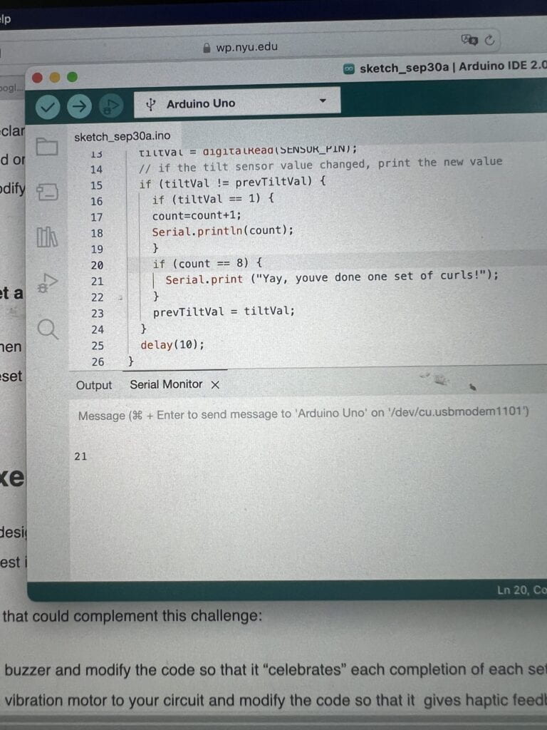
I originally had line 20 as “if tiltval== 8”, but it should be “if count=8.”
Step 5: Exercise challenge
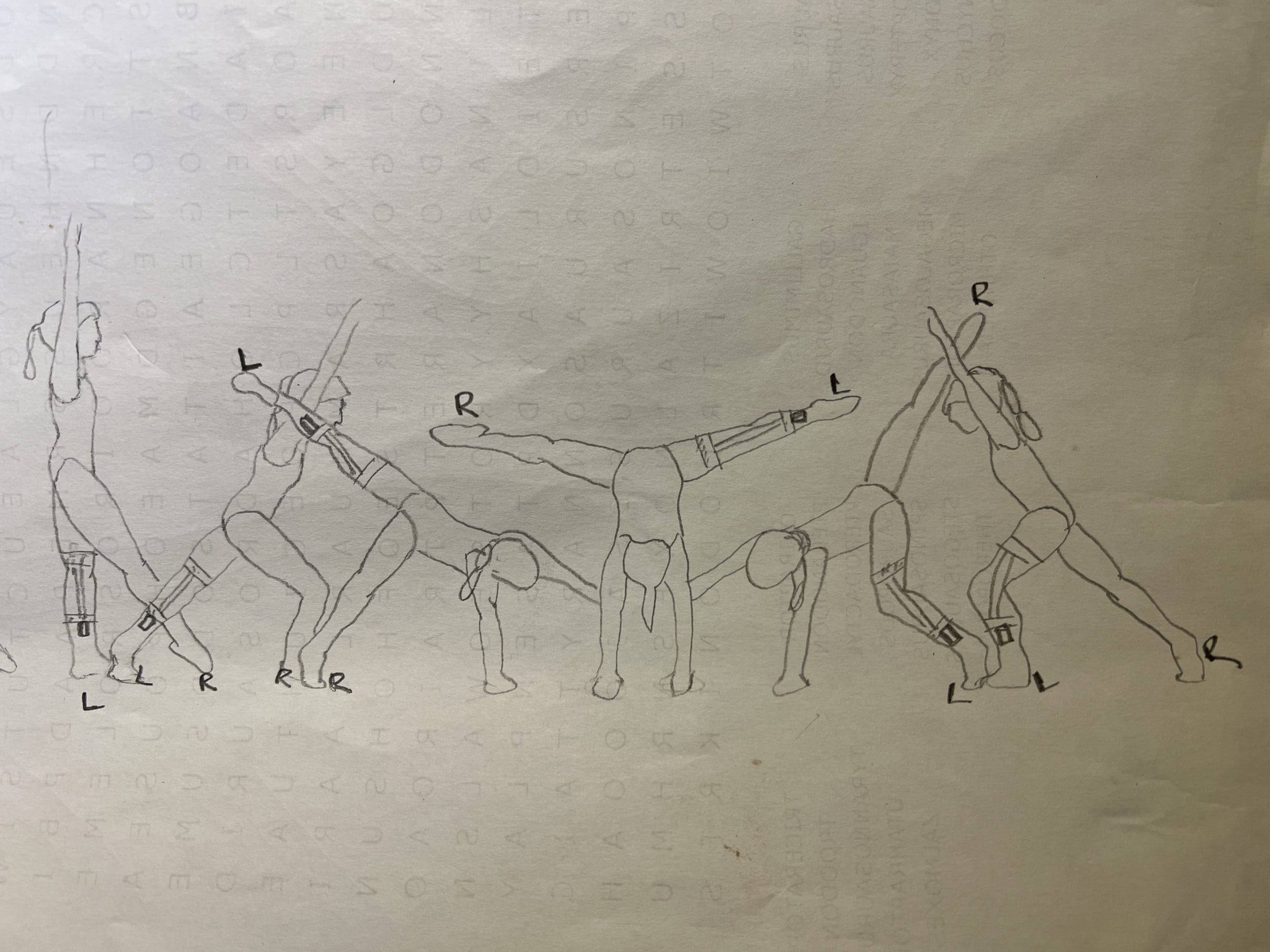
I did not get to this step during recitation, but I’d be curious how the sensor would work if someone were to do a cartwheel. I’m not sure about my theory that the sensor’s tilt angle where it transitions from HIGH to LOW is 180 degrees (vertical angle), and I feel like this movement would be a good way to test that, as a cartwheel involves the body going from a neutral state, to inverted, and back to neutral. You could work with each stage of the cartwheel, ex seeing if the output value changes at the slight angle change from the first to second drawing (standing to lunge), or whether you want to count a full cartwheel. I feel like this is also a good way to use it in a real-world scenario, as this one movement can challenge our design of the sensor, and whether it is accurate enough to deal with the human body’s full range of motion–standing, lunging, flexing, contorting, as well as speed and dynamics.

Documentation
- Record a short video of yourself doing step 4 (bicep curls) and 5 (challenge) while showing the Serial monitor/plotter in action. –>See above videos.
2. Embed your code into your blog as shown with the example codes in this recitation, NOT by taking a screenshot of it. –> See above code.
3. Draw your own illustration sketches that showcase how a person would use this interactive training device.–> see above illustration.
4. Reflect on your experiments, explaining the notes you took, and adding photos, and/or screen shots to document what tests you have tried and what you have learned from them. As a guidance, use the following questions:
-
-
-
-
- At what angle of tilt does it transition between HIGH and LOW?
-
-
- Responding for step 1 and 2: as shown in the video, the number on serial monitor wouldn’t change between 0 and 1 until the sensor reached a vertical (180 degrees) position.
- Responding for step 4: the sensor seemed to be more sensitive (?) when I wore it. It would curiously change values when I was at the top of the bicep curl (fist drawn towards my body, sensor at 180 degrees) and at the bottom of a curl (fist away from my body, sensor lying more or less horizontal on my arm).
-
-
- What else did you notice about its behavior?
- Sometimes the sensor didn’t behave exactly how I wanted it to or expected it to. Like what I mentioned above, for example it might count up before I was done with a full arm movement.
- What if you rotate the limb that has the sensor attached to it?
-
- I’m not sure about this, because based on the above it seems like the sensor counts a value when it goes from (vertical-vertical aka flips over) and (vertical-horizontal). I think if you had it taped horizontally to your arm, and you rotated it inwards so that it goes from horizontal-horizontal (flips over like vertical-vertical), it might also work. I think it’s more likely that the output value will not change though.
-
- What if you shake it?
- The output value would keep fluctuating.
- What if you hold the wires several centimeters away and tilt it?
- Do you think it can be used by any user?
- I think with a little fine-tuning it could be useful for those who like to stay fit and those who want to add more fun and interactivity to staying active.
- At what angle of tilt does it transition between HIGH and LOW?
-
-
-
Recitation 2: Arduino Basics (9.23.22)
In our second recitation, we built three different circuits and ran them with code to practice our use of Arduino. I worked with Stephen to make these.
Circuit 1: Fade
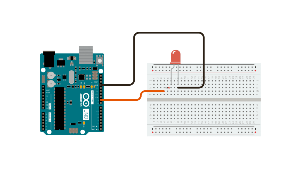
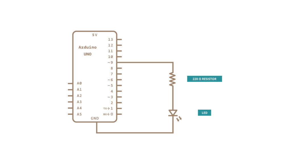
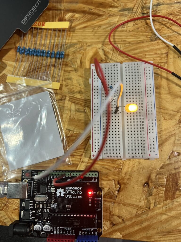
The code for circuit 1. Select from Arduino IDE > File > Examples > 03.Analog > Fading and upload it to your Arduino:
/*
Fade

This example shows how to fade an LED on pin 9 using the analogWrite()
function.

The analogWrite() function uses PWM, so if you want to change the pin you're
using, be sure to use another PWM capable pin. On most Arduino, the PWM pins
are identified with a "~" sign, like ~3, ~5, ~6, ~9, ~10 and ~11.

This example code is in the public domain.

https://www.arduino.cc/en/Tutorial/BuiltInExamples/Fade
*/

int led = 9; // the PWM pin the LED is attached to
int brightness = 0; // how bright the LED is
int fadeAmount = 5; // how many points to fade the LED by

// the setup routine runs once when you press reset:
void setup() {
// declare pin 9 to be an output:
pinMode(led, OUTPUT);
}

// the loop routine runs over and over again forever:
void loop() {
// set the brightness of pin 9:
analogWrite(led, brightness);

// change the brightness for next time through the loop:
brightness = brightness + fadeAmount;

// reverse the direction of the fading at the ends of the fade:
if (brightness <= 0 || brightness >= 255) {
fadeAmount = -fadeAmount;
}
// wait for 30 milliseconds to see the dimming effect
delay(30);
}
This circuit used the analogWrite() function to fade an LED light on and off. I originally made my circuit more complicated than it needed to be. I had the red wire connecting to pin 9, and the black wire connecting to ground, both connecting to extra cables (that had both ends attached to the breadboard) that then connected to the LED. I think I had gotten used to practicing with somewhat more complex circuits, and didn’t think think to follow the schematic exactly as shown until my partner commented that my circuit seemed too busy. The schematic instructed to connect the ground cable directly to the cathode, and the pin 9 cable to the anode through a resistor. After revising the circuit, I uploaded the code, which ran without problems immediately.
Circuit 2: toneMelody
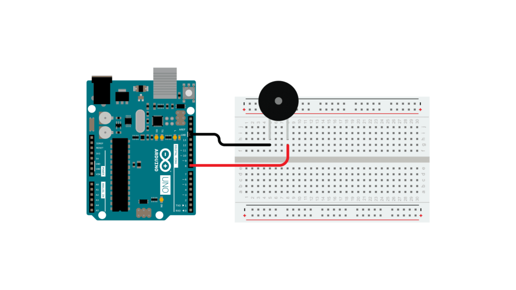
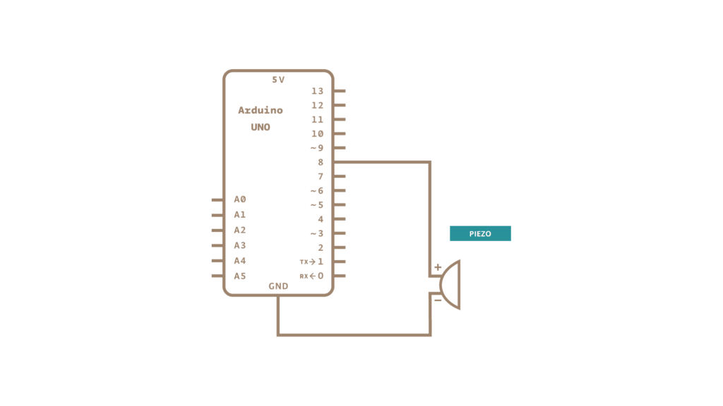
‘
Main code sketch
/*

Melody

Plays a melody

circuit:

- 8 ohm speaker on digital pin 8

created 21 Jan 2010

modified 30 Aug 2011

by Tom Igoe

This example code is in the public domain.

http://www.arduino.cchttps://www.arduino.cc/en/Tutorial/Tone

*/

#include "pitches.h"

// notes in the melody:
int melody[] = {

NOTE_C4, NOTE_G3, NOTE_G3, NOTE_A3, NOTE_G3, 0, NOTE_B3, NOTE_C4
};

// note durations: 4 = quarter note, 8 = eighth note, etc.:
int noteDurations[] = {

4, 8, 8, 4, 4, 4, 4, 4
};

void setup() {

// iterate over the notes of the melody:

for (int thisNote = 0; thisNote < 8; thisNote++) {

// to calculate the note duration, take one second divided by the note type.

//e.g. quarter note = 1000 / 4, eighth note = 1000/8, etc.

int noteDuration = 1000 / noteDurations[thisNote];

tone(8, melody[thisNote], noteDuration);

// to distinguish the notes, set a minimum time between them.

// the note's duration + 30% seems to work well:

int pauseBetweenNotes = noteDuration * 1.30;

delay(pauseBetweenNotes);

// stop the tone playing:

noTone(8);

}
}

void loop() {

// no need to repeat the melody.
}
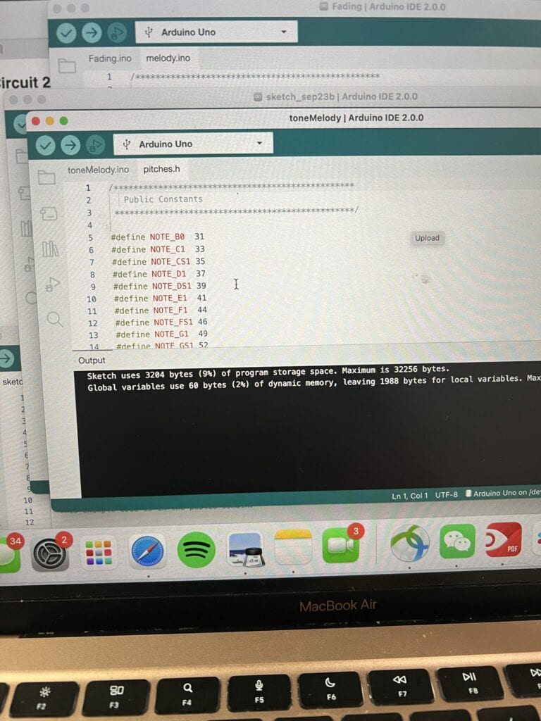
Additional Code. The code for circuit 2. Access the code from Arduino IDE > File > Examples > 02.Digital > toneMelodyand upload it to your Arduino.
/*************************************************

* Public Constants

*************************************************/

#define NOTE_B0 31
#define NOTE_C1 33
#define NOTE_CS1 35
#define NOTE_D1 37
#define NOTE_DS1 39
#define NOTE_E1 41
#define NOTE_F1 44
#define NOTE_FS1 46
#define NOTE_G1 49
#define NOTE_GS1 52
#define NOTE_A1 55
#define NOTE_AS1 58
#define NOTE_B1 62
#define NOTE_C2 65
#define NOTE_CS2 69
#define NOTE_D2 73
#define NOTE_DS2 78
#define NOTE_E2 82
#define NOTE_F2 87
#define NOTE_FS2 93
#define NOTE_G2 98
#define NOTE_GS2 104
#define NOTE_A2 110
#define NOTE_AS2 117
#define NOTE_B2 123
#define NOTE_C3 131
#define NOTE_CS3 139
#define NOTE_D3 147
#define NOTE_DS3 156
#define NOTE_E3 165
#define NOTE_F3 175
#define NOTE_FS3 185
#define NOTE_G3 196
#define NOTE_GS3 208
#define NOTE_A3 220
#define NOTE_AS3 233
#define NOTE_B3 247
#define NOTE_C4 262
#define NOTE_CS4 277
#define NOTE_D4 294
#define NOTE_DS4 311
#define NOTE_E4 330
#define NOTE_F4 349
#define NOTE_FS4 370
#define NOTE_G4 392
#define NOTE_GS4 415
#define NOTE_A4 440
#define NOTE_AS4 466
#define NOTE_B4 494
#define NOTE_C5 523
#define NOTE_CS5 554
#define NOTE_D5 587
#define NOTE_DS5 622
#define NOTE_E5 659
#define NOTE_F5 698
#define NOTE_FS5 740
#define NOTE_G5 784
#define NOTE_GS5 831
#define NOTE_A5 880
#define NOTE_AS5 932
#define NOTE_B5 988
#define NOTE_C6 1047
#define NOTE_CS6 1109
#define NOTE_D6 1175
#define NOTE_DS6 1245
#define NOTE_E6 1319
#define NOTE_F6 1397
#define NOTE_FS6 1480
#define NOTE_G6 1568
#define NOTE_GS6 1661
#define NOTE_A6 1760
#define NOTE_AS6 1865
#define NOTE_B6 1976
#define NOTE_C7 2093
#define NOTE_CS7 2217
#define NOTE_D7 2349
#define NOTE_DS7 2489
#define NOTE_E7 2637
#define NOTE_F7 2794
#define NOTE_FS7 2960
#define NOTE_G7 3136
#define NOTE_GS7 3322
#define NOTE_A7 3520
#define NOTE_AS7 3729
#define NOTE_B7 3951
#define NOTE_C8 4186
#define NOTE_CS8 4435
#define NOTE_D8 4699
#define NOTE_DS8 4978
This circuit used the tone() command to generate notes, which in succession, played a melody.
This circuit was straightforward to build, as it just involved replacing the LED with a buzzer, making sure the positive leg was connected to pin 8 and the negative leg was connected to GND. The resistor was also removed.
At first, the buzzer would sound properly, but I couldn’t get it to sound the melody. I asked an LA for help, and after confirming that my circuit had no issues, she looked at my code. I had only entered the second set of code that defines the notes, and not the first set. After including all of it, the melody played.
Circuit 3: Speed Game
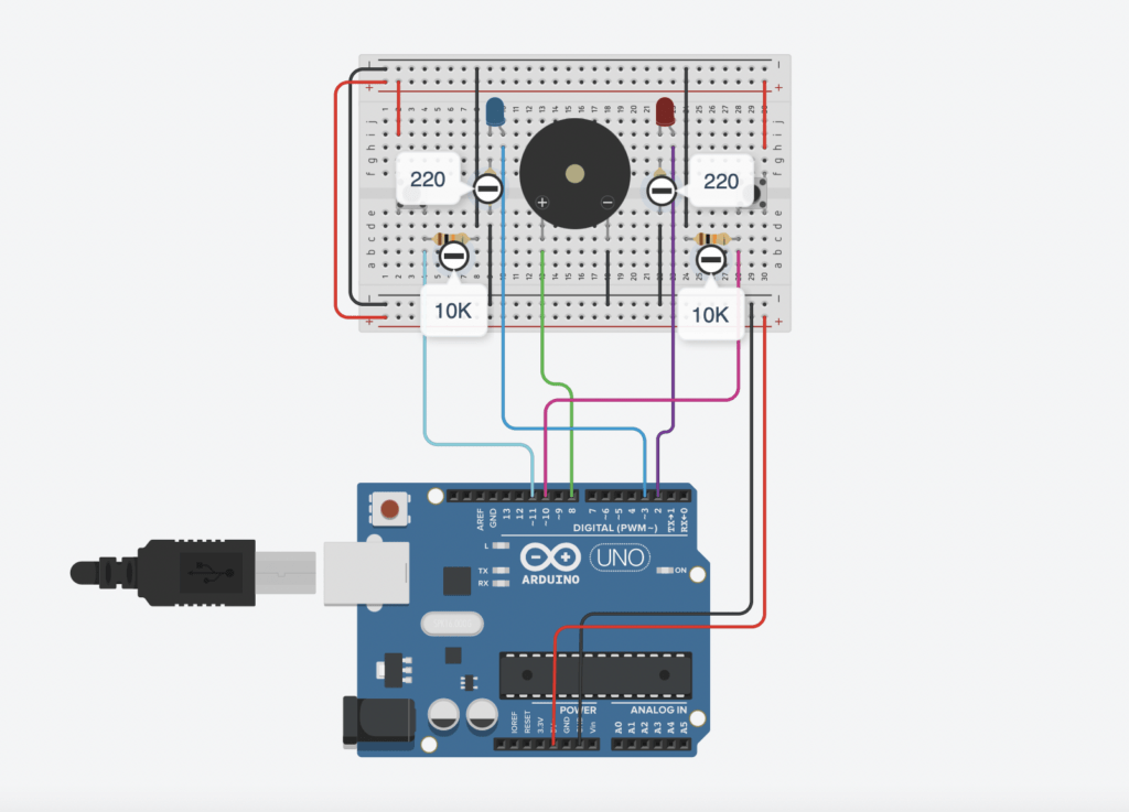
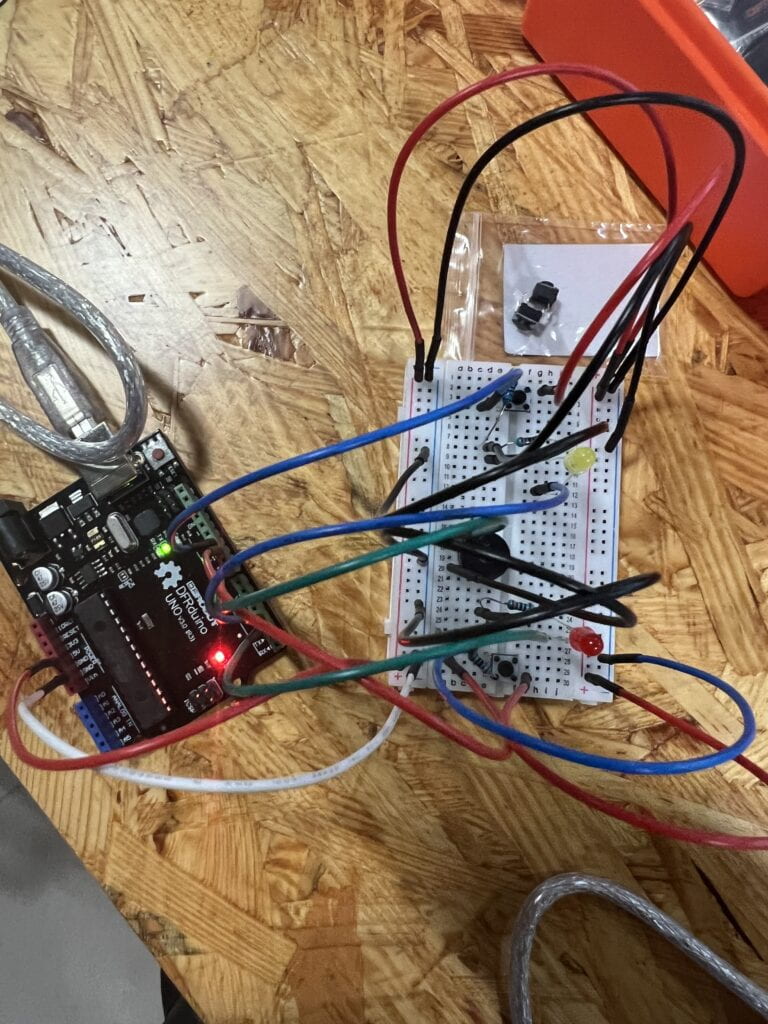
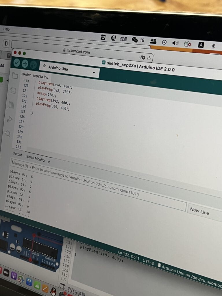
Code:
int buzzerPin = 8;
int button1 = 11;
int button2 = 10;
int led1 = 3;
int led2 = 2;

int goal = 10;
int buttonState1 = LOW;
int previousState1 = LOW;
int buttonState2 = LOW;
int previousState2 = LOW;

int counter1 = 0;
int counter2 = 0;
boolean winner1 = false;
boolean winner2 = false;

// the follow variables are long's because the time, measured in miliseconds,
// will quickly become a bigger number than can be stored in an int.
long time = 0; // the last time the output pin was toggled
long debounce = 200; // the debounce time, increase if the output flickers

void setup() {
// put your setup code here, to run once:
Serial.begin(9600);
pinMode(buzzerPin, OUTPUT);
pinMode(button1, INPUT);
pinMode(button2, INPUT);
pinMode(led1, OUTPUT);
pinMode(led2, OUTPUT);
Serial.println("******************* RACE THE LED *******************");
delay(1000);
Serial.println("READY");
delay(1000);
Serial.println("SET");
delay(1500);
Serial.println("GO!!!!!!!!!!!!!!!!");

}

void loop() {
// put your main code here, to run repeatedly:
buttonState1 = digitalRead(button1);
buttonState2 = digitalRead(button2);
//Serial.println(buttonState1);

//this checks the times player 01 has pressed the button
if (counter1 < goal && winner2 == false) {
if (buttonState1 != previousState1 && millis() - time > debounce) {
if (buttonState1 == HIGH) {
counter1++;
Serial.print("player 01: ");
Serial.println(counter1);
time = millis();
}
}
previousState1 = buttonState1;
if (counter1 == goal && winner2 == false) {
winner1 = true;
digitalWrite(led1, HIGH);
Serial.println("PLAYER 01 WINS");
playMelody();
}
}

//this checks the times player 02 has pressed the button

if (counter2 < goal && winner1 == false) {
if (buttonState2 != previousState2 && millis() - time > debounce) {
if (buttonState2 == HIGH) {
counter2++;
Serial.print("player 02: ");
Serial.println(counter2);
time = millis();
}
}
previousState2 = buttonState2;
if (counter2 == goal && winner2 == false) {
winner2 = true;
digitalWrite(led2, HIGH);
Serial.println("PLAYER 02 WINS");
playMelody();
}
}

}

void playFreq(double freqHz, int durationMs) {
//Calculate the period in microseconds
int periodMicro = int((1 / freqHz) * 1000000);
int halfPeriod = periodMicro / 2;

//store start time
long startTime = millis();

//(millis() - startTime) is elapsed play time
while ((millis() - startTime) < durationMs) {
digitalWrite(buzzerPin, HIGH);
delayMicroseconds(halfPeriod);
digitalWrite(buzzerPin, LOW);
delayMicroseconds(halfPeriod);
}
}

void playMelody() {

playFreq(262, 100);
playFreq(294, 100);
playFreq(349, 100);
playFreq(294, 100);
playFreq(440, 200);
delay(100);
playFreq(440, 400);
playFreq(392, 400);
delay(300);
playFreq(262, 100);
playFreq(294, 100);
playFreq(349, 100);
playFreq(294, 100);
playFreq(392, 200);
delay(100);
playFreq(392, 400);
playFreq(349, 400);

}
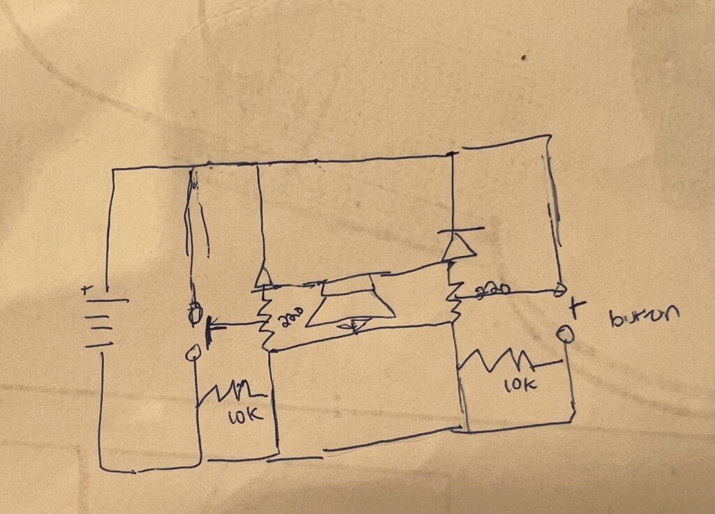
This circuit, when finished, is a two-player speed game where you race to click the button a total of 10 times, and faster than your partner. If you win, your LED flashes. I think this is my favorite circuit we’ve made so far.
We built the circuit using my equipment and following the diagram on TinkerCAD. I think I’m the type of person to be meticulous and worried that something bad will happen if I don’t follow instructions or a diagram completely, but Stephen said we didn’t need to follow the diagram completely (when it came to certain placements, like placement of some wires). We worked from left to right, adding to the circuit starting from the left hand side of the diagram and ending with the right. This circuit is mostly symmetrical, sort of like any two-player game platform like a ping pong table or tennis court. The basic structure of this circuit is: buzzer in the center across the two ravines, and one LED and button per person connected to power through a resistor and wire.
We connected the finish circuit and uploaded the code in TinkerCAD into Arduino. I found it really cool to see the game pop up in the serial monitor. I was relieved and surprised that we got it to work on the first try. Stephen won the first time and I won the second time. We unfortunately didn’t have time to try using the DIY paddles or combining the circuit with another team.
I can’t remember, but I think we made a mistake by not using two 10 k Ohm resistors, only four 220 ones.
Reflection
Q1: Propose another kind of creative button you could use in Circuit 3 to make the game more interactive. Read and use some material from the Physical Computing, Introduction Chapter (p. xvii – p. xxix) to explain why this button would make this game more interactive.
The quotations on how we can still use computers a medium for expression to its full potential resonated with me. Tom Igor and Dan Sullivan offer that “we need to think about
computers that sense more of your body, serve you in more places, and convey physical expression in addition to information” (16). I think something like making a button pad, where the person has to jump 10 times as fast as they could, could be even more fun and challenging. Another alternative would be a weight sensitive jump pad, where a level of force has to be reached. Something that might be harder to conceive is a device that can sense subtle changes in pitch, and the person who sings the highest or lowest note wins. The authors also write how intent is important to imagination–“we need to decide why it [the computer needs to take new forms. We need to take a better look at ourselves to see our full range of expression. This includes everything from the spontaneous expression on your face to the more deliberate
expression of a trained artist… humans have amazing abilities
for reading into this body language the interior state of another person” (19). I think this is an important mindset to have, and a mindset that can allow the creation of activities more accessible and that can provide joy to more groups of people, like those who might not be physically able to press a button.
Q2: Why did we use a 10 kOhm resistor with each push button?
This type of resistor is a variable resistor. 10k ohm refers to its resistance. A 10k resistor is important in acting as a pull up/down resistor for the switch. When the switch is open, the resistor connects the pin to the ground, so it reads LOW when there is no voltage flowing through, and HIGH when there is. This keeps the pin in a known state. With the 220 resistor, there is a stronger current flowing from power to ground, so the LED might blow up.
Q3: In the book Getting Started with Arduino there is a clear description about the “Arduino Way” in chapter 2. Find a project that you find interesting that can be used as an example for these kind of projects. Cite it in adequate manner, include a picture, and explain the reasons that you chose it.
The “Arduino Way” is getting comfortable in getting lost and engineering something in an unconventional way.
"I have always been fascinated by modularity and the ability to build complex systems by connect- ing together simple devices. This process is very well represented by Robert Moog and his ana- logue synthesizers. Musicians constructed sounds, trying endless combinations by patch- ing together different modules with cables. This approach made the synthesizer look like an old telephone switch, but combined with the numerous knobs, that was the perfect platform for tinkering with sound and innovating music. Moog described it as a process between “wit- nessing and discovering”. I’m sure most musi- cians at first didn’t know what all those hun- dreds of knobs did, but they tried and tried, refining their own style with no interruptions in the flow" (Banzi, 7).

—Massimo
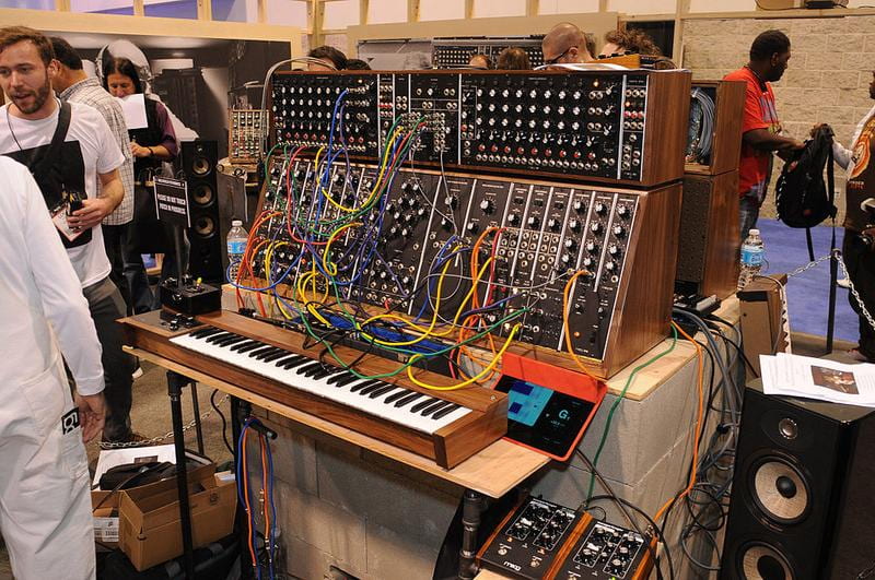
This quote stood out to me. What if we could replicate something like this, where not only professionals and creatives contribute to it, but also amateurs and regular people? The result would be something that has the identity of many people, who also have the challenge of making it cohesive in the end.
Group Research Project: Read
The Ones Who Walk Away From Omelas by Ursula Le Guin

I think what’s challenging about imagining an interactive artifact for the city within this story, is considering that interactivity should be planned and geared towards a general goal. What is my intent here after reading this? I think this story aligns with civilization and resembles many societies today. There is truth in saying that, it is through discovery, knowledge, and convincing oneself of something, that atrocities are justified. Is the goal to bring the citizens out of their apathy? And for what reason–to incite them to rebel, or at least, be aware and uncomfortable as they live?
My initial idea was a type of display in an area of the city with lots of traffic, such as a glass tube where orbs or balls would be added for each person that leaves the Omelas. While possibly impactful and revelatory to look at, I struggled to think how it would be interactive. Maybe, citizens could select an orb, and the display could project a quote or the voice of who left and why they left.
Another idea is an immersive device, like a viewfinder toy, or a display case in the town center, to those who don’t want to actually visit the child. The conditions of the child could be replicated, like what the child sees, smells, feels, and thinks. To help Omelas citizens feel more directly attached, there could be visualizations of their own children or family members in the situation of the child (this would be psychologically abusive though). The display case could also be an escape room type of activity, which changes in layout for each person who tries, so it remains unpredictable. I imagine there could also be an issue with these ideas being used for voyeuristic purposes.
The Plague by Yan Leisheng
I think one point of exigence here, is how to let the general population know that these individuals are alive. I would utilize the null gravity channels, where someone from the inside, maybe a worker who stayed on but who shares the same morality as the narrator, can send coded messages out through food packages. Security personnel that then go out into the regions can see messages in the same alphabet on the signs in the places they drop by, denoting whether or not the people there have received the communication, and if there is a plan. The language here would be interactive.–couldn’t really think of anything for this story…
The Veldt by Ray Bradbury
This story raises concerns on the overreliance of technology and how relationships can fall into disrepair because of it. I think it’s altogether possible that the parents in this story have forgotten how to do some basic things, due to the house that “clothed and fed and rocked them to sleep and played and sang and was good to them” (Bradbury, 1). I would design a studio of sorts, one that could flip between rooms like a kitchen, laundry room, and bedroom. Each room would be furnished with the requisite utilities. There could be tutorials or a robot “helping hand” that can help the parents relearn a more normal way of living, and provide inference on how it could be more beneficial than the technologically advanced way of doing things they are used to. This setting should be dynamic and learn from the areas the parents struggle in, or excel in, to change difficulty settings and have them “level up.” It’s also possible the children were raised with an atypical setting of nurture. I would see the benefit in this setting being, the parents being able to introduce to their children a natural way of conveying care and love, and not the artificial way of something like the house tucking the children into bed.
How Do I Define Interaction? (Group Research Project: Research)
After interacting with the readings and the authors that penned them, as well as learning about a few of the interactive artworks out there, I would come to define interaction similarly to Chris Crawford’s definition, which is a cyclic, mutual process that involves an exchange of information and action through listening (input), thinking (process) and speaking (output). I would add onto this definition, with inspiration from Zach Lieberman, and define interaction as fluid–unable to be defined fully by the artist, who can set the context of their piece, but not dictate how an audience will interact with it, and unable to be predicted by the audience, for a unique response should be produced based on each unique individual. To me, ideal interactivity is achieved when a work not only meets but exceeds the basic foundations of Crawford’s “conversation.” and functions not as a static or predictable work that responds uniformly, but as a dynamic piece that is willing to and does work with the user to produce unique results.
I previously failed to really consider interaction being much beyond my basic understanding of the word, which is just any kind of action or communication effected on, or attempted, another object or individual. However, I think a distinction interaction has is that it has to feature intention.
Reading “What Exactly Is Interactivity” by Chris Crawford made me challenge this initial thought and further build on this basic understanding, and realize why it is important to do so. Crawford states his belief of interactivity being akin to a conversation, and a conversation by design needs to meet certain conditions: there must be something said, and a response to what was said. Take for example, a mother that was speaking to a child, but the child was neither actively listening nor making eye contact with her. If you asked me if that mother interacted with her child, I would’ve said yes. I would see interaction, or an attempt on it at least, completed on her part. It is not the fault of one of the actors if the other is not cooperative. However, using Crawford’s definition of degrees of interactivity, I would still assign this exchange a low degree.
Thinking from a design point of view makes me reconsider this. If a participant were to push a button on an installation that doesn’t work as it should, I wouldn’t consider this an interaction at all.
It Is Interactive
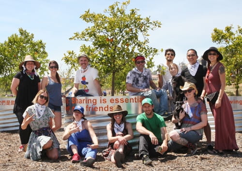

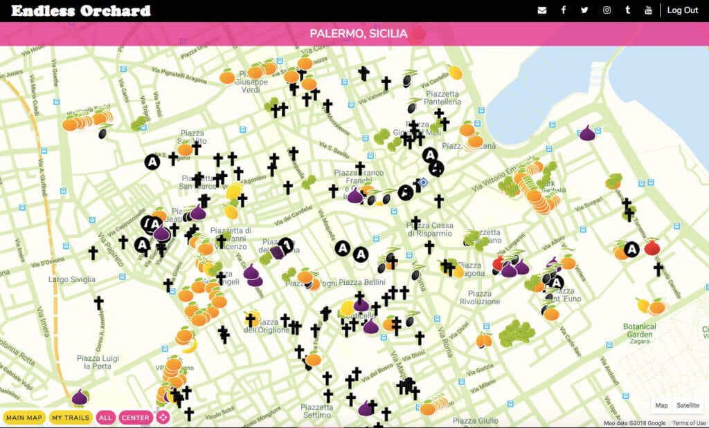
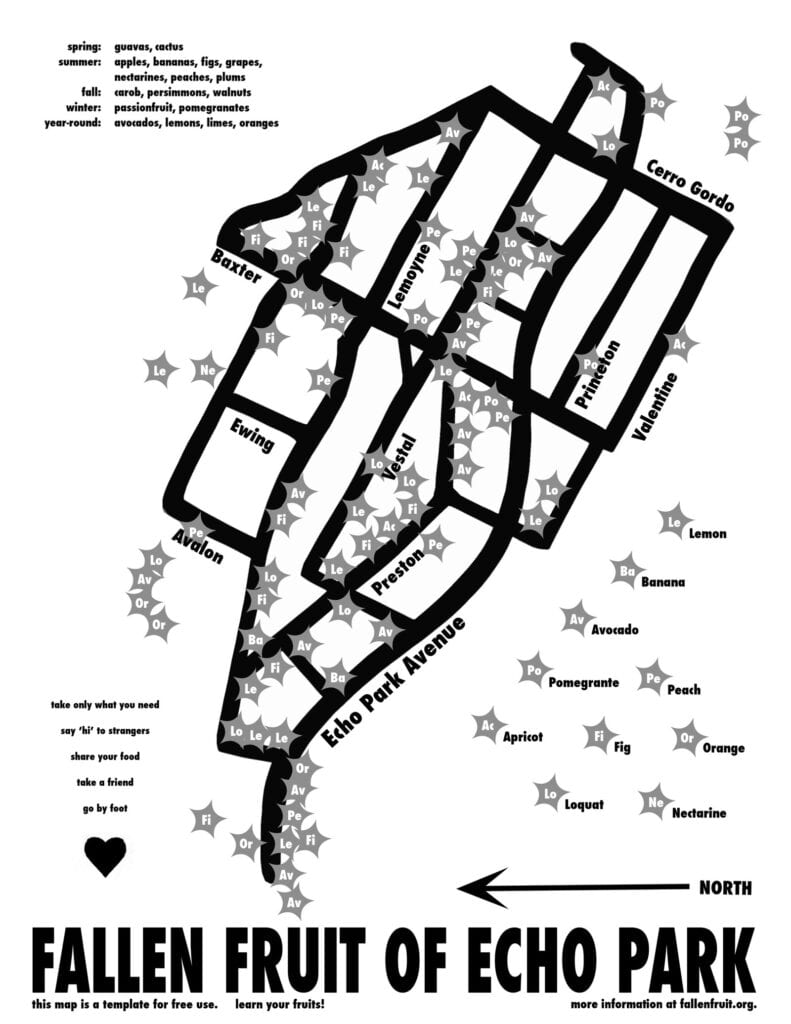

Artist Rikrit Tiravanija, sees all the value, which I understand to be as the “context” of your art as laid out by Tom Igoe’s “Making Interactive Art: Set The Stage, Then Shut Up and Listen”, in space. He provides participants with the means to interact with his art, describing it as “mediators between the audience and the artist” (Lee). He uses “material objects as an interface for social connection” (Lee). Reading this is allowed me to see the interactive side and artistic side of the Fallen Fruit initiative and its Endless Orchard Project. Fallen Fruit plants fruit trees in public spaces for everyone to enjoy; these trees are then mapped and able to be searched. Other regular activities include–and are all communal– picking fruit under moonlight, canning and making jam, fruit tours and meditations, fruit tree adoptions, and making and enjoying multimedia together. I normally wouldn’t ‘t conceive all of this as art, and would have trouble seeing past what seem just like actions of picking fruit, and other activities. But reading about this, I am aware of how new and beautiful something like this to me. It is an interaction between the aesthetic of fruit, an awareness of boundaries and difficulties of living, and parallels between artists crossing boundaries and Fallen Fruit’s fruit trees sometimes on the edge of private property.
Another project I want to introduce is a project I think of from time to time: The Signature Project. The Signature Project is an ongoing work by Patrick Dunning, who presented at my middle school years ago. Its achievement of interactivity may be thanks to the sheer scope of it–apart from the digital mural made of (300,000 and counting) signatures that is its foundation, The Signature Project is a multimedia effort combining digital design, live theater, music, science, humanities, and technology. Apart from signing your name, you are open to share your life story or any moment from your life. The many bodies and minds of Dunning’s dancers, storytellers, musicians, artists, and other crew are also active participants. Like Rirkrit Tiravanija’s approach, this project depends on the participation of people, who completely make and change the fabric of the mural and subsequent performances and content. Dunning himself commented that the mural is something he’s “creating by collaborating with over one million people (Calhoon).” What’s remarkable about this, is that while some artists only make tweaks to essentially finished works to keep them running, or they may even be programmed in doing so without the artist’s reinvolvement, Dunning will always be conversing with his participants and his art. “THE SIGNATURE PROJECT offers me countless ways to create images and elements that find their way into either the performance or the painting itself. There’s no end to the possibilities for me,” Dunning states to Visible Soul writer Zack Calhoon. Additionally, while he opens the experience stating his vision for the project: that it will allow participants to visualize unity with those living different lives than them, he doesn’t tell participants what to take away or what to give him.
It Is Not Interactive

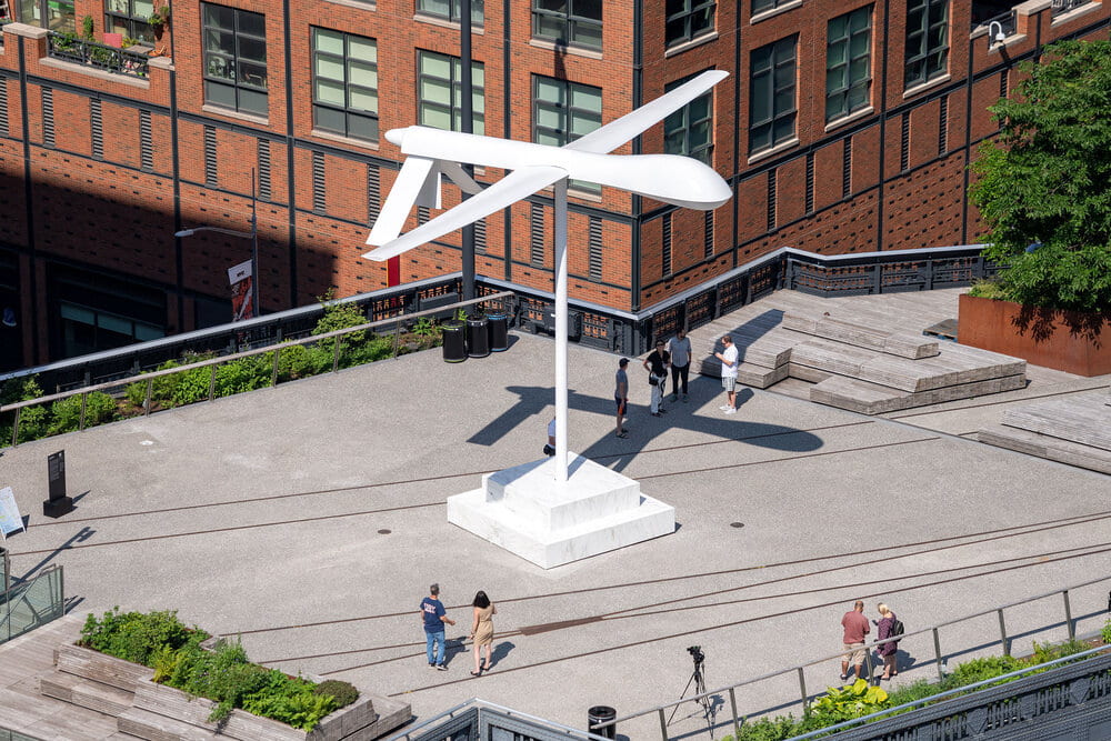
A work I would not consider to be interactive is. Untitled (drone), 2021 by Sam Durant, which is a replica of the General Atomics MQ-1 Predator drone that carried out devastating and targeted killings in the Middle East. Hovering over the NYC High Line, its interactive experience is described by the artist to lie in the base at the bottom of the sculpture that people can sit on and have a conversation on. I would consider this work to likely be very striking and solemn when seen in person, but wouldn’t say it qualifies as interactive. It may drive conversation between people about it, but there is no such reciprocal interaction with the sculpture.
Is it Interactive?
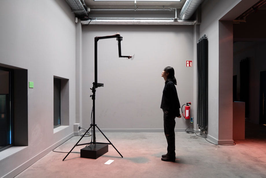
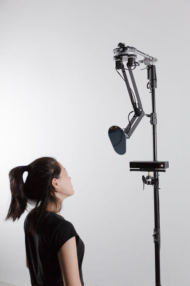
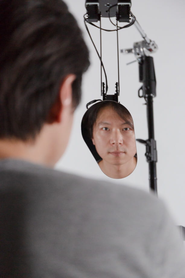
Something I am unsure about is Encounter (2018) by Piet Schmidt, which is a robotic arm with a mirror that observes (input), identifies (process), and reacts (output) to its surroundings, ending up playing with visitors by angling the mirrors towards them. The robot checks the box of producing varied responses, as it is mentioned to have head tracking. I like where it goes with seemingly being imparted with the animal instinct of curiosity, as it is said that “when an unknown person approaches it fearfully retracts but if the person moves away again, it follows curiously” (Visnjic) and that it needs time to get used to a visitor. It is not mentioned however, if there is facial recognition, so I’m not sure if the results can be described as shaped to each person or not. This work ultimately raises more questions: is predictability a killer of interactivity? It may be a fault of the relative simplicity here: as this is only one robotic arm with a mirror. Would people get bored of this as they would with pushing a button on a breadboard to light up an LED over and over again? Also, is the artist sometimes too idealistic? That’s what I thought when I read Schmidt’s use of the words “fearfully” and “curiously” to describe how the machine moves, but this seemed to have been his intention. He writes how its an examination of the dichotomy between our mind and intuitive perception: our mind “realizes that we are dealing with an inevitably lifeless machine” (Schmidt). However, our intuition “perceives a lifelike creature that’s close to us and a social relationship forms” (Schmidt). The robotic arm lunging back might be read as “fearfully” to us as we attempt to make sense of what we are interacting with. Schmidt questions, Do we want increasingly anthropomorphic devices? I think this is an interesting area to explore.
Resources
Crawford, Chris. “What Exactly is Interactivity?” Chris Crawford on Interactive Storytelling, 2nd edition, New Riders, 2012, pp. 1, 5-6.
Igoe, Tom. Making Interactive Art: Set the Stage, Then Shut Up and Listen. (2012, Aug 21). Retrieved September 26, 2022, from https://www.tigoe.com/blog/category/physicalcomputing/405/.
Lee, Patina. How Does Interactive Art Create Meaning? Widewalls. (2016, Aug 16). Retrieved September 26, 2022, from https://www.widewalls.ch/magazine/interactive-art-meaning.
Buckley, Annie. Fallen Fruit. Art in America by Art News. (2009, Oct 22). Retrieved September 26, 2022, from https://www.artnews.com/art-in-america/aia-reviews/fallen-fruit-60371/.
Fallen Fruit. Retrieved September 26, 2022, from https://austinyoung.com/fallenfruit
Fallen Fruit. Curry Stone Foundation. (2018, May 22). Retrieved September 26, 2022, from https://currystonefoundation.org/practice/fallen-fruit/
Teplitzky, Alex. Fallen Fruit Celebrate Their Endless Orchard in Los Angeles. (2021, Nov 9). Creative Capital. Retrieved September 26, 2022, from https://creative-capital.org/2021/11/09/fallen-fruit-celebrate-their-endless-orchard-in-los-angeles/
Calhoon, Zack. The Musings and Diatribes of a New York Actor and Playwright. Visible Soul. (2018, Mar 5). Retrieved September 26, 2022, from https://www.signatureproject.com/off-broadway-reviews.html.
Sam Durant drone set to Grace New York’s high line. The online edition of Artforum International Magazine. (2021, April 15). Retrieved September 26, 2022, from https://www.artforum.com/news/sam-durant-drone-set-to-grace-new-york-s-high-line-85467
Visnjic, Filip. Encounter – suspiciously curious robotics. CreativeApplications.Net. (2020, Sep 29). Retrieved September 26, 2022, from https://www.creativeapplications.net/openframeworks/encounter-suspiciously-curious-robotics/
Encounter. Piet Schmidt. Retrieved Sptember 26, 2022 from https://pietschmidt.de/encounter.html


