Task 1: Build the circuits
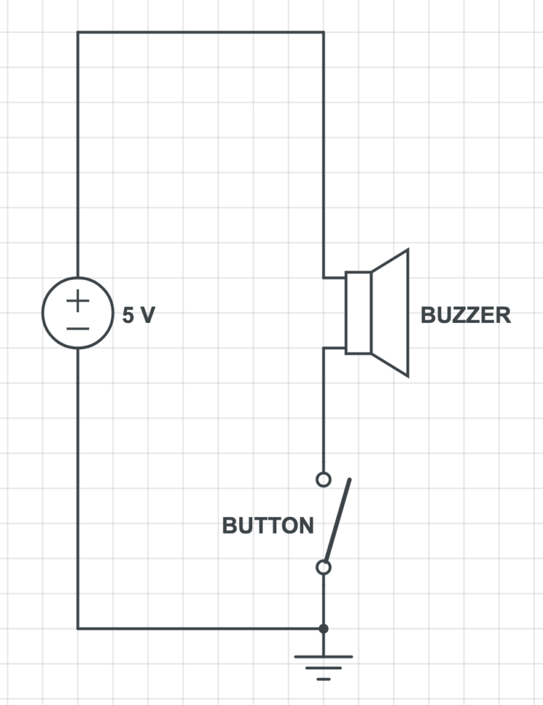
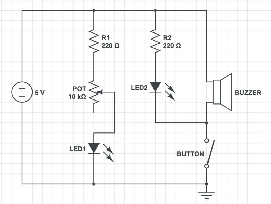
Step 1- We already got a little confused by the diagram here. Personally, I was picturing the flat battery we had used in the second class, but realized we were to use the power supply.
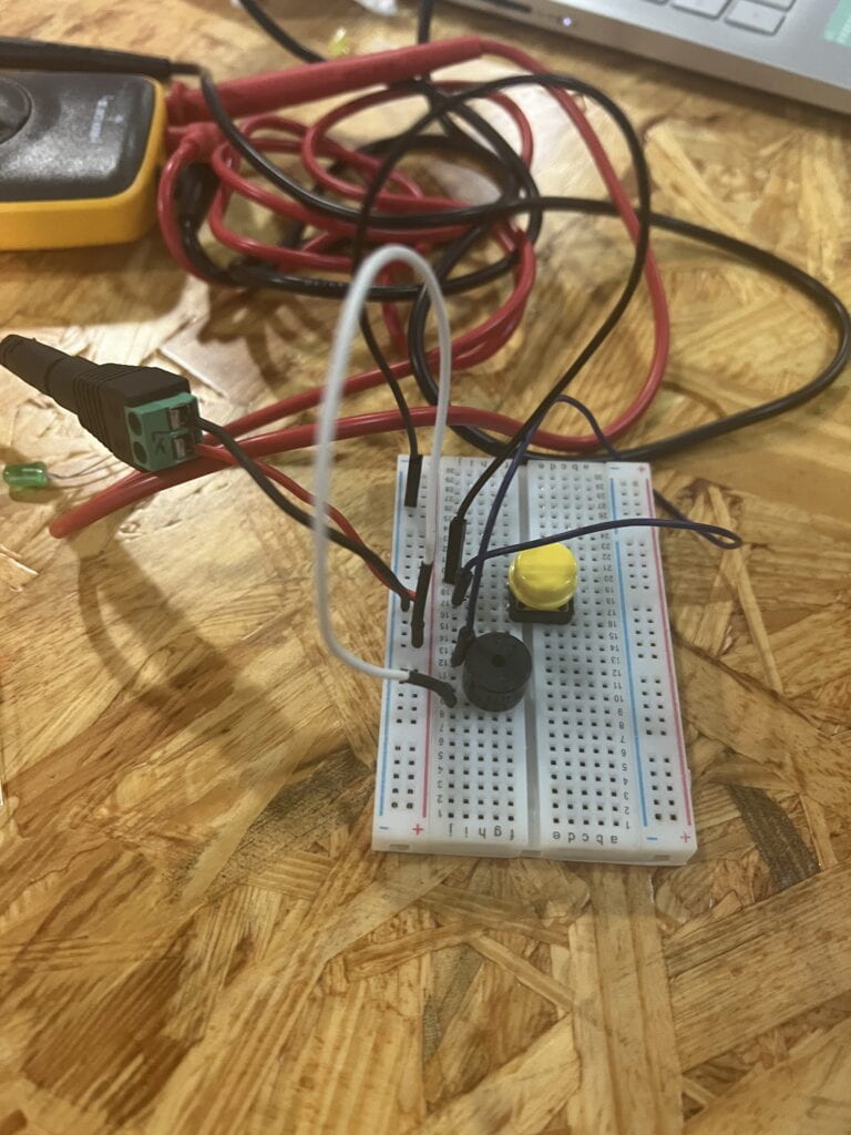
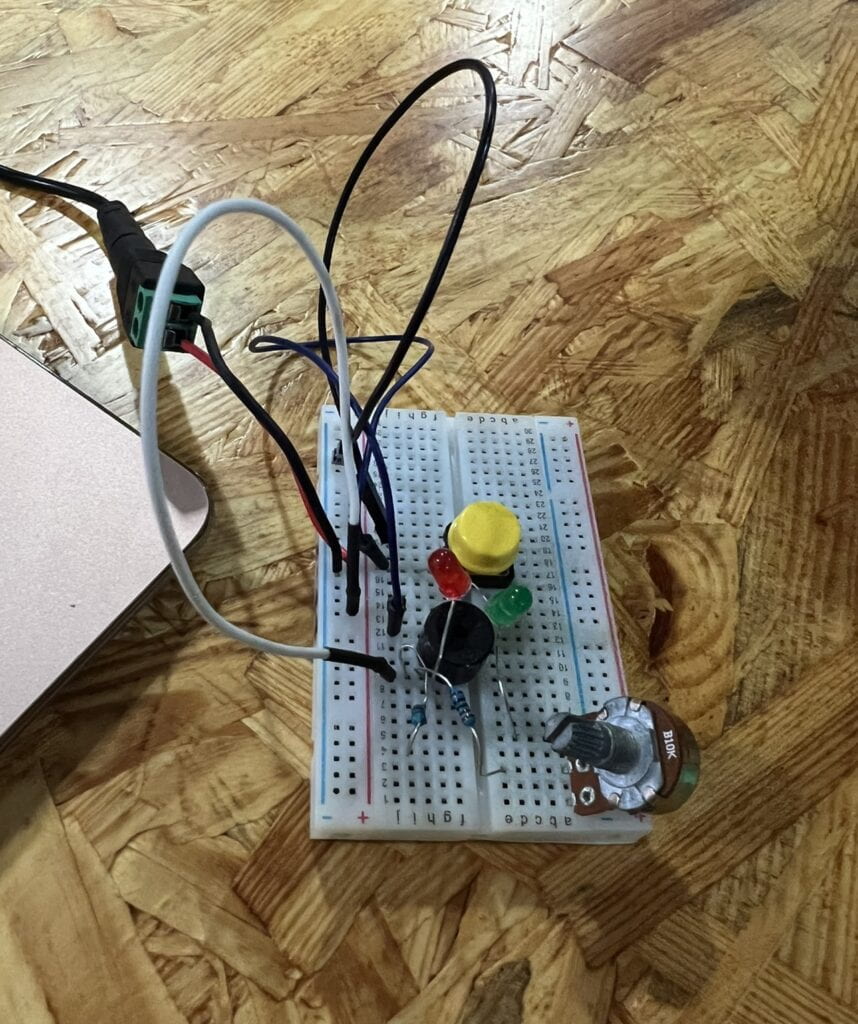
We attached the power source to the breadboard, and then the jumper cables, then buzzer, then the button.
An electric current always flows from positive (area of higher potential energy) to negative (lower potential energy). On the lefthand column, one wire was connected to the positive rail, and one wire was connected to the negative rail. A jumper cable (white) was connected from the positive rail to the same row as one of the legs of the buzzer. Another cable was connected from the negative rail to the left column of the middle section of the board. A third cable was then arranged so that one end was next to the end of the previous cable, and the other next to a leg of the buzzer. The buzzer was placed across the two sections.
The recitation moved quicker than we expected, so we got caught up in working and forgot to closely document what troubleshooting we did. I think we succeeded in getting the button to control the buzzer pretty quickly, though.
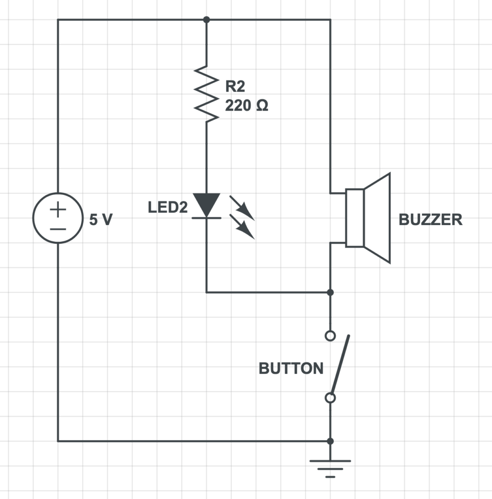
Step 2- We added an LED light and a 220 ohm resistor. I remember that in this step, we ran into an issue where the LED and buzzer were not connected to the button simultaneously–when we pushed the button, only the buzzer would buzz, the LED wouldn’t light up.
Again, because we didn’t document closely, I can’t remember how we went about troubleshooting this. This was an issue with how the LED was connected to power and the button, though.
Step 3- Here, we added a second LED light, another 220 ohm Resistor, and a 10k ohm Variable Resistor (Potentiometer)
Task 2: Build a switch
To build the switch, we went to the studio next door, where Prof. Rudi showed us how to assemble it using 2 squares of cardboard, 2 strips of copper tape, a few strips of masking tape, 2 long wires, and solder. My partner and I each took one square of cardboard, where we attached a strip of copper tape to one end and folded it over. We prepared one long wire each by using the tool to strip about 1cm of insulation coating off of one end, exposing the metal. We used masking tape to secure this wire to the cardboard at an angle in a way that allowed the exposed metal to lay on top of the copper tape. To secure it, we used the soldering iron and solder to bond the metal end to the tape. We then used masking tape to tape the squares of cardboard together at one end to form a ‘V’ shape.
I’m not sure about my partner, but this is my first time ever using a soldering iron. Prof. Rudi pointed out how we hold it like a pen, but unlike a pen, we don’t use the (very small) tip of the iron. Instead, it works best being held at an angle–but controlling it is harder than it looks. At first, we struggled a little in getting the solder to pool on top of the wire. You have to use the tool to sort of “cut” the solder, and then hold the iron against it for awhile and let the temperature cause it to heat up more and eventually pool.
Task 3: Switch the switches and send a message
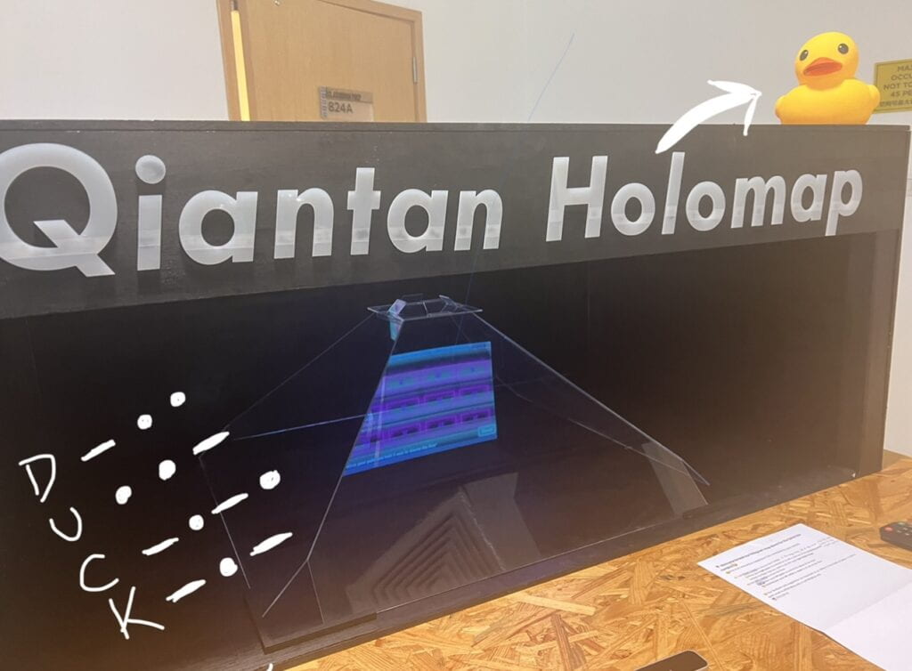
Replacing the push button with the paddle switch was straightforward–attaching the two ends of the two wires to the breadboard where the push button was–and produced amusing results. When open in a ‘V’ shape, the buzzer wouldn’t buzz. When folded so the conductive copper tape strips touched, it would buzz. My partner and I sent the message ‘DUCK’ (inspiration of which came from the rubber duck in the 825 studio). We tried to quiz each other, but quickly gave up as you would probably have to either memorize the alphabet in morse code to quickly decode it. We still found this type of interaction, where we could hold the switch in our hands and press it closed, more fun than just pushing a button with our finger.
The physical position of the switch: when “closed” (buzzer sounds) the current can flow from one contact to another. When “open” (buzzer does not sound) no current can flow between contacts
