CONCEPTION AND DESIGN
Our project, “EDM Experience,” was conceived out of a shared passion for EDM music and live performances, a sentiment shared by my partner, Tammy Huang, and me. Our project concept was to create an engaging and immersive experience that allows users to explore the experience of Electronic Dance Music (EDM) through a combination of sound and visuals. We want to take inspiration from the full experience of a rave and create an accessible, but also user-friendly EDM soundboard that lets music enthusiasts experiment with different sounds, rhythms, beats and light shows.
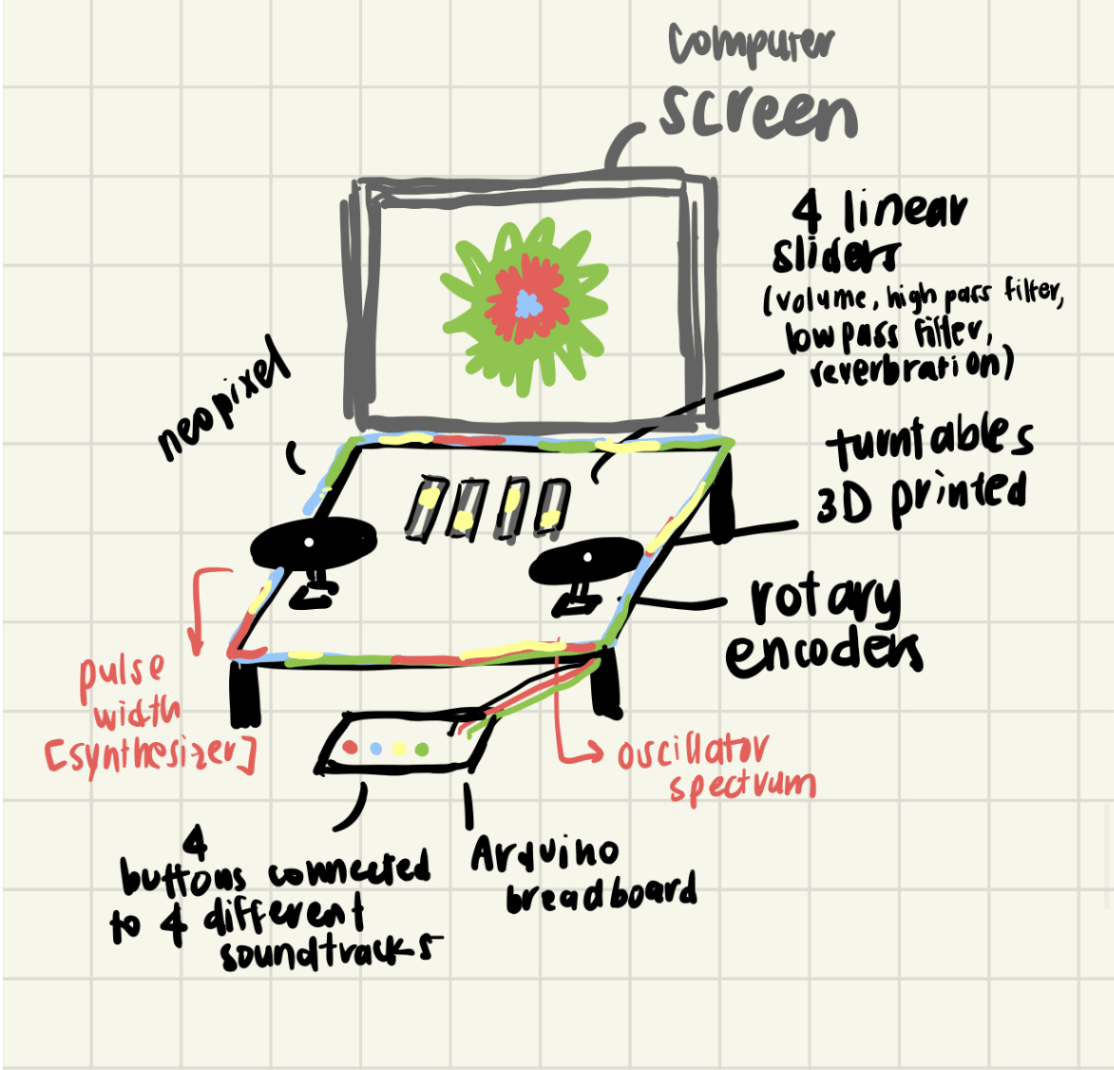
[PHOTO: our original brainstorm sketch]
Our preparatory research, especially into beginner DJ equipment, played a pivotal role in shaping our project. This research not only offered valuable insights into the aesthetic aspects but also served as a practical guide during the design and construction phases. By closely examining the design inspirations and actual constructions in our research, we gained a clearer understanding of the visual and structural elements that make a DJ setup appealing.
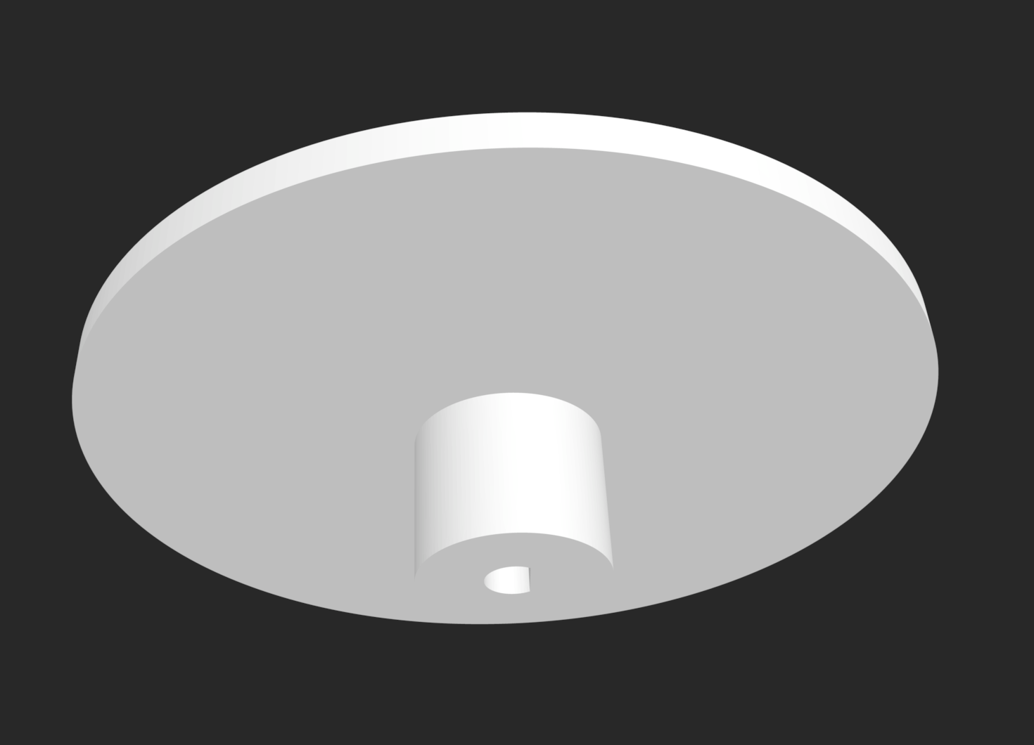
Understanding how users would interact with our project informed key design decisions. Our goal was to simplify the complex tools used in music and production studios. We modified the purposes of different components until they aligned with our objectives. The final design incorporated two rotary encoders with 3D printed circular turntables, mimicking the tactile experience of real DJs. These served as key sensors controlling the speed/frequency and time position of the song. Three buttons played short one-second sounds, and four sliders controlled the volume of distinct sound stems – vocals, guitar, drums, and backing track. A neopixel strip lined the soundboard, coordinating with the music through amplitude analysis, creating a visually dynamic and immersive experience.
Throughout the project, we made numerous changes based on user feedback, particularly from the User Testing Session. One notable adjustment was increasing the sensitivity of the rotary encoder turntables to better reflect adjustments in the music. Although the slider potentiometers were initially non-functional, user testing prompted suggestions for alternative purposes. We took this feedback, and made many improvements to our project design to enhance user satisfaction.
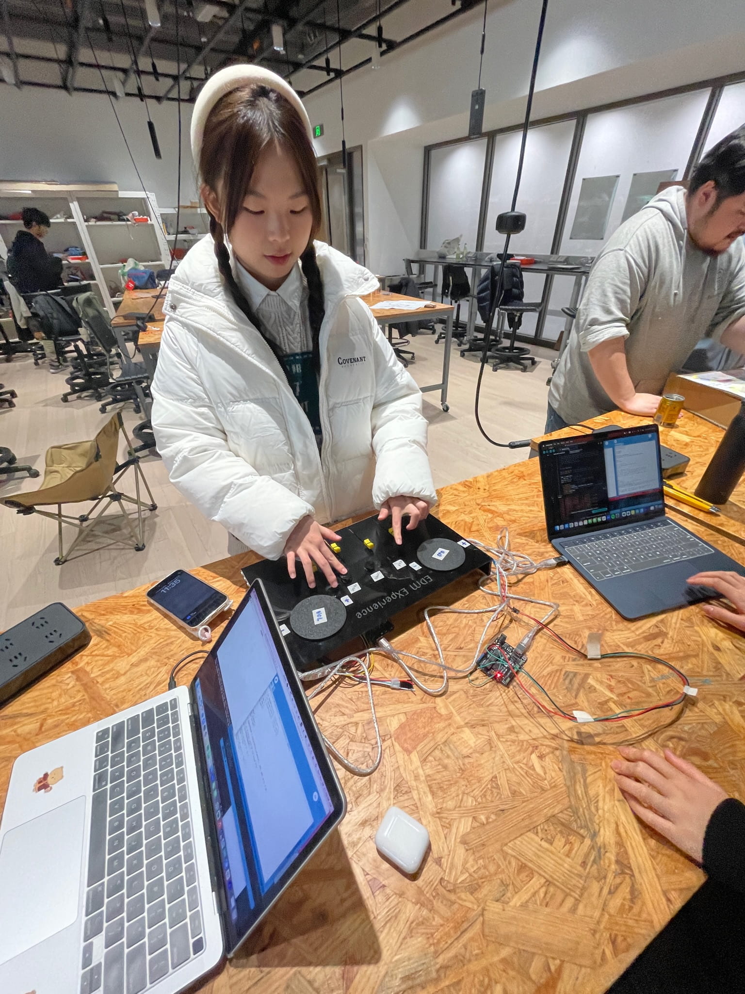
[PHOTO: user trying our prototype during user testing session]
[VIDEO: our friends messing with the functions]
[VIDEO: TA playing with our project]
FABRICATION AND PRODUCTION
Material Selection and Initial Steps
After consulting with Professor Andy, we changed a few components of the initial idea. We took away the focus on the lights, focusing in on the soundboard component as well as the sound effects we would try to use. We then identified the necessary materials: one neopixel strip, two rotary encoder turntables, three buttons, and four slide potentiometer amps. Collecting these materials involved reaching out to classmates for extra slider potentiometers and obtaining rotary encoders from the equipment room. The initial focus was divided between my partner and me, with me handling the physical components and my partner initiating the code.
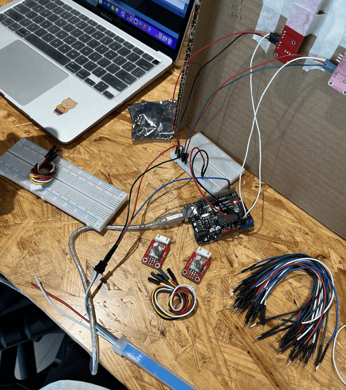
[PHOTO: our materials for the prototype]
Design and Fabrication
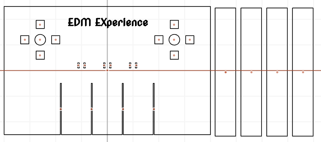
Utilizing cuttle.xyz, I designed the soundboard base and laser-cut black acrylic to achieve the desired sleek, clean, dark appearance reminiscent of a classic soundboard. Assistance from a TA was sought to create the 3D design for the turntables attached to the rotary encoders. Assembling the components and wiring posed challenges, particularly with short-legged button wiring that required meticulous handling to ensure proper triggering.
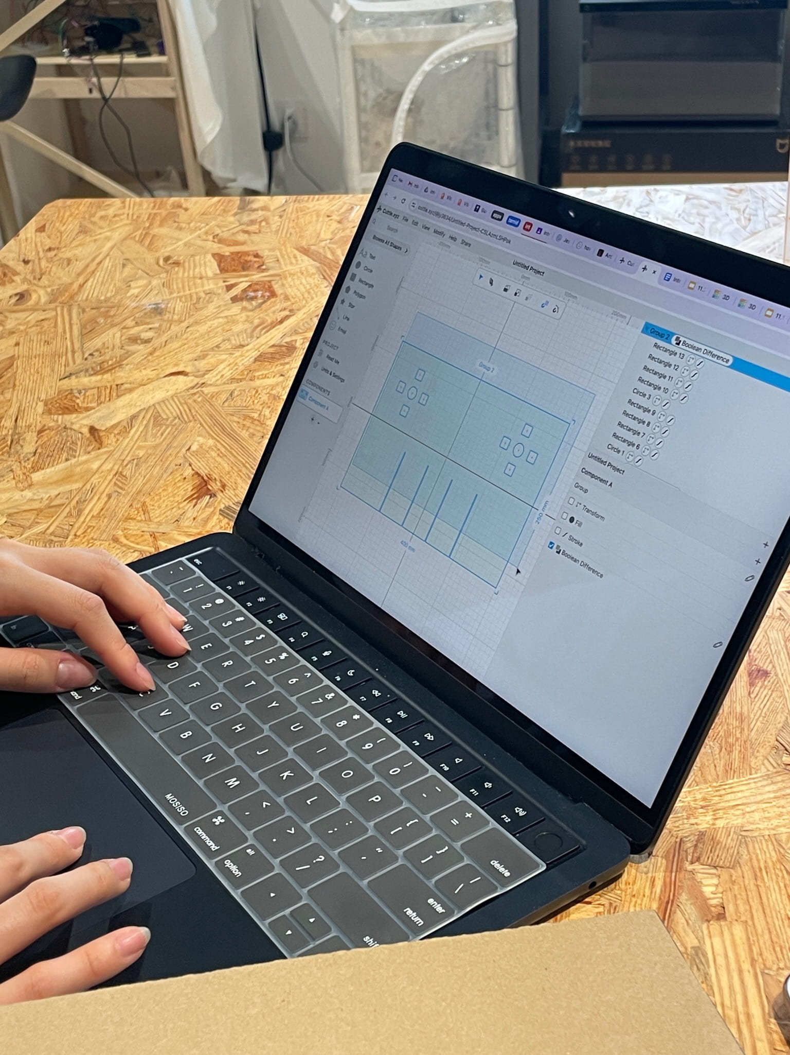
[PHOTO: working on cuttle.xyz for the laser cutter design]
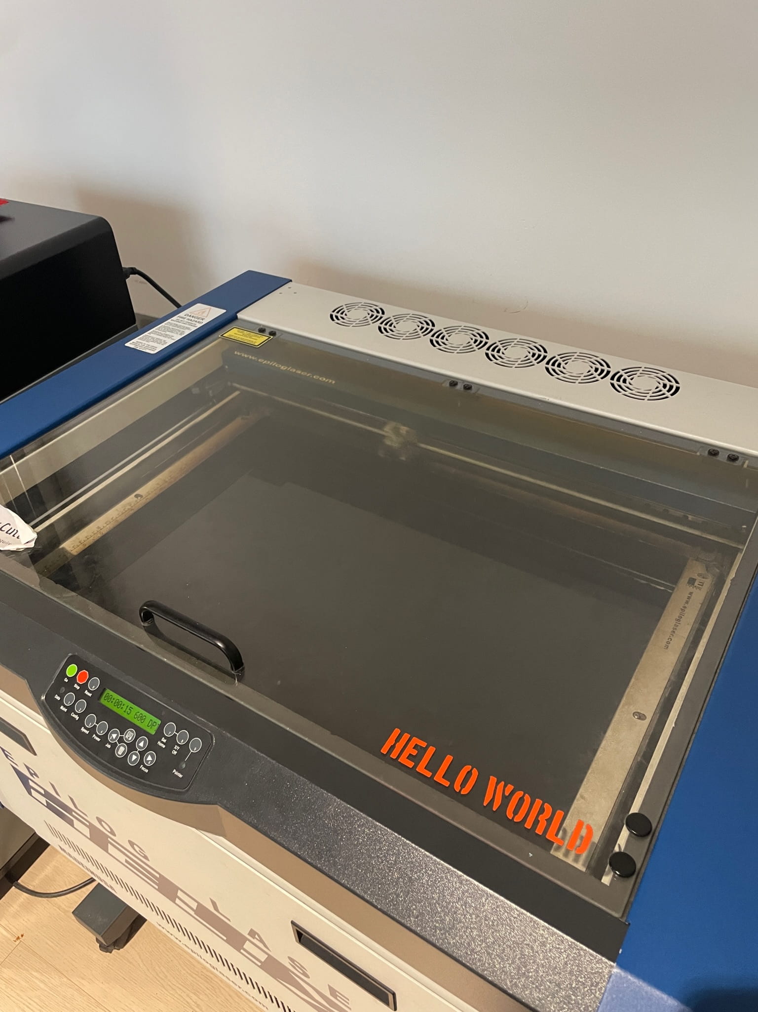
[PHOTO: laser cutting process]
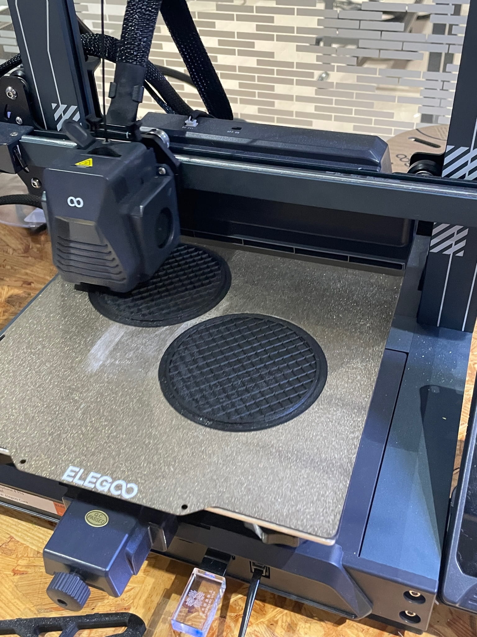
[PHOTO: 3D printing the turntables]
Coding Challenges
We quickly realized that the bulk of our project revolved around coding. My partner concentrated on the code for the rotary encoder turntables and buttons, while I focused on finding suitable sound files, stems, and coding for the slider potentiometers. Combining codes proved to be a significant challenge during fabrication. For instance, when merging code for LEDs with code for the speed/frequency rotary encoder, issues arose, rendering both non-functional. This experience taught us a valuable lesson – work on one component at a time, ensure individual functionality, and then integrate them when confident in the code.
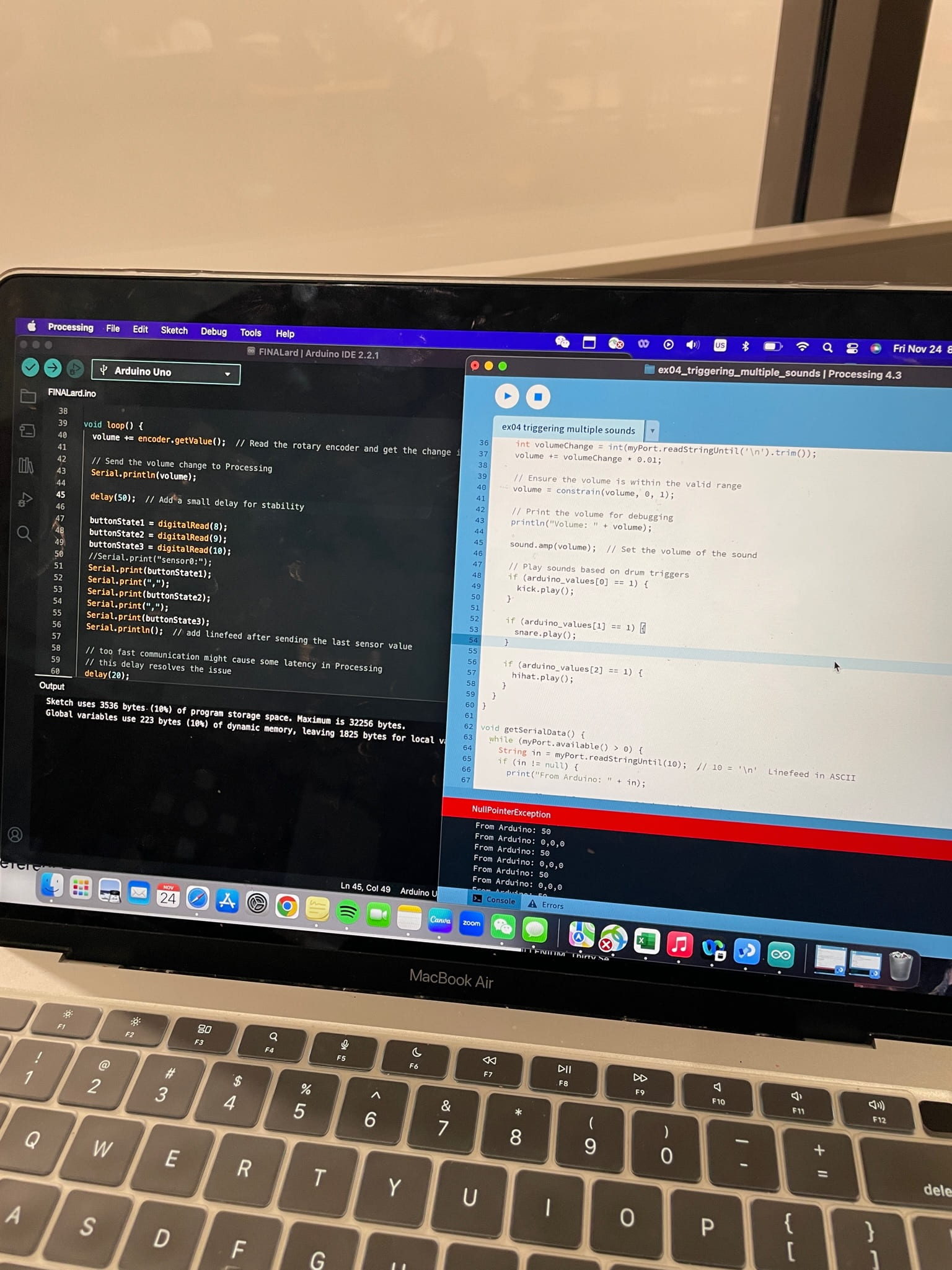
[PHOTO: the code at the beginning of the process]
Consideration of Alternatives
Throughout the production process, we continually evaluated alternatives. For instance, we considered various materials for the soundboard base but were introduced to the black acrylic by Dalin and immediately settled with that for its aesthetic appeal. The design of our project allowed us to reject options that didn’t align with our goals and refine our choices based on practical considerations. For the sound functions, we considered using effects such as low pass filter, high pass filter, and reverberation but realized that the sound effects would not be ideal for a realistic DJ soundboard. We considered the sound effects but wanted our soundabord to as closely resemble the real professional versions so we settled to use the sliders for volume adjustment on multiple stems.
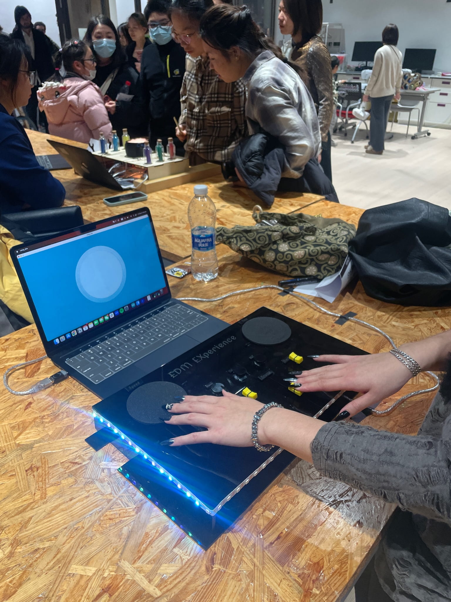
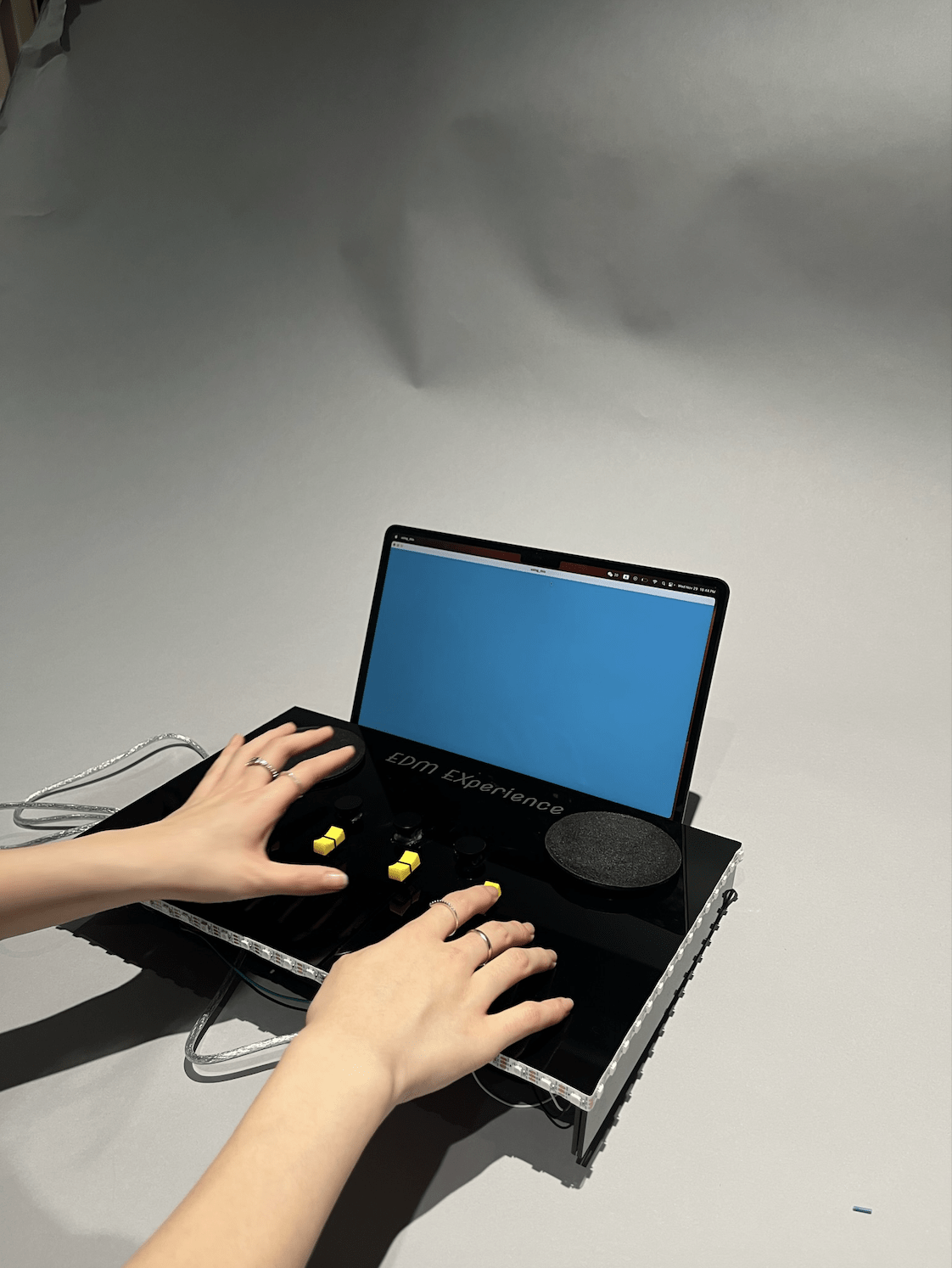
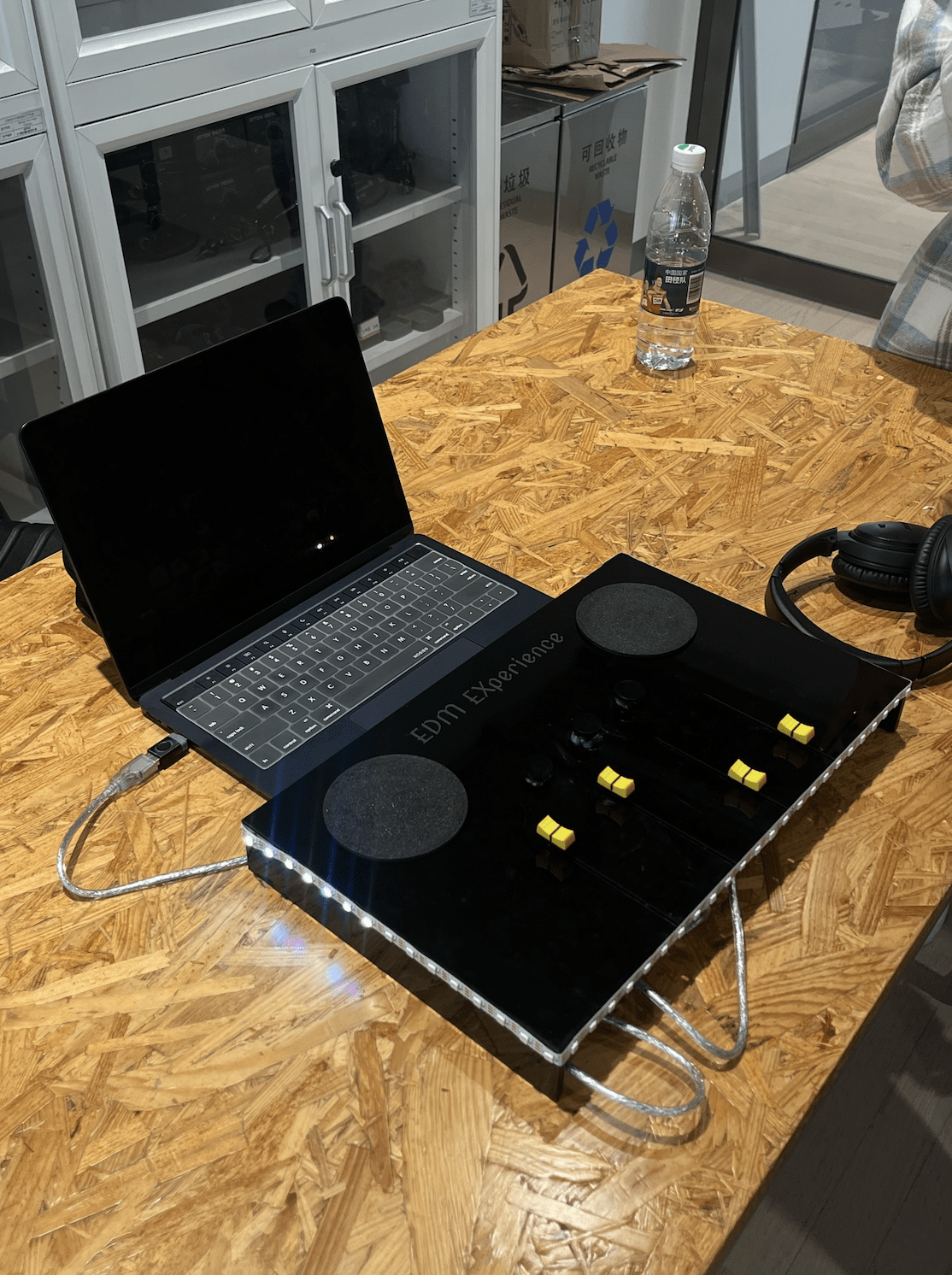
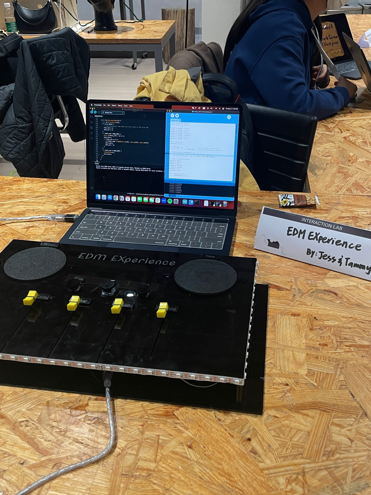
[PHOTOS: our completed project]
[VIDEO: presentation day user]
[VIDEO: myself testing on presentation day]
CONCLUSIONS
The primary goal of our project was to provide an immersive and enjoyable experience, enabling users to have fun exploring the world of EDM while momentarily detaching from the challenges of school life. The project prioritized user engagement and creative expression, offering tools for manipulating various sound features and components, fostering a sense of creative freedom.
In assessing whether our project achieved its goals, I am pleased to say that, based on audience responses, it successfully fulfilled its intended purpose. Users, ranging from children to classmates and adults, expressed enjoyment in playing with the sound production process through our user-friendly interface. Notably, during the IMA show, users engaged deeply, often lingering to fully grasp the feeling of using our soundboard before leaving satisfied. Even those with limited knowledge of music production components tested each element separately, gradually immersing themselves in the experience and having fun with their music. Moreover, I think our project results align with my definition of interaction based on users’ reactions and watching them create a dynamic conversation between their own input and the music produced by the soundboard.
[VIDEO: IMA show baby DJ]
Considering areas for improvement, given more time, I would enhance the project by adding additional controls, sound effects, and a more extensive library of music files. This expansion would allow users to further customize their experience, choosing music that caters to their preferences and elevating the overall enjoyment of the project.
From our accomplishments, I take away a deep sense of satisfaction with the project and the overall course. I loved using my own creation, playing with the beat drops and envisioning a real stage experience. The successful execution of our goal to share the thrill of playing with EDM sounds with others reinforces the significance of hands-on, interactive projects in learning and creative expression.
[VIDEO: myself playing with our project]
DISASSEMBLY
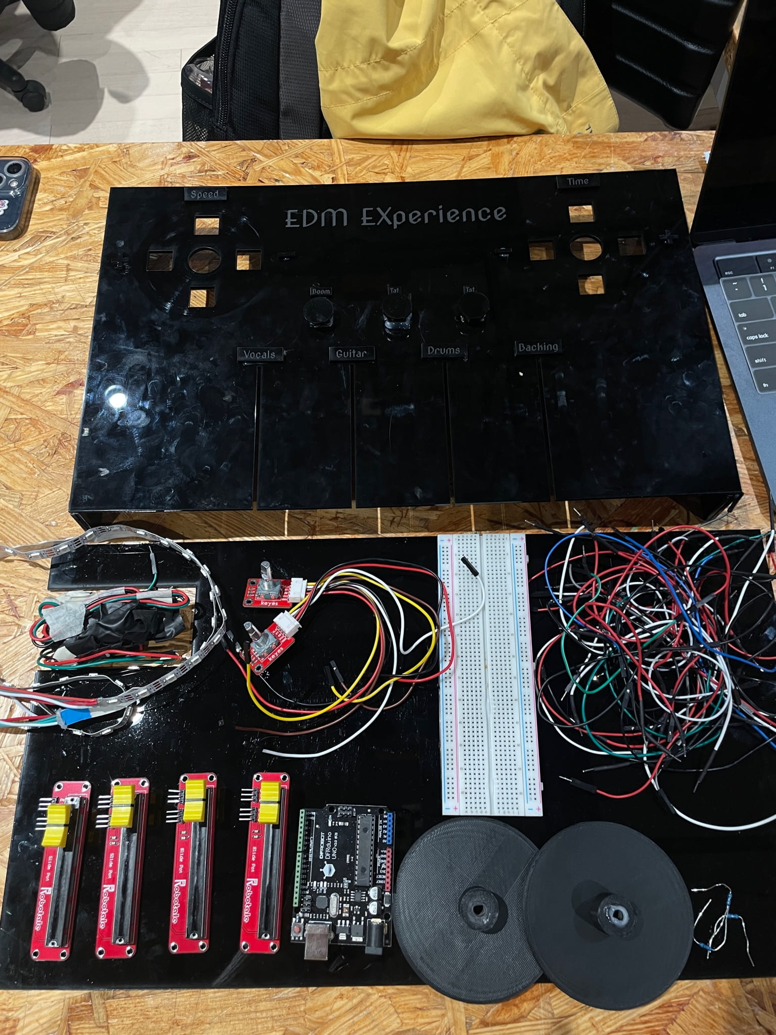
[PHOTO: our disassembled project – post IMA show]
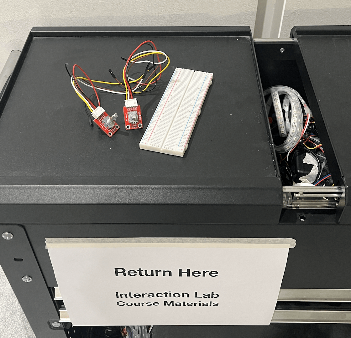
[PHOTO: returning our materials]
APPENDIX
Materials List:
- 1 Neopixel Strip
- 2 Rotary Encoders, 2 Turntables
- 3 Buttons
- 4 Slider Potentiometers
- Black Acrylic
- Arduino Uno
- Breadboard
- Wires
Cuttle XYZ:

TinkerCad:
Full Code – Arduino:
#include <ClickEncoder.h>
#include <TimerOne.h>
#include <FastLED.h>
//neopixels
#define NUM_LEDS 60 // How many LEDs in your strip?
#define DATA_PIN 7 // Which pin is connected to the strip’s DIN?
CRGB leds[NUM_LEDS];
int next_led = 0; // 0..NUM_LEDS-1
byte next_col = 0; // 0..2
byte next_rgb[3]; // temporary storage for next color
//rotary 1
#define PIN_A 2
#define PIN_B 3
#define PIN_BTN 4
//rotary 2
#define PIN_C 11
#define PIN_D 12
#define PIN_ETN 13
int buttonPin1 = 8; // number of pushbutton 1
int buttonPin2 = 9; // number of pushbutton 2
int buttonPin3 = 10; // number of pushbutton 3
int buttonState1 = 0;
int buttonState2 = 0;
int buttonState3 = 0; // variable for reading the pushbutton status
ClickEncoder encoder(PIN_A, PIN_B, PIN_BTN); // Initialize the ClickEncoder
ClickEncoder encoder2(PIN_C, PIN_D, PIN_ETN); // Initialize the ClickEncoder 2
int speed = 1.0; // initial speed
int prevSpeed = 0.5;
int speedSend = 0;
int position = 0; // initial position
int prevPosition = 0;
float jumpAmount = 0.1; // Adjust the jump amount as needed
float positionSend = 0;
void timerIsr() {
encoder.service();
encoder2.service();
}
void setup() {
Serial.begin(115200);
pinMode(8, INPUT);
pinMode(9, INPUT);
pinMode(10, INPUT);
Timer1.initialize(1000); // Initialize the timer at 1000 microseconds
Timer1.attachInterrupt(timerIsr);
pinMode(PIN_BTN, INPUT_PULLUP); // Enable pull-up resistor for the button pin
pinMode(PIN_ETN, INPUT_PULLUP); // Enable pull-up resistor for the button pin
FastLED.addLeds<NEOPIXEL, DATA_PIN>(leds, NUM_LEDS); // leds
FastLED.setBrightness(50); // external 5V needed for full brightness
leds[0] = CRGB::Red;
FastLED.show();
delay(1000);
leds[0] = CRGB::Black;
FastLED.show();
}
void loop() {
// position
position += encoder.getValue(); // Read the rotary encoder and get the change in position
float jump = position * jumpAmount;
if (position < prevPosition) {
positionSend = prevPosition – 0.1;
} else {
positionSend = prevPosition + 0.1;
}
prevPosition = position;
//speed
speed += encoder2.getValue(); // Read the rotary encoder and get change in speed
if (speed != prevSpeed) {
if (speed < prevSpeed) {
speedSend = prevSpeed – 0.1;
} else {
speedSend = prevSpeed + 0.1;
}
} else {
speedSend = prevSpeed;
}
prevSpeed = speed;
int potValue0 = analogRead(A0);
int potValue1 = analogRead(A1);
int potValue2 = analogRead(A2);
int potValue3 = analogRead(A3);
buttonState1 = digitalRead(8);
buttonState2 = digitalRead(9);
buttonState3 = digitalRead(10);
//printing position and speed
Serial.print(potValue0);
Serial.print(“,”);
Serial.print(potValue1);
Serial.print(“,”);
Serial.print(potValue2);
Serial.print(“,”);
Serial.print(potValue3);
Serial.print(“,”);
Serial.print(buttonState1);
Serial.print(“,”);
Serial.print(buttonState2);
Serial.print(“,”);
Serial.print(buttonState3);
Serial.print(“,”);
Serial.print(position);
Serial.print(“,”);
Serial.print(speed);
Serial.println();
delay(10);
while (Serial.available()) {
char in = Serial.read();
if (in & 0x80) {
// synchronization: now comes the first color of the first LED
next_led = 0;
next_col = 0;
}
if (next_led < NUM_LEDS) {
next_rgb[next_col] = in << 1;
next_col++;
if (next_col == 3) {
leds[next_led] = CRGB(next_rgb[0], next_rgb[1], next_rgb[2]);
next_led++;
next_col = 0;
}
}
if (next_led == NUM_LEDS) {
FastLED.show();
next_led++;
}
}
}
Full Code – Processing:
import processing.sound.*;
import processing.serial.*;

SoundFile sound0; //Vocals
SoundFile sound1; //Guitar
SoundFile sound2; //Drums
SoundFile sound3; //Backing
SoundFile sound4; //newboom
SoundFile sound5; //snare
SoundFile sound6; //hihat

Serial serialPort;
Amplitude analysis;

int NUM_LEDS = 60;                   // How many LEDs in your strip?
color[] leds = new color[NUM_LEDS];  // array of one color for each pixel

int NUM_OF_VALUES_FROM_ARDUINO = 9;
int arduino_values[] = new int[NUM_OF_VALUES_FROM_ARDUINO];
int prev_arduino_values[] = new int[NUM_OF_VALUES_FROM_ARDUINO];

// declare SoundFile objects
SoundFile Vocals;
SoundFile Guitar;
SoundFile Drums;
SoundFile Backing;
SoundFile newboom;
SoundFile snare;
SoundFile hihat;

float mappedPosition;
float prevmappedPosition;

void setup() {
  size(1450, 800);
  background(255);

  printArray(Serial.list());
  serialPort = new Serial(this, "/dev/cu.usbmodem1101", 115200);

  sound0 = new SoundFile(this, "Vocals.mp3");
  sound1 = new SoundFile(this, "Guitar.mp3");
  sound2 = new SoundFile(this, "Drums.mp3");
  sound3 = new SoundFile(this, "Backing.mp3");

  sound0.play();
  sound1.play();
  sound2.play();
  sound3.play();

  sound0.rate(0);
  sound1.rate(0);
  sound2.rate(0);
  sound3.rate(0);

  sound4 = new SoundFile(this, "newboom.mp3");
  sound5 = new SoundFile(this, "snare.aif");
  sound6 = new SoundFile(this, "hihat.aif");

  // create the Amplitude analysis object
  analysis = new Amplitude(this);
  analysis.input(sound0);
}

void draw() {
  background(#5FB3DB);
  getSerialData();

  // speed function
  float mappedSpeed = map(arduino_values[8], -300, 300, 0.0, 2.0);
  sound0.rate(mappedSpeed);
  sound1.rate(mappedSpeed);
  sound2.rate(mappedSpeed);
  sound3.rate(mappedSpeed);

  //println(mappedSpeed);

  // amp analysis
  float volume = analysis.analyze();
  // map the volume value to a useful scale
  float diameter = map(volume, 0, 1, 0, width);
  int ledON = floor(map(volume, 0, 1, 0, 60));
  // draw a circle based on the soundfile's amplitude (volume)
  fill(#C6E5F5);
  circle(width/2, height/2, diameter);

  // leds for the amp analysis ^^
  for (int i=0; i < NUM_LEDS-2; i=i+3) {   // loop through each pixel in the strip
    if (i < ledON) {     // based on where we are in the song
      leds[i] = color(44, 20, 142);
      leds[i+1] = color(101, 255, 13);// turn a pixel to green color
      leds[i+2] = color(13, 233, 255);// turn a pixel to color
    } else {
      leds[i] = color(0, 0, 0);
      leds[i+1] = color(0, 0, 0);
      leds[i+2] = color(0, 0, 0);  // or to black
    }
  }


  // position function
  int delta = prev_arduino_values[7] - arduino_values[7];
  if (delta != 0) {
    delta = constrain(delta, -10, 10);
    float soundOffset = map(delta, -10, 10, -0.2, +0.2);
    //println(delta + " -> " + soundOffset);

    sound0.jump(sound0.position()+soundOffset);
    sound1.jump(sound1.position()+soundOffset);
    sound2.jump(sound2.position()+soundOffset);
    sound3.jump(sound3.position()+soundOffset);
  }

  for (int i=0; i < NUM_OF_VALUES_FROM_ARDUINO; i=i+1) {
    prev_arduino_values[i] = arduino_values[i];
  }

  int amplitude0 = arduino_values[0];
  int amplitude1 = arduino_values[1];
  int amplitude2 = arduino_values[2];
  int amplitude3 = arduino_values[3];

  float volume0 = map(amplitude0, 0, 1023, 0.01, 1.0);
  float volume1 = map(amplitude1, 0, 1023, 0.01, 1.0);
  float volume2 = map(amplitude2, 0, 1023, 0.01, 1.0);
  float volume3 = map(amplitude3, 0, 1023, 0.01, 1.0);

  sound0.amp(volume0);
  sound1.amp(volume1);
  sound2.amp(volume2);
  sound3.amp(volume3);

  println("volume0", volume1);
  println("volume1", volume1);
  println("volume2", volume2);
  println("volume3", volume3);

  // play sounds based on drum triggers
  if (arduino_values[4] == 1 && sound4.isPlaying() == false) {
    sound4.play();
  }

  if (arduino_values[5] == 1 && sound5.isPlaying() == false) {
    sound5.play();
  }

  if (arduino_values[6] == 1  && sound6.isPlaying() == false) {
    sound6.play();
  }

  sendColors();
}


void getSerialData() {
  while (serialPort.available() > 0) {
    String in = serialPort.readStringUntil( 10 );  // 10 = '\n'  Linefeed in ASCII
    if (in != null) {
      //print("From Arduino: " + in);
      String[] serialInArray = split(trim(in), ",");
      if (serialInArray.length == NUM_OF_VALUES_FROM_ARDUINO) {
        for (int i=0; i<serialInArray.length; i++) {
          arduino_values[i] = int(serialInArray[i]);
        }
      }
    }
  }
}

void sendColors() {
  byte[] out = new byte[NUM_LEDS*3];
  for (int i=0; i < NUM_LEDS; i++) {
    out[i*3]   = (byte)(floor(red(leds[i])) >> 1);
    if (i == 0) {
      out[0] |= 1 << 7;
    }
    out[i*3+1] = (byte)(floor(green(leds[i])) >> 1);
    out[i*3+2] = (byte)(floor(blue(leds[i])) >> 1);
  }
  serialPort.write(out);
}