Initially, I was having a hard time coming up with an idea for my final project. I wanted to create a fun and interactive game, which is why some of the ideas I initially proposed were renditions of existing games but with a twist to make them more interactive. For example, a hot potato game that limits the time you have to pass an item around, or a maze where two players have to race through an obstacle course without triggering sensors along the way. However, after consulting with LA’s and my Professor, these ideas didn’t seem feasible in the limited time I had to create it. Hence, I continued to brainstorm specifically on the idea of making a maze game more interactive, which is how I ended up thinking of my final idea that challenges two players to work together to move a circle through a maze in Processing. I wanted users to really have to engage with each other during the interaction and that translated to physically relying on each other. This is how I came up with using light sensors attached to wristbands, so that users had to cover each other’s light sensor to get the circle to move. Additionally, I wanted the game to be more physically challenging so that users would really have to physically rely on each other, which is why I decided to make foot pedals because then the two users would have to not only hold each other to cover the light sensors, but also help each other maintain balance when pressing down on the pedals.
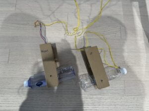
During the user testing session, it was interesting to see how different people interacted with the project. I realized that some participants wouldn’t be comfortable with physical touch, which is why I gave them the option to cover their own light sensor. My concern beforehand was that this would reduce the sense of collaboration, but interestingly it did not have that large of an impact because the players still had to work together to coordinate the movement of the circle. Another issue faced during the session was that the flex sensor in the pedals kept detaching from the cardboard, and this is because the tape I used wasn’t strong enough to hold it in place. Therefore, in order to fix this issue, I used hot glue to stick the sensor into place and that significantly improved the function and aesthetic of the pedals.
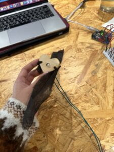
The first thing I came up with for my project was the sensors I was going to use. I believed using the light and flex sensors was the best decision for my project because I used their functions to help me ideate ways I could incorporate them in my project, which is how I ended up creating heart shaped wristbands and pedals.
The next part was drawing the maze and circle in Processing, and creating the arduino code to move the circle only when the light sensor equals to 0, which means its covered, as well as exceeds a specific range on the flex sensor that indicates its bending. The most challenging part was writing the code. LA’s helped to teach me how to use && statements so that I could account for both sensors to dictate the movement of the circle. An issue I was facing at some point was that Processing was not receiving the signals of change in the second set of the light and flex sensor, but an LA pointed out that this was because I had used the code Serial.println(); after each input from the sensors, when it should have only been placed at the end of receiving all the input from the sensors because I was confusing what information got sent from the arduino to Processing.
Serial.print(sensor0);
Serial.print(“,”); // put comma between sensor values
Serial.print(sensor1);
Serial.print(“,”);
Serial.print(sensor2);
Serial.print(“,”); // put comma between sensor values
Serial.print(sensor3);
Serial.println();
Another significant issue I faced was coding for the limits of the maze outline. As soon as the circle went outside of the barriers of the maze, I wanted the screen to turn red. My Professor proposed a way to use the pixels to determine the limits of the maze, but I was unfortunately not able to understand how to implement it. Another simpler suggestion was to use if statements so that if the circle went past a certain x and y position of the maze outline, then the screen would turn red. Below is an example of the code:
if
((x >144) && (y > 430 && y < 500))
{ background(255, 0, 0);
}
if
((y < 370) && (x > 80 && x < 180))
{ background(255, 0, 0);
}
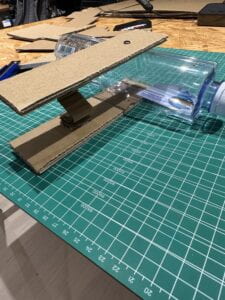
I was able to use this code for vertical lines only, which turned out to still work well. I used water bottles in the pedals because they seemed stable enough to support the weight of a foot, however because there were no springs available, I wasn’t sure how to keep the pedals in place. Therefore, I experimented with folding cardboard to create a spring, which thankfully worked.
In conclusion, the goal of this project was to render a well-known game to make it more interactive, and I believe that my project was able to achieve this goal. My expectations of my audience’s response was that they would find it as more of a challenging experience and that they would ultimately need to physically rely on each other for balance. Hence, even though this did not occur, the audience still seemed to enjoy playing it and even described it as a workout. Interestingly, after the first round when they are still getting adjusted to the way it works, they started to communicate and direct each other as to when and how to move. This demonstrates another form of working together to get through the maze. My project results align with my definition of interaction which is: Interaction is when one actor’s actions or words can influence and change the behavior of another. In relation to my project, the actions and behavior of the players not only change the position of the circle, but I also believe that their movements and decisions influence each other.
If I had more time to improve my project, I would have tried to understand my Professor’s suggestion in coding for the limits of the maze as this would enhance the function and experience of the game. Another suggestion was to make the Processing screen bigger so that users can have a better view of the maze. Something I initially wanted to do but did not have time, and was even given as a suggestion, was to add the ability to also move right as well as down. This would make the game more fun and challenging because it would really test the balance of users, especially if two flex sensors were attached to both ends of the pedal. I believe this addition would also have forced users to need to hold each other for balance, which would increase the level of collaboration. Creating this project gave me the chance to revive my ability to be creative in times of setbacks. Creating the entire pedals and springs with scraps of cardboard and plastic bottles is something I would have done when I was younger, and so this was an opportunity to use my imagination again to create things. Something of value I have learnt from my setbacks is that there is always a way to fix things. I felt hopeless when I couldn’t figure out why the code I had was not working, but with help from others, everything always was able to resolve itself. I wanted to create something fun and interactive, and I was able to do this with such a simple idea. This demonstrates that it’s more important to create an experience for users, which doesn’t necessarily call for complicated creations.
Arduino code:
Processing code:
import processing.serial.*;

Serial serialPort;

int NUM_OF_VALUES_FROM_ARDUINO = 4;  /* CHANGE THIS ACCORDING TO YOUR PROJECT */

/* This array stores values from Arduino */
int arduino_values[] = new int[NUM_OF_VALUES_FROM_ARDUINO];

float x = 12;
float y = 472;

//Boolean outMaze = false;


void setup() {
  size(500, 500);
  background(255);

  printArray(Serial.list());
  // put the name of the serial port your Arduino is connected
  // to in the line below - this should be the same as you're
  // using in the "Port" menu in the Arduino IDE
  serialPort = new Serial(this, "/dev/cu.usbmodem14301", 9600);
}

void draw() {
  background(255);
  circle(x, y, 20);
  fill(0);


  strokeWeight(10);
  line(0, 430, 80, 430);
  line(80, 430, 80, 370);
  line(80, 370, 180, 370);
  line(180, 370, 180, 300);
  line(180, 300, 288, 183);
  line(288, 183, 288, 120);
  line(288, 120, 320, 120);
  line(320, 120, 350, 44);
  line(350, 44, 472, 1);

  line(144, 500, 144, 430);
  line(144, 430, 258, 430);
  line(258, 430, 258, 310);
  line(258, 310, 346, 213);
  line(346, 213, 346, 174);
  line(346, 174, 397, 77);
  line(397, 77, 498, 46);

  //println(mouseX, mouseY);


  // receive the values from Arduino
  getSerialData();


  if ((arduino_values[1] < 60) && (arduino_values[0] == 0)) {
    // move + x value of dot
    x = x + 1;
  }

  if ((arduino_values[3] < 150) && (arduino_values[2] == 0)) {
    y = y - 1;
  }
  circle(x, y, 20);


 if((x >144) && (y > 430 && y < 500)){
  background(255, 0, 0);
  }

  if((y < 370) && (x > 80 && x < 180)){
    background(255, 0, 0);
  }

  if((x >258) && (y > 310 && y < 430)){
  background(255, 0, 0);
  }

 if((y < 430) && (x > 0 && x < 80)){
    background(255, 0, 0);
  }

  if((x > 258) && (y > 310 && y < 430)){
  background(255, 0, 0);
  }

//color c = get(floor(x), floor(y));
//println(red(c));

 //if(red(c) == 255) {
   // background(255, 0, 0);


}


// use the values like this:
//float x = map(arduino_values[0], 0, 1023, 0, width);
//float y = map(arduino_values[1], 0, 1023, 0, height);

//rectMode(CENTER);
//rect(width/2, height/2, x, y);


// the helper function below receives the values from Arduino
// in the "arduino_values" array from a connected Arduino
// running the "serial_AtoP_arduino" sketch
// (You won't need to change this code.)

void getSerialData() {
  while (serialPort.available() > 0) {
    String in = serialPort.readStringUntil( 10 );  // 10 = '\n'  Linefeed in ASCII
    if (in != null) {
     print("From Arduino: " + in);
      String[] serialInArray = split(trim(in), ",");
      if (serialInArray.length == NUM_OF_VALUES_FROM_ARDUINO) {
        for (int i=0; i<serialInArray.length; i++) {
          arduino_values[i] = int(serialInArray[i]);
        }
      }
    }
  }
}