Final Project: Make, Present, Report

Cape Your Emotion – Yijia Chen – Gottfried Haiden

  1. CONCEPTION AND DESIGN:

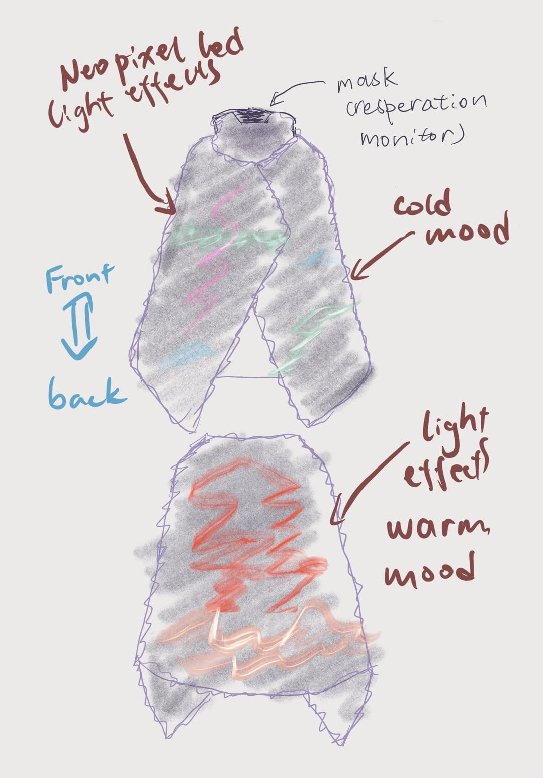
The first inspiration for this project is Jian Yu’s guest talk in an IMA workshop on wearable devices, where the artist introduces the concept of wearable accessories and clothes with LEDs. The decision of making a cape came from our shared experiences of being introverts; we conceive a wearable interactive device that can visualize the user’s emotional mood, therefore inviting more engagement between people who feel the same way. Using the pulse sensor to monitor the user’s heart rate and transform it into Neopixel LEDs light effects, our intention is to visualize emotions and break the social isolation of people, especially in this context of great pandemics.

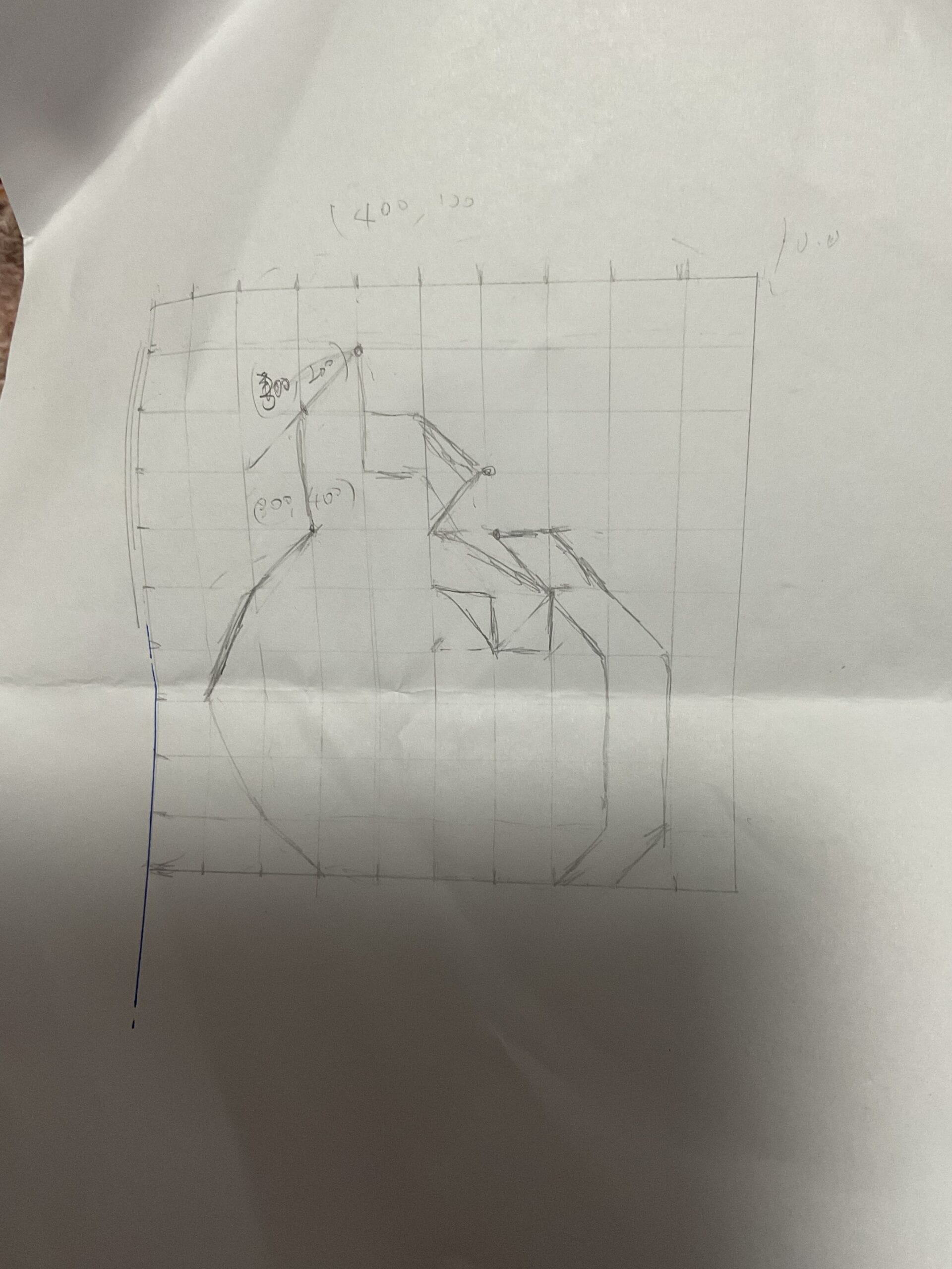
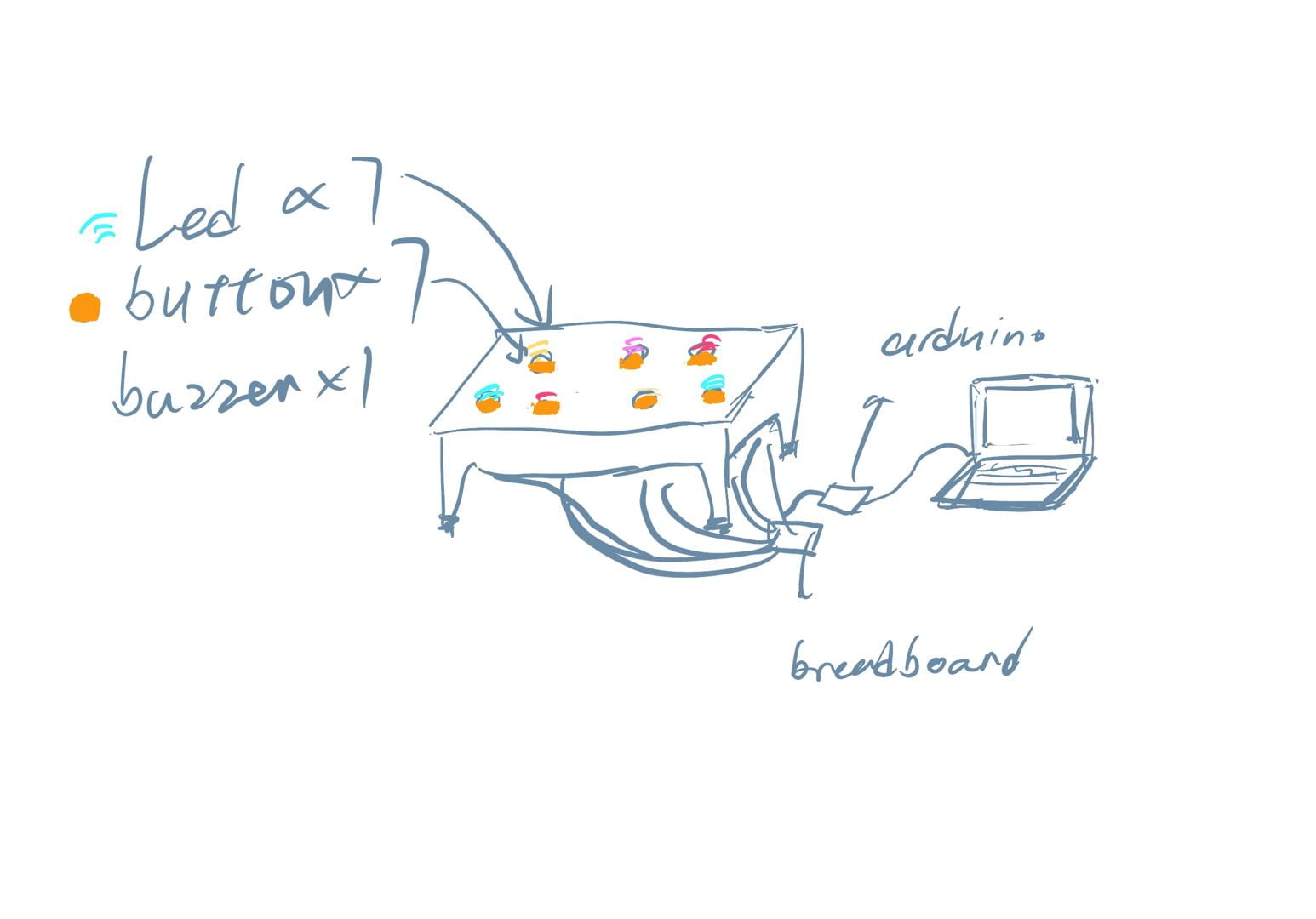
During the process of user testing, some of the users pointed out that the heart rate is reflecting more on the mental status of the user instead of the emotional mood, which inspired us to do a little research on the relation between heart rate and mental health. Therefore, on the back of the cape, we designed the side-face silhouette shape for the LED strip to suggest the spirit of the user, which also looks like a bird flying when the user moves. Although the user can not see it directly, the people around can observe the light and describe it to the user. The user test also noticed there might not be enough feedback to the user directly if the main body of the light effect is behind. In respect of that, on the left front of the cape, we add an 8*8 LED matrix that displays a beating heart so that the user can easily access their current heart rate if needed. 

We believe that through the visualizing of the heart rate, this device reflects more on the emotional stability of the user, creating an opportunity for those who feel hard to express themselves, to be noticed by people around them. This gesture appeals to people to raise awareness of mental health and care for people around them, which goes beyond human-machine interaction.

 
  1. FABRICATION AND PRODUCTION:

Since this is an untethered wearable device, the first step is to determine the fabric we want to use in making the cape. I drew a sketch for the pattern and the shape of the cape, then we both ordered two capes with different kinds of fabrics to test their light transmittance in terms of placing the Neopixel strip inside the materials and finally chose the most appropriate one. This fabric adds a hazy, diffusing effect to the LEDs. We also learned to use the sewing machine, but the shape we designed for the light strip is a little bit complicated and we had to seek some professional help in finishing it. 

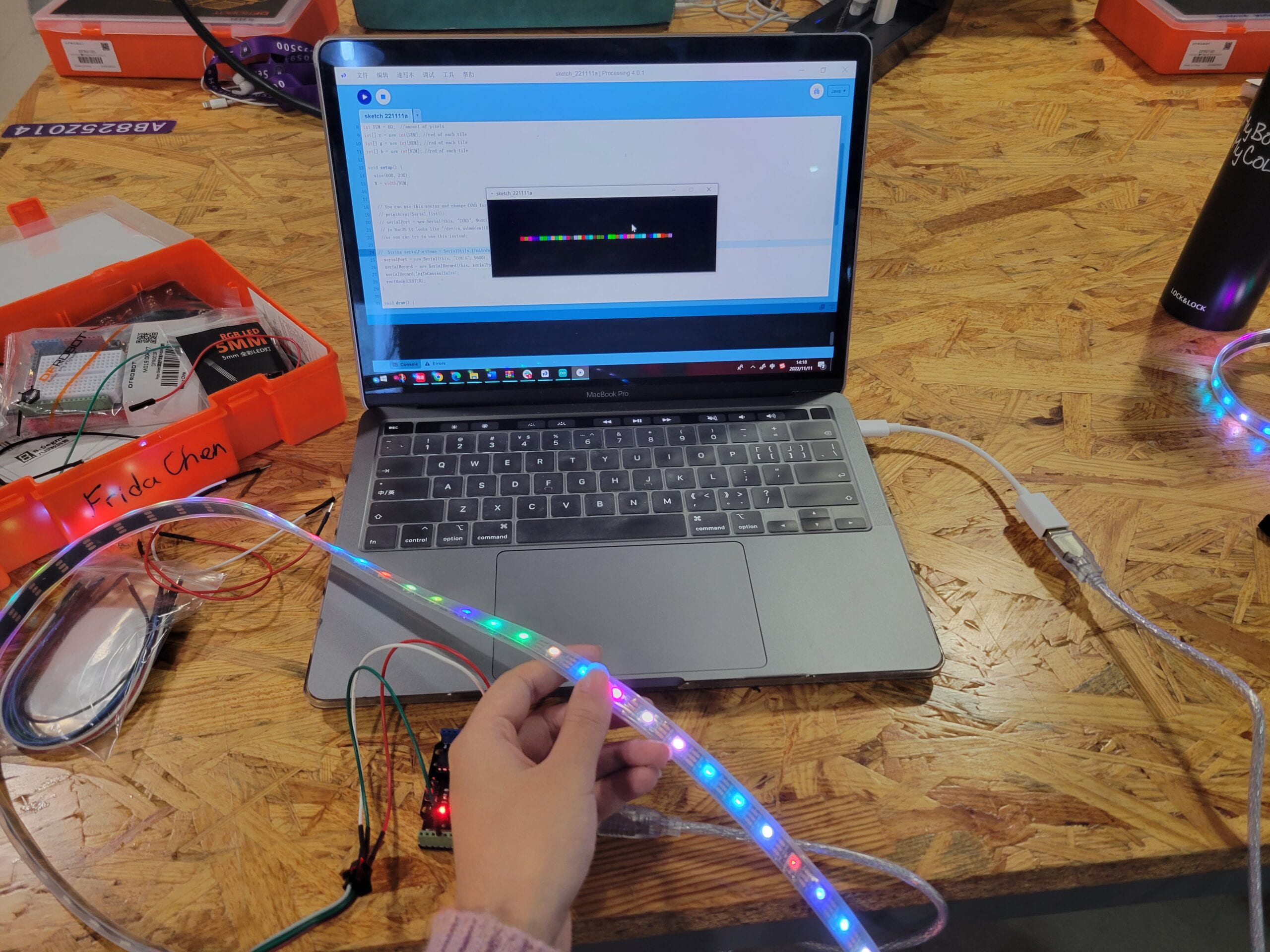
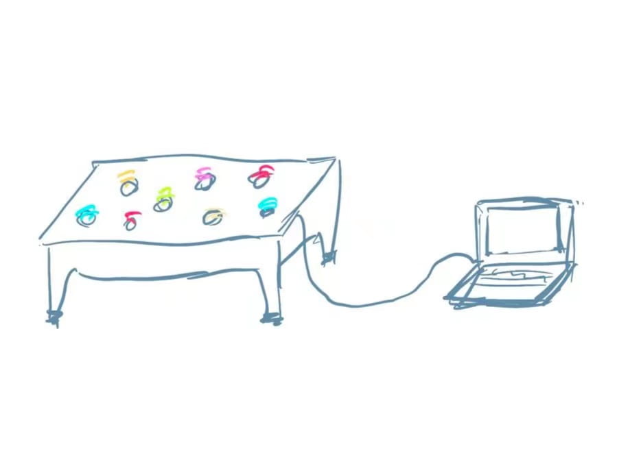
For the sensors, we started by using the finger-clipping heart rate sensor, which failed to process the data in the way we want, so we switched to the pulse sensor. It gives us feedback per second so that we could build a light effect on the heartbeat that is similar to a breathing light; it also allowed us to divide different heart rates into different levels and assign different colors for them. 


We also spent a lot of time finalizing the overall apparel design, a large part of it is the cable management which was a major issue during our user testing. The pulse sensor is supposed to be strapped tightly around the user’s right finger. So we used long wires and used sewing and glue guns to make sure the cable didn’t disconnect. We also added two pockets inside to hold the portable power. To simplify the circuit and get rid of the breadboard so that the user won’t be burdened by the weight too much, we did 3-to-1 soldering and make sure they won’t tangle up easily in different motions.

 
  1. CONCLUSIONS:

Our sole goal for this project is through visualizing the heart rate, this device can reflect on the emotional stability of the user, which creates an opportunity for those who feel hard to express themselves to be noticed and cared for by people around them. During our final presentation, our users engaged in active conversations with the audience when they trying to figure out what the visualization in the back is, which I believe is the exact the point of our design. One of our audience pointed out that this device might be useful in gym work-out, for the screen in the traditional design for portable heart monitoring sports devices are often too small and inconvenient to look at during exercising. Another audience noticed how it could be used in hospitals for people in need so that nurses and doctors can check on their patients’ statuses more easily. They all indicated the practical potential of our design. 

If there is more time, we could design the light effect more delicate and indicative, incorporating more research on this medical aspect. We also thought about adding processing extensions like some small game using the heartbeat as an input, but it seems to be a little bit jarring with the device’s nature as an untethered wearable device. In conclusion, I believe this device has achieved what I envisioned for it as an interactive installation: it invites interaction constantly and not only on a human-machine level but more deeply on a human-human level. 

(For some reason uploading new images in this new post kept failing for days, so these videos are all I got for now and I hope they can make up as visual references.  )

  1. ANNEX
#include 

#define NUM_LEDS1 60
#define NUM_LEDS2 64

#define DATA_PIN1 3
#define DATA_PIN2 6

CRGB leds1[NUM_LEDS1];
CRGB leds2[NUM_LEDS2];

int fade = 0;

int heart[14] = { 11, 12, 13, 17, 21, 25, 29, 34, 38, 42, 46, 50, 51, 52 };

/*  Getting_BPM_to_Monitor prints the BPM to the Serial Monitor, using the least lines of code and PulseSensor Library.
 *  Tutorial Webpage: https://pulsesensor.com/pages/getting-advanced
 *
--------Use This Sketch To------------------------------------------
1) Displays user's live and changing BPM, Beats Per Minute, in Arduino's native Serial Monitor.
2) Print: "♥  A HeartBeat Happened !" when a beat is detected, live.
2) Learn about using a PulseSensor Library "Object".
4) Blinks LED on PIN 13 with user's Heartbeat.
--------------------------------------------------------------------*/

#define USE_ARDUINO_INTERRUPTS true  // Set-up low-level interrupts for most acurate BPM math.
#include    // Includes the PulseSensorPlayground Library.

//  Variables
const int PulseWire = 0;  // PulseSensor PURPLE WIRE connected to ANALOG PIN 0
const int LED13 = 13;     // The on-board Arduino LED, close to PIN 13.
int Threshold = 550;      // Determine which Signal to "count as a beat" and which to ignore.
                          // Use the "Gettting Started Project" to fine-tune Threshold Value beyond default setting.
                          // Otherwise leave the default "550" value.

PulseSensorPlayground pulseSensor;  // Creates an instance of the PulseSensorPlayground object called "pulseSensor"
int desiredBrightness = 64;

void setup() {

  Serial.begin(9600);  // For Serial Monitor

  FastLED.setBrightness(50);


  FastLED.addLeds<NEOPIXEL, DATA_PIN1>(leds1, NUM_LEDS1);  // GRB ordering is assumed
  FastLED.addLeds<NEOPIXEL, DATA_PIN2>(leds2, NUM_LEDS2);
  // Configure the PulseSensor object, by assigning our variables to it.
  pulseSensor.analogInput(PulseWire);
  pulseSensor.blinkOnPulse(LED13);  //auto-magically blink Arduino's LED with heartbeat.
  pulseSensor.setThreshold(Threshold);

  // Double-check the "pulseSensor" object was created and "began" seeing a signal.
  if (pulseSensor.begin()) {
    Serial.println("We created a pulseSensor Object !");  //This prints one time at Arduino power-up,  or on Arduino reset.
  }
}

void loop() {

  for (int j; j < NUM_LEDS2; j++) {
    leds2[j] = CRGB::Black;
  }
  for (int j; j < 14; j++) { leds2[heart[j]] = CRGB::Red; } FastLED.show(); delay(50); int myBPM = pulseSensor.getBeatsPerMinute(); // Calls function on our pulseSensor object that returns BPM as an "int". // "myBPM" hold this BPM value now. if (pulseSensor.sawStartOfBeat()) { desiredBrightness = 64; // Constantly test to see if "a beat happened". Serial.println("♥ A HeartBeat Happened ! "); // If test is "true", print a message "a heartbeat happened". Serial.print("BPM: "); // Print phrase "BPM: " Serial.println(myBPM); // Print the value inside of myBPM. } if (desiredBrightness > 0) {
    desiredBrightness = desiredBrightness - 4;
  }
  FastLED.setBrightness(desiredBrightness);
  FastLED.show();
  delay(10);


  if (myBPM >= 55 && myBPM < 70) {
    for (int i = 0; i < NUM_LEDS1; i++) { // and set the amount of "red" to be proportional // to the heartbeat value leds1[i] = CRGB::DeepSkyBlue; } // update the NeoPixel chain FastLED.show(); // and sleep a bit delay(10); } else if (myBPM >= 70 && myBPM < 90) {
    for (int i = 0; i < NUM_LEDS1; i++) { // and set the amount of "red" to be proportional // to the heartbeat value // leds[i] = blend(CRGB::DeepSkyBlue, CRGB::Amethyst, fade); leds1[i] = CRGB::DarkOrchid; } // update the NeoPixel chain FastLED.show(); // and sleep a bit delay(10); } else if (myBPM >= 90 && myBPM < 110) {
    for (int i = 0; i < NUM_LEDS1; i++) { // and set the amount of "red" to be proportional // to the heartbeat value // leds[i] = blend(CRGB::Amethyst, CRGB::LemonChiffon, fade); leds1[i] = CRGB::DarkOrange; } // update the NeoPixel chain FastLED.show(); // and sleep a bit delay(10); } else if (myBPM >= 110 && myBPM < 125) {
    for (int i = 0; i < NUM_LEDS1; i++) { // and set the amount of "red" to be proportional // to the heartbeat value // leds[i] = blend(CRGB::LemonChiffon, CRGB::DeepPink, fade); leds1[i] = CRGB::FireBrick; } // update the NeoPixel chain FastLED.show(); // and sleep a bit delay(10); } else if (myBPM >= 125 && myBPM < 140) {
    for (int i = 0; i < NUM_LEDS1; i++) {
      // and set the amount of "red" to be proportional
      // to the heartbeat value
      // leds[i] = blend(CRGB::DeepPink, CRGB::FireBrick, fade);
      leds1[i] = CRGB::Red;
    }
    // update the NeoPixel chain
    FastLED.show();
    // and sleep a bit
    delay(10);
  }
}
 

Final Project: Proposal Essay

Cape Your Emotion

Starting from the shared experiences of being introverts, we conceive a wearable interactive device that can visualize the user’s emotional mood and therefore, invite more engagement between people who feel the same way. Our core concept is to visualize emotions and break the social isolation of people, especially in this context of great pandemics.

For the apparel design, we want to start with the model of a cape combined with a mask, so it’s more unisex and size friendly. The addition of a mask is an inference to the pandemic and also serves as a good connection to the heart rate sensor. Using heart rate sensors or motion sensors that can monitor the user’s emotional state/state of excitement, and further incorporating of a deformable membrane as the main material for the cape, we aim at turning these inputs into light effects through Neopixel LEDs or other LEDs and offer different moods to visualize the emotions of the user.

We believe that the two essential factors for this project are the continuity of interaction and aesthetic visualization. First, by saying continuity, we want the audience to have immediate and dynamic feedback throughout the period when they wear the cape. That means the NeoPixels on the cape will simultaneously change their color and pattern along with the change of the user’s heart rate or respiration frequency to show how the user feels from their physical reactions.

Second, we hope that the color and pattern derived from the user’s emotions can be visualized in abstract aesthetics so that they can be shared and appreciated by others. This process can create a resonance of emotions among people, and the abstracted light effects will allow them to communicate on not only an emotional but a spiritual level. In this era of the pandemic, where “social distance” would still function as an estrangement among people, our project offers a way out for the users to communicate beyond the barricade.

Technical Challenges:

To break down each technical component, in the main body of this device we will use either an Ear clip heart rate sensor or a vibration sensor to monitor the user’s heart and respiratory frequency. This is to roughly categorize the user’s mood into active/calm, and from here, we can make more detailed and different visualizations of their emotions. 

After realizing this main body, we are also considering adding more visualization by changing the cape’s material into a deformable membrane, so that it invites people who are not wearing the device to interact with the wearer. In order to pick up deformation, we will use either flex/stretch sensors or using an invisible infrared (IR) LED to measure the brightness reflected off the fabric with an IR photoresistor while illuminating the back side of the fabric.

Of course, we will prepare enough LEDs and sensors. We will also test a lot of fabrics to see what goes well with these technical components. Since the detection of heart rate and the making of membranes are all brand new to us, we anticipate a lot of technical challenges lying ahead. 

Context of Significance:

In Edmonds’ essay, he proposes two definitions of interaction, the first of which is  “Dynamic-Interactive” in that the ‘viewer’ receives different feedback after one’s action becomes an input into the installation. A more complicated interaction would be the Dynamic-Interactive (Varying), during which the feedback from Dynamic-Interactive can be learned and has an impact on later engagement with the user and create a cycle of responses. In this inal project, I will try to add more in this “stage 3” to really engage with the user in a more stimulating manner.

This is one of the major inspirations for our project. The way this wearable installation integrates the fabric pattern with a light effect provides a very good example for us to design our pattern.


Final Project: Three Project Proposals

  1. The Cape (collaborating with Harrison)

Starting from the shared experiences of being introverts, we conceive a wearable interactive device that can visualize the user’s emotional mood and therefore, invite more engagement between people who feel the same way. The mechanism of this device is based on sensors to monitor the user’s heartbeat and respiratory frequency, and through Arduino/processing components, these data will be converted and visualized into light effects through Neopixel LEDs and other potential components. For the apparel design, we want to start with the model of a cape combined with a mask, so it’s more unisex and size friendly, while the form of a mask could easily connect with the monitoring of respiration. The ultimate concept is to break the social isolation of people in the pandemic era.  

Draft:

2. Crystal Gazing

This concept is based on the old form of crystal gazing divination, but instead of a one-way reading of the user, this project will reveal the answers through constant interaction with the user.  Attaching a temperature sensor to the crystal ball and using the output of the sensor as a variable to an Etch-A-Sketch-like visualization using processing. Therefore, when the users put their hands on it, the temperature will go up, and the processing function will start to draw a one-line picture that looks like a revelation of their thoughts or the answer to their questions. 

3. Cyber Reincarnation. 

In most video games, the player gets to change their digital appearance and create their avatars, which is like reincarnation in cyberspace. This project will collect personal data from users like a heartbeat, body temperature, or motions to create a two-dimensional image of them that will change if the player’s motion is changed. If the player acts aggressively or violently, the image will become more fragmented and twisted; if the player is calm and gentle, the image will be in more tuned colors and softer lines. The idea was to challenge the current identity constructions based on common notions of genders or other problematic definitions and provide a new angle of viewing identities in cyberspace. 


Recitation 7: Neopixel Music Visualization

Task #1: Test the NeoPixel

Step 1Connect the NeoPixel Led strip to your Arduino as shown on the diagram, download the library and use the sketch to control the NeoPixel. This is an easy step for we have tried it in class before and I succeed as I followed the steps. 

Task #2: Use your computer to light up NeoPixels

After installing the SerialRecord library as instructed and copying the code, I tested it with the serial monitor and it worked well. Then I program my Processing sketch using the code we used in class before.

Task #3: Add Music!

Step 1: Download this sketch which plays an audio file (located in the data folder) and analyzes the amplitude. Replace beat.aiff with a song you like. This is the relatively easy part

Step 2: Modify this sketch so that it creates a visualization on the screen AND on the NeoPixel strip. For this, you want to merge code from the Processing sketch from Task into #2 into the current one. I

n merging the code, I came across with a problem, which is the feedback value from the serial monitor is larger than the sequence number of led, which results in an early end of the playing of the song. With the heartful help of the learning assistants, I successfully modified the range of the values and solved this bug.

The bug:

Step 3: Add different light effects for the song you have chosen. 

Final effect with the bug fixed (a certain led will change to a certain color in relation to the volume of the music):

Here’s the final code:

import processing.sound.*;

SoundFile sample;
Amplitude analysis;

import processing.serial.*;
import osteele.processing.SerialRecord.*;

Serial serialPort;
SerialRecord serialRecord;

int W;         //width of the tiles
int NUM = 60;  //amount of pixels
int[] r = new int[NUM]; //red of each tile
int[] g = new int[NUM]; //red of each tile
int[] b = new int[NUM]; //red of each tile
float x;
float a;

void setup() {
  size(640, 480);
 
  // load and play a sound file in a loop
  sample = new SoundFile(this, "1.mp3");
  sample.loop();

  // create the Amplitude analysis object
  analysis = new Amplitude(this);
  // analyze the playing sound file
  analysis.input(sample);
  
  serialPort = new Serial(this, "COM16", 9600);
  serialRecord = new SerialRecord(this, serialPort, 4);
  serialRecord.logToCanvas(false);
  rectMode(CENTER);
}

void draw() {
  println(analysis.analyze());
  background(111, 255, 242);
  noStroke();
  fill(255, 0, 150);

  float volume = analysis.analyze();
  float diameter = map(volume, 0, 1, 0, width);
  circle(width/2, height/2, diameter);
  
  
  x = volume * 100;
  a = map(x, 0, 100, 0, 60);
  int n = floor(constrain(a, 0, 255));

    r[n] = floor(random(255));
    g[n] = floor(random(255));
    b[n] = floor(random(255));

    serialRecord.values[0] = n;     // which pixel we change (0-59)
    serialRecord.values[1] = r[n];  // how much red (0-255)
    serialRecord.values[2] = g[n];  // how much green (0-255)
    serialRecord.values[3] = b[n];  // how much blue (0-255)
    serialRecord.send();            // send it!
} 


Final Project: Research

Definition:

Edmonds defines a qualifying interactive process as the “Dynamic-Interactive”: which ensures the ‘viewer’ has “an active role in influencing the changes in the art object”, as the work gives different feedback to what the person does. And then there’s a more complicated version of that named Dynamic-Interactive (Varying). In this situation, the feedback from the second stage of Dynamic-Interactive has “a modifying agent that changes the original specification of
the art object”, which allows it to learn from the precious engagement with the user and create a cycle of responses. 

Edmonds’ depiction of an interactive installation can collect a history of experiences that fits in with my previous understanding of an interactive installation. The midterm project I made succeed in letting the user explore the instrument on their own, but did not produce enough secondary feed back to keep them engaged. In my final project, I will try to add more in this “stage 3” to really engage with the user in a more stimulating manner.

Researched Project 1

Firewall–Aaron Sherwood & Michael Allison

Firewall is an interactive media installation, the main body of which is a stretched sheet of spandex “acts as a membrane interface sensitive to depth that people can push into and create fire-like visuals and expressively play music”.

The artists revealed their inspiration as from “death and experience of reality”, as the membrane “represents a plane that you can experience but never get through” between the rigid boundary of life and death. The piece was made using Processing, Max/MSP, Arduino and a Kinect. When someone presses into it the visuals react around where the person presses, and the music is triggered. An algorithm created with Max allows the music to speed up and slow down and get louder and softer, based on the depth. This provides a very expressive musical playing experience, even for people who have never played music before.

What I take away from this work is how it produces intricate instant feedback, and how the constantly changing responses from light and sound can intrigue a player for a long time, and even allow them to figure out an effective way of playing this installation like a real instrument. If I want to incorporate sound with light effects in my project, this is a very good model to learn from. 

Researched Project 2

Rafael Lozano-Hemmer: Bilateral Time Slicer, 2016

The main body of this mirror-like installation based on a “biometric tracking system finds the axis of symmetry of members of the public using face detection”, which allows the computer to splits the live camera image of the users into two slices mixed with previous users’ images.  When no user is occupying the camera, these previously recorded slices “close and rejoin creating a procession of past recordings”. This installation is inspired by time-lapse sculptures and masks in ancient traditions.

I believe this successfully re-enacts the idea of maskin in the current age of digital identity, and the memory function allows it to reflect on its interaction with different users to produce profiling of identities in modernity. If I want to continue my idea on a project that can regenerate a personal image for the users that challenges their current belief of identities, I will think about how to collect samples and data from the users and mixed them in an effective way to produce an image that can produce constant feedback to intrigue the user. 

Recitation 6: Animated Post

Step 1

To draw the eye, I learned to use the BezierVertex function. After multiple attempts to find the right value for the handle, I finally succeed in creating an ellipse that was good enough for an orbit. 

Step 2

Using the parameters of x & y and the nested for loop, I successfully fill the canvas with my eyes.

Step 3

For some reason, my computer’s screen recording function isn’t working, so I only took a video of how it worked. I use the mousePressed function to change the color and create a flashing effect. 

Here’s the full code:

void setup() {
  size(1024, 768);
  background(185, 90, 64);
}

void draw() {

  for(float i = 0; i < 100; i++) { 
    for(float m = 0; m < 100; m = m + 2 ) {
      //eye(i*110+60, 50);
      eye(i*110+60, m*50);
  }
  }
    
}

void eye(float eyeX, float eyeY) {
   noStroke();
  fill(151, 250, 249);
  beginShape();
  vertex(eyeX-50, eyeY);
  bezierVertex(eyeX-50, eyeY-50, eyeX+50, eyeY-50, eyeX+50, eyeY);
  bezierVertex(eyeX+50, eyeY+50, eyeX-50, eyeY+50, eyeX-50, eyeY);
  endShape();

  //fill(0);
  //circle(eyeX, eyeY, 50);
  if(mousePressed && (mouseButton == LEFT)){
  fill(random(0, 255), random(0, 255), random(0, 255));
  }
  circle(eyeX, eyeY, 50);
  fill(255);
  circle(eyeX+10, eyeY-10, 20);
}


And here’s the video:


Recitation 5: Processing Basics

Step 1: Choose your motif
This is the photo of a cat that I took a year ago. I will try to recreate it in an abstract way.

Step 2: Draw your image on paper

Step 3: Draw your image with code

I added a little bit of glitching effect apart from the abstract shape.

void setup() {
  //size(1000, 1000);
  fullScreen();
}
void draw() {
  // Your drawing code goes here
  background(0);
  stroke(random(255), random(255), random(255));

  
  smooth();
beginShape();
fill(255, 200, 111);
vertex(400, 100);
vertex(300,200);
vertex(400, 200);
vertex(400, 100);

//endShape();
  
  strokeWeight(10);
  line(400, 100, 300, 200);
  line(300, 200, 300, 400);
  line(300, 400, 200, 500);
  line(200, 500, 100, 700);
  line(100, 700, 300, 1000);
  line(300, 1000, 800, 1000);
  line(800, 1000, 900, 900);
  line(900, 900, 900, 600);
  line(900, 600, 700, 400);
  line(700, 400, 600, 400);
  line(600, 400, 700, 500);
  line(700, 500, 500, 400);
  line(500, 400, 600, 300);
  line(600, 300, 500, 200);
  line(500, 200, 400, 200);
  line(400, 200, 400, 100);
  endShape();
  
  
} 

Midterm Project: Make, Present & Report

A. Back-to-the-Future Music Box- Yijia Chen – Gottfried

B. CONTEXT AND SIGNIFICANCE
At the previous stage of my research, I define the concept of interaction as “an installation that gives the user instant feedback once the interaction is initialed, which affects the next move of the user”. Based on this concept, I proposed an interactive keyboard with light effects. In the actual making process, we decided to remove the light effect functions and added a jukebox-like function instead. I mostly contribute to the making of basic components in the prototype, as well as the aesthetic design (the soldering of press buttons, the making and assembling of the keyboard & the music box, and all the decorations). In a sense, it is a re-creation of a retro electronic organ integrating with the concept of a retro arcade (which is not only shown in the exterior design of the box but also in the interface of the keyboard as a game handle).  We hope that it brings the simultaneous experience of playing with the arcade and exploring one’s own music. 

The original draft:

The final version:

C. CONCEPTION AND DESIGN:
The music style of our project is the 8-bit chiptune, which fits in the overall retro aesthetic. It is also easy to achieve with the buzzer we were given in the tool kit. The songs we prepared in the music box include hit songs and classic game themes in y2k, and it’s easy for the user to recreate them with the keyboard. We didn’t set any specific goals for the user to achieve, because we want the experience to have more freedom.

For the buttons, we choose the classic press buttons that have simple and vivid colors, while also giving the user a solid tactile feeling when they are pressed.  The exterior design also intends to be harmonious with each component in terms of colors and aesthetics, as I choose to imitate the exterior of an arcade game box using black paint as a base and red graffiti-style letters. I also print the album pictures of each song as well as classic arcade game thumbnails as decorations. 

D. FABRICATION AND PRODUCTION:
As I mentioned above, I mostly contribute to the overall aesthetics and concept of the prototype, as well as the making and assembling of several components. My groupmate is in charge of the coding and the realization of the circuit. It means that after the main theme and functions are decided, we can work individually and simultaneously at the beginning of the process, and collaborate at the end. 

One major problem of this working pattern is that the coding has too many variables when we first tried to put everything together, the circuit didn’t work, and it took a long time to de-bug while also finding out if some of the components had mal-functions. This led to the failure in our user testing process, during which we haven’t found the exact problem and had to spend most of the time fixing the prototype rather than demonstrating it. It did teach us the importance of using appropriate components, as we switched to the buttons we are using now, which had more stable connections; we also fixed the major bug in coding that led to the result of only one button that wouldn’t stop buzzing. 

The first version we presented in the user testing and the bug we came across:


E. CONCLUSIONS:

As I put in the beginning, the interaction is fully achieved when the user’s moves are influenced by the feedback from the keyboard. Our goal is to allow the user to explore the music world between the past and future; in this case, the jukebox function represents the past, and the free interaction with the keyboard signifies the future.

We got a lot of useful feedback after the presentation, I do think there’s a lot to be improved in terms of the interaction process. The freedom led to a lack of purposes and goals in the interaction, which may confuse the user. Professor Margaret Minsky mentioned that we could have explored more with the “reverse Shazam” effect, which let the user imitate the tunes they heard, and when they recreate the music successfully the installation will give major feedback like “you win!”. This is a very valuable suggestion for us to consider if we can do it again, for we realize that too much freedom given to the player might result in boredom and a lack of stimulation. The current design does not necessarily distinguish our prototype from any electronic organs.

Another thing that I would like to improve is our progress management as a team. Although we did communicate a lot in coordinating the respective individual working process, there were still a lot of asynchronies that lead to several last-minute refinements of the prototype. Since the division of work is very solid in my team, I have to wait for my groupmate to assemblage the circuit with them and see what could go wrong in my previous component-making process, instead of working in a dual-thread way. Our differences in personal schedules also undermine our efficiency greatly, as I could start earlier to finish my part but my teammate couldn’t. In the next group project, I will make sure we have better time management, which could be realized through a more detailed timetable of progress that takes every kind of potential accident into account, and prioritizes the coding and debugging. 

The final presentation and the player’s interaction:

F. ANNEX

The decoration materials:

Original Coding:

#define NTE1 330
#define NTE2 370
#define NTE3 410
#define NTE4 441
#define NTE5 495
#define NTE6 556 
#define NTE7 624


// constants won't change. They're used here to set pin numbers:
const int buttonPin1 = 2;     // the number of the pushbutton pin
const int buttonPin2 = 3;     // the number of the pushbutton pin
const int buttonPin3 = 4;     // the number of the pushbutton pin
const int buttonPin4 = 5;     // the number of the pushbutton pin
const int buttonPin5 = 6;     // the number of the pushbutton pin
const int buttonPin6 = 7;     // the number of the pushbutton pin
const int buttonPin7 = 8;     // the number of the pushbutton pin

int buzz = 9;

int buttonState1, buttonState2, buttonState3, buttonState4,buttonState5,buttonState6,buttonState7;
// variables will change:
int buttonState = 0;         // variable for reading the pushbutton status
// int tone[1] = {NTE1}
// int tone[2] = {NTE2}
// int tone[3] = {NTE3}
// int tone[4] = {NTE4}
// int tone[5] = {NTE5}
// int tone[6] = {NTE6}
// int tone[7] = {NTE7}

void setup() {
  Serial.begin(9600);
  // initialize the pushbutton pin as an input:
  pinMode(buttonPin1, INPUT);
  pinMode(buttonPin2, INPUT);
  pinMode(buttonPin3, INPUT);
  pinMode(buttonPin4, INPUT);
  pinMode(buttonPin5, INPUT);
  pinMode(buttonPin6, INPUT);
  pinMode(buttonPin7, INPUT);

}

void loop() {
  // read the state of the pushbutton value:
 buttonState1 = digitalRead(buttonPin1);
 buttonState2 = digitalRead(buttonPin2);
 buttonState3 = digitalRead(buttonPin3);
 buttonState4 = digitalRead(buttonPin4);
 buttonState5 = digitalRead(buttonPin5);
 buttonState6 = digitalRead(buttonPin6);
 buttonState7 = digitalRead(buttonPin7);
 

 // check if the pushbutton is pressed. If it is, the buttonState is HIGH:
  Serial.print(buttonState1);
  Serial.print(buttonState2);
  Serial.print(buttonState3);
  Serial.print(buttonState4);
  Serial.print(buttonState5);
  Serial.print(buttonState6);
  Serial.println(buttonState7);

  if (buttonState1 == HIGH) {
    // turn LED on:
    tone(buzz, NTE1);
  } else if (buttonState2 == HIGH) {
    tone(buzz, NTE2);
  } else if (buttonState3 == HIGH) {
    tone(buzz, NTE3);
  } else if (buttonState4 == HIGH) {
    tone(buzz, NTE4);
  } else if (buttonState5 == HIGH) {
    tone(buzz, NTE5);
  } else if (buttonState6 == HIGH) {
    tone(buzz, NTE6);
  } else if (buttonState7 == HIGH) {
    tone(buzz, NTE7);
  } 
  else {
    // turn LED off:
    noTone(buzz);
  }
  /*
  if (buttonState2 == HIGH) {
    // turn LED on:
    tone(buzz, NTE2);
  } else {
    // turn LED off:
    noTone(buzz);
  }if (buttonState3 == HIGH) {
    // turn LED on:
    tone(buzz, NTE3);
  } else {
    // turn LED off:
    noTone(buzz);
  }if (buttonState4 == HIGH) {
    // turn LED on:
    tone(buzz, NTE4);
  } else {
    // turn LED off:
    noTone(buzz);
  }if (buttonState5 == HIGH) {
    // turn LED on:
    tone(buzz, NTE5);
  } else {
    // turn LED off:
    noTone(buzz);
  }if (buttonState6 == HIGH) {
    // turn LED on:
    tone(buzz, NTE6);
  } else {
    // turn LED off:
    noTone(buzz);
  }if (buttonState7 == HIGH) {
    // turn LED on:
    tone(buzz, NTE7);
  } else {
    // turn LED off:
    noTone(buzz);
  }
  */

  delay(10);
}
 

The Diagram:

Recitation 4: Actuators and Mechanisms

To build this mechanism and circuit, I paired up with Maryam and we choose to use white cardboard that is harder but thinner than the most common cardboard; we did worry that it might not work because it’s thinner, but it turns out working perfectly.

Here’s the code we’re using:

/*
 Stepper Motor Control - one revolution

 This program drives a unipolar or bipolar stepper motor.
 The motor is attached to digital pins 8 - 11 of the Arduino.

 The motor should revolve one revolution in one direction, then
 one revolution in the other direction.


 Created 11 Mar. 2007
 Modified 30 Nov. 2009
 by Tom Igoe

 */

#include 

const int stepsPerRevolution = 200;  // change this to fit the number of steps per revolution
// for your motor

// initialize the stepper library on pins 8 through 11:
Stepper myStepper(stepsPerRevolution, 8, 9, 10, 11);

void setup() {
  // set the speed at 60 rpm:
  myStepper.setSpeed(60);
  // initialize the serial port:
  Serial.begin(9600);
}

void loop() {
  // step one revolution  in one direction:
  Serial.println("clockwise");
  myStepper.step(stepsPerRevolution);
  delay(500);

  // step one revolution in the other direction:
  Serial.println("counterclockwise");
  myStepper.step(-stepsPerRevolution);
  delay(500);
}


First, we took turn to build the circuit according to the diagram. Although the wiring is complicated, we managed to set up the IC in the correct direction and finish it smoothly thanks to the help of LAs. We were lucky that our code succeed in the first try and the motor start rotating. 

The next part is to build a cardboard mechanism. We glued the template onto the white cardboard and cut each part accordingly. By observeing the sample prototype, we assemblaged our version successfully. After connecting it with the motor, we runned the code and it started moving smoothly. 

To further decorate it, we changed the first into a kitten’s head, which fits the white cardboard well. The story we gave it is about a shy kitten that keeps popping its head out of the cave it lives to peek at what is going on in the world. 


Question 1: Choose an art installation mentioned in the reading ART + Science NOW, Stephen Wilson (Kinetics chapter). Post your thoughts about it and make a comparison with the work you did during this recitation. How do you think that the artist selected those specific actuators for his project?

The one made by Yoshinobu Nakano and his team intrigues me(Invisible–the shadow chaser), for it’s actually trying to imitate the existence by creating an illusion of the main body without giving a three-dimensional image.  It could be understood that it’s based on the concept of presenting the main body through accentuators but only indirectly, whereas our work is giving all the tangible/corporeal materials out here.  Therefore, the artist uses actuators that could vibrate to deliver the tactile sense, which is a clever way when one sense is deprived.  

Question 2: What kind of mechanism would you be interested in building for your midterm project? Explain your idea using a sketch (conceptual or technical) with a list of materials that you plan to use. Include details about the ways that you expect the user to embrace in physical interaction with your project. In particular, explain how would your motor (or motors) with a mechanism will be different than using animation on a digital screen.

We didn’t include motors in our project. This project is intended as an interactive keyboard; each button is for one musical note. When being played, it will memorize the tune played in one minute, and the led of the according to note will flash in the exact same order to give a visual response to the player. 

Midterm Project: Individual Proposal

Interactive Keyboard–A Music Game

This project is designed as an interactive music game. The main body of the keyboard is created using cardboard, and distance sensors would be placed on it. These sensors are each connected to different buzzers that could produce different notes. When a sensor is activated, the led would flashed to indicated this action. By exploring these invisible buttons, the player is able to create their own melody.