A. The Reverse Vending Machine_Emily Cui_Inmi Lee
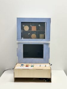
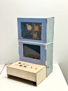
B. Conception and Design
Concept & Research
Existing interactive projects aim to provide audiences with positive feedback and a pleasant experience. Instead of following general principles of designing an interactive project, we decided to build an abnormal one that disconfirms expectations and leaves room for free exploration. The idea of using a vending machine to convey our concepts was derived from daily experience and observation. This part will be further elaborated in the conclusion part, as my understanding of the significance of our project was deepened through interacting with the audience.
Our preparatory research involved looking at an actual vending machine, and understanding how it functions and structures. We also read through some conceptual information including intuitive design (Intuitive Design by Interaction Design Foundation), counter-intuitive design (Counter-intuitive Ideas in Design, Aksu Ayberk), as well as useless conceptual designs (Katerina Kamprani’s projects).
Design Decisions
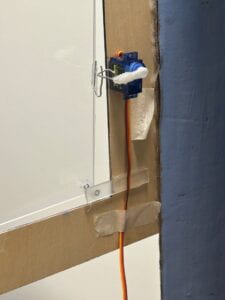
In general, we aimed to replicate the appearance of a vending machine (visually intuitive), so that the users could get a quick overview of what the project is about and what actions they could take. To fulfill this goal, we built a shelf that could fit in 6 cookies. We also had a glass door (with a lock controlled by a servo motor) and 6 corresponding buttons beneath.
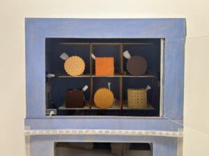
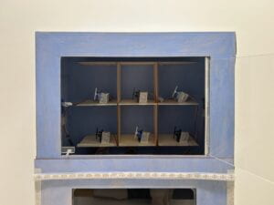
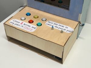
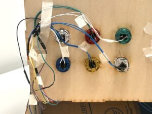
We chose fortune cookies as items to be “sold” because they have texts inside, so that different users will yield different outcomes, and the project would not become a one-time experience. However, when we at the point of 3D modeling, we failed to find free resources online, so we had to change the fortune cookie’s shape to normal ones and undertake the modeling ourselves.
Apart from the vending machine itself, we designed two small games that incorporated the communication between Arduino and Processing, which required mechanisms for physical input. For the first one, we decided to use two potentiometers to control the horizontal and vertical movement of the missing puzzle piece. And for the second one, we positioned a loudness sensor next to the screen to collect real-time volume for sound visualization.

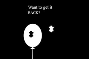

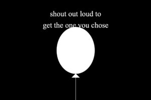
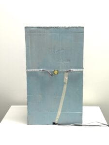
Moving on to the most crucial part, which was opening the window of our vending machine, we had many frustrations and went through a relatively long brainstorming process. Initially, we thought of letting the window drop off right after their volume reaches the threshold. However, it implied that the user had no choice but to follow our instructions step by step, which goes against with our concept. We then came up with the idea of placing the button on the back of our vending machine, and having a cue(“Get it from the back”) appear on the screen. But after meeting with Professor Inmi, we agreed on that we should minimize direct textual guidance and think of another way to lead them towards the back. Eventually, the music visualization recitation prompt reminded us the possibility of creating various patterns on the Neopixel LED strip, which contributed to our final decision of making the LEDs light up from the middle to both sides for multiple times, encouraging people to move towards the indicated direction.
User Testing
During the user testing phase, the majority of segments in our project were assembled. While the buttons and servo motors were functional, there were issues with the potentiometers and the sound sensor. Both of them had issues with unstable values. The reason for the former was mainly loose connections of the F/M wires. In addition, since the Arduino board that controlled servos and buttons was not connected to Processing, the screen showcased the puzzle and balloon from the very beginning of the interaction process. In other words, the screen and the actual progress was detached, and things did not appear in the right sequence, which made the users feel confused. Professor Gottfried suggested us to let Processing control two Arduinos simultaneously, which was challenging in terms of coding but turned out to be extremely helpful (details will be unfolded in the Fabrication & Production section).
Users also noted that we could reconsider the choice of sensors, as the sound sensor that we initially used is more sensitive in detecting sudden increases in volume, whereas the loudness sensor could better keep track of the variations in volume, which suits our sound visualization circumstance.
C. Fabrication and Production
Designing the interaction process: To fulfill our project goals, we designed a complete set of processes with multiple closely linked stages. This predetermined the complexity of our project, as we had to make sure that every single stage functions smoothly. The inspiration of the two games came from recitation prompts and examples in class, where I found the possible connections between Arduino and Processing appealing and leaves room for further exploration.
Code: We had four sketches in total (3 Arduino codes labeled as a, b, c, and one Processing code)
Arduino
a. Controls 6 buttons and 6 servos, make the other 5 servo motors rotate 150 degrees when a button is pressed. If any of the buttons are pressed(buttonState==1), the value “1” will be sent to Processing, indicating that the interaction with the first Arduino has finished.
b. Controls two potentiometers, a buzzer, a loudness sensor, a back button, and a servo(door lock). It consists of multiple stages and constantly sends values to Processing.
c. Controls the Neopixel LED Strip by reading values from the loudness sensor. Theoretically, this additional Arduino board is unnecessary, as it could be integrated with b. In practice, however, the code only functioned properly when run independently, and malfunctioned when combined with other sketches, so we had to run it separately.
Processing
To connect two Arduino boards through Processing, we first had to set up two serial ports, and modify rest of the code by noting the difference between arduino1 and 2. To create multiple stages and add transitions(a change in background or text) in between, we made use of several functions that we weren’t very familiar with, for example: frame count, boolean, and states.
One of the obstacles we encountered in the early stage was related to serial communication, as some values did not appear in serial monitor even though I wrote Serial.print(). I then learned that all the values that we intended to send to processing should be placed together as an array. In addition, the order in which they are listed also matters. For instance, Arduino_values[0] in Processing represents the first value to be printed in Arduino. Also, not only could actual sensor values be transmitted, digits representing stages could also be sent to trigger new actions. Another setback we met was getting NullPointerException errors after running the Processing sketch. The cause is forgetting to place the image in the right folder (corresponding to the sketch), so it failed to find and upload the image.
Circuits: To make sure that part b and c of the code mentioned previously worked, we wired the loudness sensor to both Arduino boards.
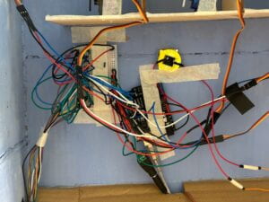
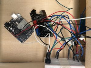
Laser cutting: We first drew a sketch and built a prototype beforehand to confirm its size and scale. Then we used makercase and cuttle.xyz to do further designs. Due to size limit, half of our project was made out of cardboard, and the other half(mainly the side facing users) was laser cut from wood and acrylic(the door for the vending machine).
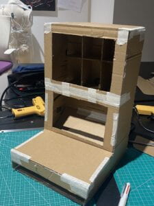
(prototype made from cardboard)
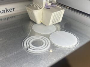
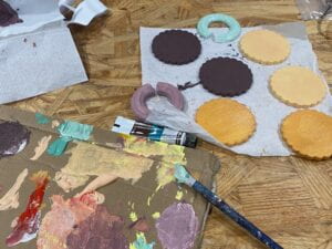
3D modeling & printing & painting: To make the cookies in our vending machine look more authentic, and enhance user’s experience, we 3D modeled and printed cookies and their fillings. We also added supports to the unstable structures in case of overhangs.
Assemble: Assembling the components was relatively simple compared to coding. However, it took us some time to organize the wires and reinforce the connection of the loose F/M cables as the legs kept falling out. Further more, since we embedded an iPad within our vending machine, we had to rearrange the inner structure and leave enough space for the cookies to fall out.
D. Conclusions
Goals and Audience Interaction
The objective of this project was to explore and observe how users perceive and interact with a project that does not always provide positive feedback. Although our designs provided them with a way to accomplish the ultimate goal, we intentionally left room for them to discover a short cut in the first place by moving around and engaging with our project. Audience interaction during the final presentation and IMA show varied from person to person. Some of them succeeded to discover the button on the back by following our cues, while others required slightly more information that we provided(such as verbal guidance). Although none of them managed to find out the button on their own without going through the whole process, users demonstrated a sense of resonance with our intention after we explained everything in detail.
Accomplishments and Reflection
As designers, we tend to assume that users will understand our instructions and interact with our project in the way we expect them to. However, in most cases, users perceive instruction effectiveness differently from how we do, which highlights the necessity of user testing. For our project in particular, there might be too many information provided at the same time, so the users will feel frustrated and unsure about where to begin. Just as they have mentioned: “There’s a clear boundary between trying to confuse the user and completely not knowing what to do.” This led me to reflect on ways to enhance the intuitiveness of our directions while still sticking close to our concept and principles.
A few adaptations we made were adding arrows that pointed to the back to complement the LED strip, and placing notices next to the buttons and potentiometers to assist them in making use of the interface.
Another issue that we confronted was the unstable sensor values. As our project involved measuring and visualizing volume, it relied heavily on an environment with relatively stable volume. Thus, to make sure that relevant components of our project functions normally, we had to modify the code(threshold values) every time we changed testing environments.
Further improvements
There are a few aspects that we would like to improve if given more time. First of all, based on user’s feedback, we should use an actual microphone to collect voice, or at least decorate the sensor to let user’s know where to shout to.
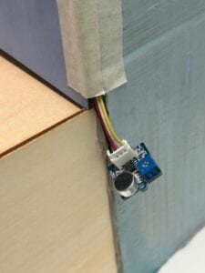
We also envisioned placing LEDs inside each column to illuminate the interior of the vending machine, as users had trouble seeing the mechanisms inside. Additionally, prior to interacting with the project, we could first set up a stage and provide some background context, giving the user a sense of what the project is about and what steps they should take. In terms of extending the concept of our project, we could reflect on the existing systems, critique their design and functions, and thereby elevate its overall impact.
Final remarks
Although we struggled from the iteration of coding and debugging, and dedicated countless nights to fix and refine our project, we were both content with the final product and our progress. Personally, there were moments of overwhelming frustration while learning Arduino and Processing, and despair when we had to undertake a project with great complexity. But fortunately, with the unconditional support from all the professors, fellows, LA’s and my partner Kitty, I managed to overcome numerous difficulties and consolidate my knowledge in coding.
E. Disassembly
F. Appendix
Video:
Link to the video: https://drive.google.com/file/d/1n0MD6sKq5rwg1RHBHYAmHTSuq6b82moZ/view?usp=sharing
Processing code:
import processing.serial.*;
Serial serialPort1; //first Arduino (servo motors, buttons)
Serial serialPort2; //second Arduino (potentiometers)
int NUM_OF_VALUES_FROM_ARDUINO1 = 1;
int NUM_OF_VALUES_FROM_ARDUINO2 = 5;  /* CHANGE THIS ACCORDING TO YOUR PROJECT /

 / This array stores values from Arduino */
int arduino_values1[] = new int[NUM_OF_VALUES_FROM_ARDUINO1];
int arduino_values2[] = new int[NUM_OF_VALUES_FROM_ARDUINO2];

int state1;
int state2;
float a;
float b;
PImage photo1, photo2;
PFont myFont;
boolean shoutDetected = false;
int oldFrameCount;

void setup() {
  size(1200, 800);
  printArray(Serial.list());
  // put the name of the serial port your Arduino is connected
  // to in the line below - this should be the same as you're
  // using in the "Port" menu in the Arduino IDE
  serialPort1 = new Serial(this, "/dev/cu.usbmodem1101", 9600);
  serialPort2 = new Serial(this, "/dev/cu.usbmodem1401", 9600);

  photo1 = loadImage("balloon.png");
  photo2 = loadImage("puzzle1.png");
  myFont = createFont("Times New Roman", 110);
}

void draw() {
  getSerialData();
  getSerialData2();
  if(arduino_values1[0] == 0){
    //interaction with the first Arduino is ongoing
    background(0);
    stroke(255);
    textFont(myFont);
    //textSize(50);
    textAlign(CENTER, CENTER);
    text("Get your fortune", width/2, height/2 - 65);
    text("by pressing ONE button", width/2, height/2 + 65);
  } else {
  state2 = arduino_values2[3];
  if (state2 == 1) {
    background(0);
    state1 = arduino_values2[0];
    float x = map(arduino_values2[1], 0, 1023, 100, 620);
    float y = map(arduino_values2[2], 0, 1023, -400, 250);
    image(photo1, x, y);
    image(photo2, 370, -50);
    stroke(255);
    textFont(myFont);
    textSize(60);
    text("Want to get it", 380, 120);
    textSize(map(sin(frameCount/3), -1, 1, 30, 80));
    text("BACK?", 380, 190);
    oldFrameCount = frameCount;
  } else if (state2 ==2) {
    background(0);
    stroke(255);
    textFont(myFont);
    text("shout out loud to", width/2, 170);
    text("get the one you chose", width/2, 260);
    if (frameCount >= oldFrameCount + 120) {
      //sound visualization
      float a = map(arduino_values2[4], 0, 70, 170, 1000);
      float b = a + 70;
      ellipse(width/2, height/2, a, b);
      triangle(width/2, 400+ b/2, width/2 - 30, 430+ b/2, width/2 + 30, 430+ b/2);
      stroke(255);
      strokeWeight(2);
      line(width/2, 430+ b/2, width/2, height);
      if (arduino_values2[4] >= 120) {
        shoutDetected = true;
      }
      if (shoutDetected == true) {
      background(255);
      fill(0);
      noStroke();
      triangle(350, 250, 200, 400, 350, 550);
      triangle(850, 250, 1000, 400, 850, 550);
      rect(350, 325, 150, 150);
      rect(700, 325, 150, 150);
        }
      }
    }
  }
}

void getSerialData() {
  while (serialPort1.available() > 0) {
    String in = serialPort1.readStringUntil(10);  // 10 = '\n'  Linefeed in ASCII
    if (in != null) {
      print("From Arduino: " + in);
      String[] serialInArray = split(trim(in), ",");
      if (serialInArray.length == NUM_OF_VALUES_FROM_ARDUINO1) {
        for (int i = 0; i < serialInArray.length; i++) {
          arduino_values1[i] = int(serialInArray[i]);
        }
      }
    }
  }
}

void getSerialData2() {
  while (serialPort2.available() > 0) {
    String in = serialPort2.readStringUntil(10);  // 10 = '\n'  Linefeed in ASCII
    if (in != null) {
      print("From Arduino: " + in);
      String[] serialInArray = split(trim(in), ",");
      if (serialInArray.length == NUM_OF_VALUES_FROM_ARDUINO2) {
        for (int i=0; i<serialInArray.length; i++) {
          arduino_values2[i] = int(serialInArray[i]);
        }
      }
    }
  }
}
Arduino b code:
#include <Servo.h>
#define DATA_PIN 3  // the pin connected to the strip's DIN
//back button
int pushButton0 = 2;
//microphone sensor
int microphone;
int buttonState0;
//servo
Servo myservo;

#define NOTE_G4 392
#define NOTE_E4 330
#define NOTE_C4 262
// Notes in the melody:
int melody[] = {
NOTE_G4, NOTE_E4, NOTE_C4, NOTE_E4, NOTE_G4
};
// Note durations: 4 = quarter note, 8 = eighth note, etc.:
int noteDurations[] = {
8, 8, 8, 8, 2
};
int state1 = 1;
int state2 = 1;
bool playMelodyOnce = false; // Flag to play the melody once

void setup() {
Serial.begin(9600);
  //back button
  pinMode(pushButton0, INPUT);
  //servo
  myservo.attach(9);
  myservo.write(90);
}

void loop() {
if (state1 == 1){
state11();
}
//if(state2 == 2){
//state22();
//}
//back button
  delay(1);
  buttonState0 = digitalRead(2);
  Serial.println(buttonState0);
  //when the back button is pressed, the door opens
  if (buttonState0 == 1) {
    while (buttonState0 == 0) {
      delay(10);
    }
     myservo.write(5);
  }
}

void state11(){
// Read sensor values
int sensor0 = analogRead(A4);
int sensor1 = analogRead(A1);
microphone = analogRead(A5);

// Send values to Processing
Serial.print(state1);
Serial.print(",");
Serial.print(sensor0);
Serial.print(","); // Put a comma between sensor values
Serial.print(sensor1);
Serial.print(",");
Serial.print(state2);
Serial.print(",");
Serial.print(microphone);

Serial.println(); // Add linefeed after sending the last sensor value
// Delay to avoid communication latency
delay(100);
if (!playMelodyOnce && sensor0 >= 526 && sensor0 <= 536 && sensor1 >= 544 && sensor1 <= 556) {
playMelodyOnce = true; // Set the flag to play the melody once
playMelody();
state2 = 2;
}
}

void playMelody() {
// Iterate over the notes of the melody
for (int thisNote = 0; thisNote < 5; thisNote++) {
// Calculate the note duration
int noteDuration = 1000 / noteDurations[thisNote];
tone(8, melody[thisNote], noteDuration);
// Set a pause between notes
int pauseBetweenNotes = noteDuration * 1.30;
delay(pauseBetweenNotes);

// Stop the tone playing
noTone(8);
}
}
Arduino a code:
#include <Servo.h>

// servos
Servo servo1;
Servo servo2;
Servo servo3;
Servo servo4;
Servo servo5;
Servo servo6;

// buttons
int pushButton1 = 2;
int pushButton2 = 3;
int pushButton3 = 4;
int pushButton4 = 5;
int pushButton5 = 6;
int pushButton6 = 7;
int buttonState1 = 0;
int buttonState2 = 0;
int buttonState3 = 0;
int buttonState4 = 0;
int buttonState5 = 0;
int buttonState6 = 0;

void setup() {
  //buttons
  pinMode(pushButton1, INPUT);
  pinMode(pushButton2, INPUT);
  pinMode(pushButton3, INPUT);
  pinMode(pushButton4,INPUT);
  pinMode(pushButton5,INPUT);
  pinMode(pushButton6,INPUT);
  // servos
  servo1.attach(8);
  servo2.attach(9);
  servo3.attach(10);
  servo4.attach(11);
  servo5.attach(12);
  servo6.attach(13);
  servo1.write(5);
  servo2.write(5);
  servo3.write(5);
  servo4.write(5);
  servo5.write(5);
  servo6.write(5);
  Serial.begin(9600);
}

void loop() {
  // read buttonState
  buttonState1 = digitalRead(pushButton1);
  buttonState2 = digitalRead(pushButton2);
  buttonState3 = digitalRead(pushButton3);
  buttonState4 = digitalRead(pushButton4);
  buttonState5 = digitalRead(pushButton5);
  buttonState6 = digitalRead(pushButton6);

  if (buttonState1 == 1) {
    while (buttonState1 == 0) {
      delay(10);
    }
    delay(1000);
    servo1.write(5);
    servo2.write(150);
    servo3.write(150);
    servo4.write(150);
    servo5.write(150);
    servo6.write(150);
  } else if (buttonState2 == 1) {
    while (buttonState2 == 0) {
      delay(10);
    }
    delay(1000);
    servo1.write(150);
    servo2.write(5);
    servo3.write(150);
    servo4.write(150);
    servo5.write(150);
    servo6.write(150);
  } else if (buttonState3 == 1) {
    while (buttonState3 == 0) {
      delay(10);
    }
    delay(1000);
    servo1.write(150);
    servo2.write(150);
    servo3.write(5);
    servo4.write(150);
    servo5.write(150);
    servo6.write(150);
  } else if (buttonState4 == 1) {
    while (buttonState4 == 0) {
      delay(10);
    }
    delay(1000);
    servo1.write(150);
    servo2.write(150);
    servo3.write(150);
    servo4.write(5);
    servo5.write(150);
    servo6.write(150);
  } else if (buttonState5 == 1) {
    while (buttonState5 == 0) {
      delay(10);
    }
    delay(1000);
    servo1.write(150);
    servo2.write(150);
    servo3.write(150);
    servo4.write(150);
    servo5.write(5);
    servo6.write(150);
  } else if (buttonState6 == 1) {
    while (buttonState6 == 0) {
      delay(10);
    }
    delay(1000);
    servo1.write(150);
    servo2.write(150);
    servo3.write(150);
    servo4.write(150);
    servo5.write(150);
    servo6.write(5);
  }

  if (buttonState1 == 1 || buttonState2 == 1 || buttonState3 == 1 || buttonState4 == 1 || buttonState5 == 1 || buttonState6 == 1){
    Serial.print("1");
    Serial.println();
  }
}
Arduino c code:
#include <FastLED.h>
#define NUM_LEDS 60
#define DATA_PIN 3  // the pin connected to the strip's DIN
CRGB leds[NUM_LEDS];
int middle = NUM_LEDS / 2;
int microphone;
bool ledState = false;
//int pushButton0 = 2;
//int buttonState0;

void setup() {
  Serial.begin(9600);
  FastLED.addLeds<NEOPIXEL, DATA_PIN>(leds, NUM_LEDS);
  fill_solid(leds, NUM_LEDS, CRGB::Black);
  FastLED.show();
 // pinMode(pushButton0, INPUT);
}

void loop() {
 // buttonState0 = digitalRead(2);
  //Serial.println(buttonState0);
  microphone = analogRead(A5);
  Serial.println(microphone);

    if (microphone >= 160 && ledState == false) {
      lightUpLED();
      ledState = true;
    } else if (microphone >= 160 && ledState == true) {
      lightUpLED();
    } else if (microphone < 160 && ledState == true) {
      lightUpLED();
    }
}

void lightUpLED() {
  ledState = true;
  for (int i = 0; i <= middle; i = i + 1) {
    leds[middle - i] = CRGB(241, 247, 75);
    leds[middle + i] = CRGB(241, 247, 75);
    FastLED.show();
    delay(250);
  }
  fill_solid(leds, NUM_LEDS, CRGB::Black);
  FastLED.show();
  delay(300);
}
