Interaction Lab: Midterm Project

PENTA-MUSICAL LAMP – CALVIN LIN – PROFESSOR GOTTFRIED

CONTEXT AND SIGNIFICANCE:

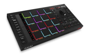
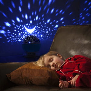
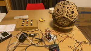
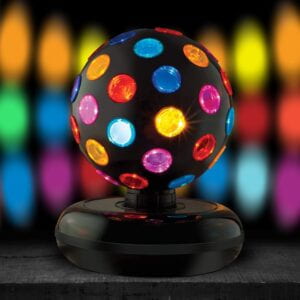
The inspiration originated from my love for music and clubbing. As a child, I often had a lamp, be it a lava lamp or something else. There was always a lamp or some sort of light that was placed next to my bed. Our original idea was to make a lamp. We wanted the aesthetic to be the main part of it. But simply a lamp to me was not interactive enough. A simple lick or pull was not how I defined interaction to be. I wanted the lamp to have more than just light. This made me think about disco balls/LED lights at clubs. The lights changed with every movement, sound, and music that was played. So that inspired me to add a beat pad or a D.J. pad on top of the idea I already had. Further planning later, our idea solidified into a lamp that was A: able to change colors, B: able to produce sound and musical notes with the corresponding button that was pressed, C: the light and sound are correlated with each other, and lasting D: able to spin and produce reflections of the lights coming out from the ball. Just like music, there are no set variables. That is how I defined interaction. Users will have the opportunity to play any songs they enjoy with the notes provided to them. Since the buttons are only limited to 9, the notes that they will have access to will be limited. But there are infinite possibilities they can do with the notes provided for them. This matches with my definition of interaction as the user are not going on a set path created for them, but rather can use the project I made and play as they wish. I do not classify my project as unique, as the concept of lamp and music has definitely already been invented. But many times, we do not see the combination of music and lamp together. It is either a lamp for light or music for music. As we often associate a lamp with something quiet rather than an instrument. I believe my project is defiantly for children, individuals who love playing music (aka piano), or even people who can go to clubs during the pandemic. So that they can make a mini club at their own home and D.J. away. Even without the music part of it, the reflection of the lamp is soothing and relaxing to look at. This can help children who are scared at night to have some light and something to look at before they fall asleep. 


CONCEPTION AND DESIGN:

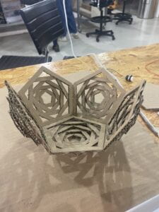
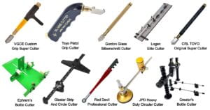
Being a former art student, I believed in the wow concept. Even before the user even has the opportunity to use it, I want them to be wowed just by looking at the fabrication of it. I relate this type of idea to cooking, you taste with your eyes before your mouth. It must be pleasant to the eyes, in order to draw the user’s interest in the project. Children choose toys not because they think this might be fun, how would they know before they even try them? That is because the toy is pleasing to them and their imagination. They are eager to try something that is aesthetic rather than something that looks plain and simple. Having this in mind, we made sure to put emphasis on the design of the lamp. Cardboard can many times seem flat and unappealing. So one of our challenges was to make it more 3-dimensional. We achieved this by layering the cardboard on top of each other. So instead of one side of the lamp just be a simple pentagon. We added 4 more layers of pentagons of different sizes on top of the original one. This will be explained more in-depth in the next section, where I will discuss the fabrication part of my project. Ultimately for our project, we choose to use cardboard for a couple of reasons. Firstly, it was easily obtainable. We were able to find cardboard pieces from the cardboard recyclable in Room 826. To our surprise, we even found a very beautiful circular platform from it. Secondly, cardboard is very flexible. Even if you made a mistake it can be quite easily fixed. Thirdly, cardboard is quite easy to work with compared to other materials such as metal or glass. Lastly, cardboard quite frankly the own material we have learned to use.  A lot of other materials require a lot of other tools to fully use them to their max compacity. For example, for wood, you need bigger tools to make it into the shape and design you want. Glass and metal are both similar, they require tools sometimes not accessible to us. That was why we figured cardboard would be the best material used for this project. If we did use wood, I feel like the final project would have more depth and a wow factor to it. But the level of difficulty will also increase. 
     

IT IS EVERYWHERE!    

WOOD TOOLS:

GLASS TOOLS:
FABRICATION AND PRODUCTION:

This was our original plan:
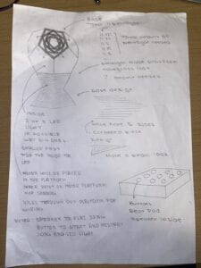
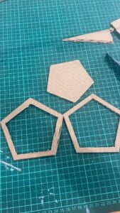
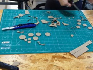
Looking back, the most tedious and time-consuming part of our project was definitely making the design of the lamp. We had to cut out a total of 55 pentagons: 11 XXL, 11XL, 11L, 11M, and 11S. This made up the basis of our light design. Cutting them took a very long time. Especially since me and my partner are both perfectionists, a simple mistake we had to throw it away and start over. So I consider one of our failures was just wasting some of the cardboard we threw away because it did not meet our expectations. In another way, I felt that because of this tedious mindset, our project turned out really nice aesthetically. 
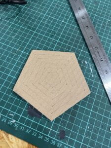
         

After completing the lamp shape, we did a light test at home. We did this simply by putting a phone flashlight under the lamp. We wanted to see how the light would go through the shapes, just in case we needed to make any adjustments. 

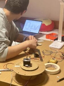
We were quite satisfied with the result and we moved on to the coding part of the project. We started out by testing the motor. We used the same steps and codes as we did in recitation 4. We made it so that it spun at a slower rate. At first, we programmed it to spin one way at a speed of 30. Then we realized that making it spin only one way was not gonna work. As the wires of the LED light will get tangled up and become unfunctional. In the end, we made it turn 180 before going back and repeating. Although the motor did give us a lot of trouble. We had to in total switch out 4 motors. We did not know the exact issue, but we had a few guesses. Some issues included the H-bridge being fried, a broken motor, the code having too much stuff on it, the motor receiving the wrong amounts of power, and the Arduino breaking. It was quite a big headache, to say the least. We then added the 3D-printed motor platform, completing the motor step of the project. 
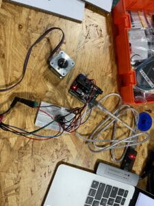
         

After the motor, we started working on the light for the project. We started with one button and then increased it bit by bit. This was to ensure we catch any flaws or errors in the code as we worked on it. We made sure that whenever a button was pressed, the LED associated with it also lit up. 
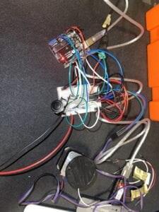
                       

After completing the LED light, we started to add the buttons to the project. Our goal was for each button to have a specific piano note attached to it. We did this through the pitch library. 
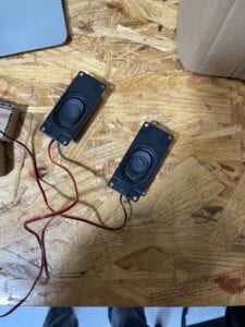
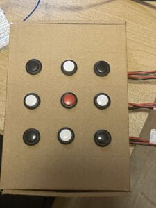
After completing the buzzer and making it work, we were close to finishing the project, so we started doing the final touch of the project. We made the last component of our project, which was the beat pad. We soldered 9 buttons and cut holes into a box that we found. The challenging part of this portion was soldering the buttons. We messed up a few times when we held the soldering iron too close to the plastic part of the button, which caused the metal piece to become unstable. After finishing soldering all of them we placed them into the cardboard box. We cut holes from the inside for the wires to come out. To organize all the wires, we tapped each wire GND and 5V together. This way we will not get mixed up with each wire. 
         

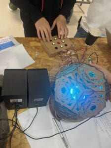
As we were working on the project, we discovered that the LED lights were not bright enough. We had to find something more bright for the effects to be there. Thankfully, we were able to receive a Neo-Pixel Ring from Professor Margaret. With the Neo-Pixel Ring, the light was finally bright enough to show the lamp pattern. We hot glued the Neo-Pixel Ring onto a circular cardboard. Then we hot glued that onto the 3D printed platform. Since our platform already had holes throughout it. We just put the wires of the Neo-Pixel Ring through them and connected them to the breadboard. 
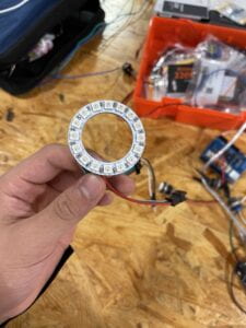
    

This was a test we did with the Neo-Pixel Ring. The effects were quite good. 

For the final touches, all we had to do was connect the wires together. In this case, we had to use a different computer and Arduino for the motor. The motor seemed to not want to work with the rest of the code so we separated the motor code from the rest of the code. 
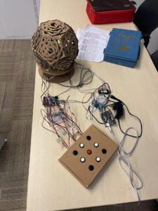
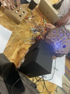
During the user testing, it worked quite well. Everyone seemed to enjoy it and had a fantastic time playing with it. The only downside during the whole process was that the room was too bright, so sadly they were not able to see the reflection of the light on the wall. There were some really good suggestions. The first was about the sound of the project. Since the tone was quite quiet compared to the rest of the room which was quite loud. The user was not able to fully hear the notes. We solved this on the spot by renting a speaker from the resource center. It did a great job amplifying the sound of the note. Another suggestion made by professor Andy was to make a box that covered all the wires. We thought that it was a great suggestion and later inputted that comment into our project. 
         

CONCLUSIONS:

The goal of our project was to create an item that inspired people to play music or even use it as a substitute for clubbing. It is cheaper and safer compared to clubbing. For children, it will inspire them to play music. Furthermore, it can act as a guardian for kids who are afraid of the light. Act as their little lamp and source of light at night. Our project, in my opinion, has many forms of interaction. There is a visual interaction of the artwork. Users have the ability to play any notes, with any combination that likes. At the same time, they are able to hear it and see it physically change through color and sound. My definition of interaction is something with no set variable, with the user creating their own pathway. Rather than going down a specific path, we creators made for them. Freedom to me is the essence of the interaction. If we had more time there are some parts of the project that I would have wanted to work more on. Firstly, I think the sound of the project could have been made smoother. When the user was testing it out on the loudspeaker. The sound was very scratchy and not clean. Could have been the code or it could have been the speaker. Secondly, I think it would have been cool if I had a set of song playlists playing in the background of the project. When the user clicks a button it will generate a random song from our playlist. From there they can add to it with the notes on the beat pad. Making it more D.J.-like. But they are always able to play a song with their phone and do it that way. Lastly, I would organize the wires more. The box that was used to cover the wires, in my opinion, was too big and close to the lamp itself. I think in a way it took away from the aesthetic part of the project. I think that the important value that I took away from this project was that there are always more answers to the problem. If one way does not work out try another way. Have your mind and options open when you make the project. There are bound to challenge you to make a project, but be open to mistakes and change according to them. I think my biggest accomplishment was being able to create something sophisticated at the start of this class. Now looking forward, I want to make something that surpasses this for my final project. 

What a cheap option that satisfies both your and your child’s interest, look at Penta-Musical Lamp. Covid like darkness is all around us. We only feel safe at home. Let Penta-Musical Lamp be the light to your child’s darkness at night. Let it be the tool for you to transition to the long-awaited clubs that have closed down. Everyone’s musical journey starts somewhere, let Penta-Musical Lamp be that start of the journey. 

ANNEX:

POSTER: 
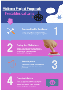
MATERIAL: 

  • 42STH33-0404AC stepper motor
  • L293D chip (H-bridge)
  • Power jack
  • 12 VDC power supply
  • USB protector
  • Motor Platform
  • Neo-Pixel Ring
  • Wires
  • 9 Buttons
  • Arduino Uno
  • Breadboard
  • Pingpong Ball
  • Cardboard
  • Soldering Iron/Metal 
  • Buzzer
  • Speaker
  • Electrical Clamps

CODE: NEO-PIXEL RING, BUTTON, AND TONE

#include “pitches.h”
#include <Adafruit_NeoPixel.h>
#ifdef __AVR__
#include <avr/power.h> // Required for 16 MHz Adafruit Trinket
#endif
// Which pin on the Arduino is connected to the NeoPixels?
// On a Trinket or Gemma we suggest changing this to 1:
#define LED_PIN 6
// How many NeoPixels are attached to the Arduino?
#define LED_COUNT 24
Adafruit_NeoPixel strip(LED_COUNT, LED_PIN, NEO_GRB + NEO_KHZ800);
int buzzer = 12;
int button1 = 2; // Button 1,4,7 are connected to first LED light // Button 1 will be connected to A4 note
int button4 = 5; // Button 4 will be connected to D4 note
int button7 = 9; // Button 7 will be connected to G4 note
int button2 = 3; // Button 2,5,8 are connected to second LED light // Button 2 will be connected to B4 note
int button5 = 7; // Button 5 will be connected to E4 note
int button8 = 10; // Button 8 will be connected to ?4 note
int button3 = 4; // Button 3,6,9 are connected to third LED light // Button 2 will be connected to C4 note
int button6 = 8; // Button 6 will be connected to F4 note
int button9 = 11; // Button 9 will be connected to ?4 note
int buttonState1 = 0;
int buttonState2 = 0;
int buttonState3 = 0;
int buttonState4 = 0;
int buttonState5 = 0;
int buttonState6 = 0;
int buttonState7 = 0;
int buttonState8 = 0;
int buttonState9 = 0;
void setup() {
pinMode(button1, INPUT_PULLUP);
pinMode(button2, INPUT_PULLUP);
pinMode(button3, INPUT_PULLUP);
pinMode(button4, INPUT_PULLUP);
pinMode(button5, INPUT_PULLUP);
pinMode(button6, INPUT_PULLUP);
pinMode(button7, INPUT_PULLUP);
pinMode(button8, INPUT_PULLUP);
pinMode(button9, INPUT_PULLUP);
pinMode(buzzer, OUTPUT);
#if defined(__AVR_ATtiny85__) && (F_CPU == 16000000)
clock_prescale_set(clock_div_1);
#endif
// END of Trinket-specific code.
strip.begin(); // INITIALIZE NeoPixel strip object (REQUIRED)
strip.show(); // Turn OFF all pixels ASAP
strip.setBrightness(100); // Set BRIGHTNESS to about 1/5 (max = 255)
// initialize the serial port:*/
Serial.begin(9600);
}
void loop() {
Serial.println(“Loop”);
// Button 1:
buttonState1 = digitalRead(button1);
buttonState2 = digitalRead(button2);
buttonState3 = digitalRead(button3);
buttonState4 = digitalRead(button4);
buttonState5 = digitalRead(button5);
buttonState6 = digitalRead(button6);
buttonState7 = digitalRead(button7);
buttonState8 = digitalRead(button8);
buttonState9 = digitalRead(button9);
if(buttonState1 == LOW){
tone(buzzer, 440);
strip.clear(); // Set all pixels in RAM to 0 (off)
for(int c = 0; c < strip.numPixels(); c += 1){
strip.setPixelColor(c, strip.Color(255, 0, 0));
}
strip.show(); // Update strip with new contents
}elseif(buttonState2 == LOW){
tone(buzzer, 494);
strip.clear(); // Set all pixels in RAM to 0 (off)
for(int c = 0; c < strip.numPixels(); c += 1){
strip.setPixelColor(c, strip.Color(0, 255, 0));
}
strip.show(); // Update strip with new contents
}elseif(buttonState3 == LOW){
tone(buzzer, 262);
strip.clear(); // Set all pixels in RAM to 0 (off)
for(int c = 0; c < strip.numPixels(); c += 1){
strip.setPixelColor(c, strip.Color(0, 0, 255));
}
strip.show(); // Update strip with new contents
}elseif(buttonState4 == LOW){
tone(buzzer, 294);
strip.clear(); // Set all pixels in RAM to 0 (off)
for(int c = 0; c < strip.numPixels(); c += 1){
strip.setPixelColor(c, strip.Color(255, 255, 0));
}
strip.show(); // Update strip with new contents
}elseif(buttonState5 == LOW){
tone(buzzer, 330);
strip.clear(); // Set all pixels in RAM to 0 (off)
for(int c = 0; c < strip.numPixels(); c += 1){
strip.setPixelColor(c, strip.Color(0, 255, 255));
}
strip.show(); // Update strip with new contents
}elseif(buttonState6 == LOW){
tone(buzzer, 349);
strip.clear(); // Set all pixels in RAM to 0 (off)
for(int c = 0; c < strip.numPixels(); c += 1){
strip.setPixelColor(c, strip.Color(255, 0, 255));
}
strip.show(); // Update strip with new contents
}elseif(buttonState7 == LOW){
tone(buzzer, 392);
strip.clear(); // Set all pixels in RAM to 0 (off)
for(int c = 0; c < strip.numPixels(); c += 1){
strip.setPixelColor(c, strip.Color(255, 255, 255));
}
strip.show(); // Update strip with new contents
}elseif(buttonState8 == LOW){
tone(buzzer, 277);
strip.clear(); // Set all pixels in RAM to 0 (off)
for(int c = 0; c < strip.numPixels(); c += 1){
strip.setPixelColor(c, strip.Color(100, 100, 255));
}
strip.show(); // Update strip with new contents
}elseif(buttonState9 == LOW){
tone(buzzer, 311);
strip.clear(); // Set all pixels in RAM to 0 (off)
for(int c = 0; c < strip.numPixels(); c += 1){
strip.setPixelColor(c, strip.Color(100, 255, 100));
}
strip.show(); // Update strip with new contents
}else{
noTone(buzzer);
}
// Button 1:
buttonState1 = digitalRead(button1);
if(buttonState1 == LOW) // D1 Port
{
tone(buzzer, 440);
}
// Butoon 2:
buttonState2 = digitalRead(button2);
if(buttonState2 == LOW) // D2 Port
{
tone(buzzer, 494);
}
// Button 3:
buttonState3 = digitalRead(button3);
if(buttonState3 == LOW) // D3 Port
{
tone(buzzer, 262);
}
// Button 4:
buttonState4 = digitalRead(button4);
if(buttonState4 == LOW) // D4 Port
{
tone(buzzer, 294);
}
// Button 5:
buttonState5 = digitalRead(button5);
if(buttonState5 == LOW) // D5 Port
{
tone(buzzer, 330);
}
// Button 6:
buttonState6 = digitalRead(button6);
if(buttonState6 == LOW) // D6 Port
{
tone(buzzer, 349);
}
// Button 7:
buttonState7 = digitalRead(button7);
if(buttonState7 == LOW) // D7 Port
{
tone(buzzer, 392);
}
// Button 8:
buttonState8 = digitalRead(button8);
if(buttonState8 == LOW) // D8 Port
{
tone(buzzer, 277);
}
 
// Button 9:
buttonState9 = digitalRead(button9);
if(buttonState9 == LOW) // D9 Port
{
tone(buzzer, 311);
}
}
// Neo-Pixel Library
void colorWipe(uint32_t color, int wait) {
for(int i = 0; i < strip.numPixels(); i++){ // For each pixel in strip…
strip.setPixelColor(i, color); // Set pixel’s color (in RAM)
strip.show(); // Update strip to match
delay(wait); // Pause for a moment
}
}
// Theater-marquee-style chasing lights. Pass in a color (32-bit value,
// a la strip.Color(r,g,b) as mentioned above), and a delay time (in ms)
// between frames.
void theaterChase(uint32_t color, int wait) {
for(int a = 0; a < 10; a++){ // Repeat 10 times…
for(int b = 0; b < 3; b++){ // ‘b’ counts from 0 to 2…
strip.clear(); // Set all pixels in RAM to 0 (off)
// ‘c’ counts up from ‘b’ to end of strip in steps of 3…
for(int c = b; c < strip.numPixels(); c += 3){
strip.setPixelColor(c, color); // Set pixel ‘c’ to value ‘color’
}
strip.show(); // Update strip with new contents
delay(wait); // Pause for a moment
}
}
}
// Rainbow cycle along whole strip. Pass delay time (in ms) between frames.
void rainbow(int wait) {
// Hue of first pixel runs 5 complete loops through the color wheel.
// Color wheel has a range of 65536 but it’s OK if we roll over, so
// just count from 0 to 5*65536. Adding 256 to firstPixelHue each time
// means we’ll make 5*65536/256 = 1280 passes through this loop:
for(long firstPixelHue = 0; firstPixelHue < 5 * 65536; firstPixelHue += 256){
// strip.rainbow() can take a single argument (first pixel hue) or
// optionally a few extras: number of rainbow repetitions (default 1),
// saturation and value (brightness) (both 0-255, similar to the
// ColorHSV() function, default 255), and a true/false flag for whether
// to apply gamma correction to provide ‘truer’ colors (default true).
strip.rainbow(firstPixelHue);
// Above line is equivalent to:
// strip.rainbow(firstPixelHue, 1, 255, 255, true);
strip.show(); // Update strip with new contents
delay(wait); // Pause for a moment
}
}
// Rainbow-enhanced theater marquee. Pass delay time (in ms) between frames.
void theaterChaseRainbow(int wait) {
int firstPixelHue = 0; // First pixel starts at red (hue 0)
for(int a = 0; a < 30; a++){ // Repeat 30 times…
for(int b = 0; b < 3; b++){ // ‘b’ counts from 0 to 2…
strip.clear(); // Set all pixels in RAM to 0 (off)
// ‘c’ counts up from ‘b’ to end of strip in increments of 3…
for(int c = b; c < strip.numPixels(); c += 3){
// hue of pixel ‘c’ is offset by an amount to make one full
// revolution of the color wheel (range 65536) along the length
// of the strip (strip.numPixels() steps):
int hue = firstPixelHue + c * 65536L / strip.numPixels();
uint32_t color = strip.gamma32(strip.ColorHSV(hue)); // hue -> RGB
strip.setPixelColor(c, color); // Set pixel ‘c’ to value ‘color’
}
strip.show(); // Update strip with new contents
delay(wait); // Pause for a moment
firstPixelHue += 65536 / 90; // One cycle of color wheel over 90 frames
}
}
}
 
CODE: MOTOR

#include <Stepper.h>

const int stepsPerRevolution = 100; // change this to fit the number of steps per revolution
// for your motor

// initialize the stepper library on pins 8 through 11:
Stepper myStepper(stepsPerRevolution, 8, 9, 10, 11);

void setup() {
// set the speed at 60 rpm:
myStepper.setSpeed(10);
// initialize the serial port:
Serial.begin(9600);
}

void loop() {
// step one revolution in one direction:
myStepper.step(stepsPerRevolution);

// step one revolution in the other direction:
myStepper.step(-stepsPerRevolution);

PITCHES:

#define NOTE_B0 31
#define NOTE_C1 33
#define NOTE_CS1 35
#define NOTE_D1 37
#define NOTE_DS1 39
#define NOTE_E1 41
#define NOTE_F1 44
#define NOTE_FS1 46
#define NOTE_G1 49
#define NOTE_GS1 52
#define NOTE_A1 55
#define NOTE_AS1 58
#define NOTE_B1 62
#define NOTE_C2 65
#define NOTE_CS2 69
#define NOTE_D2 73
#define NOTE_DS2 78
#define NOTE_E2 82
#define NOTE_F2 87
#define NOTE_FS2 93
#define NOTE_G2 98
#define NOTE_GS2 104
#define NOTE_A2 110
#define NOTE_AS2 117
#define NOTE_B2 123
#define NOTE_C3 131
#define NOTE_CS3 139
#define NOTE_D3 147
#define NOTE_DS3 156
#define NOTE_E3 165
#define NOTE_F3 175
#define NOTE_FS3 185
#define NOTE_G3 196
#define NOTE_GS3 208
#define NOTE_A3 220
#define NOTE_AS3 233
#define NOTE_B3 247
#define NOTE_C4 262
#define NOTE_CS4 277
#define NOTE_D4 294
#define NOTE_DS4 311
#define NOTE_E4 330
#define NOTE_F4 349
#define NOTE_FS4 370
#define NOTE_G4 392
#define NOTE_GS4 415
#define NOTE_A4 440
#define NOTE_AS4 466
#define NOTE_B4 494
#define NOTE_C5 523
#define NOTE_CS5 554
#define NOTE_D5 587
#define NOTE_DS5 622
#define NOTE_E5 659
#define NOTE_F5 698
#define NOTE_FS5 740
#define NOTE_G5 784
#define NOTE_GS5 831
#define NOTE_A5 880
#define NOTE_AS5 932
#define NOTE_B5 988
#define NOTE_C6 1047
#define NOTE_CS6 1109
#define NOTE_D6 1175
#define NOTE_DS6 1245
#define NOTE_E6 1319
#define NOTE_F6 1397
#define NOTE_FS6 1480
#define NOTE_G6 1568
#define NOTE_GS6 1661
#define NOTE_A6 1760
#define NOTE_AS6 1865
#define NOTE_B6 1976
#define NOTE_C7 2093
#define NOTE_CS7 2217
#define NOTE_D7 2349
#define NOTE_DS7 2489
#define NOTE_E7 2637
#define NOTE_F7 2794
#define NOTE_FS7 2960
#define NOTE_G7 3136
#define NOTE_GS7 3322
#define NOTE_A7 3520
#define NOTE_AS7 3729
#define NOTE_B7 3951
#define NOTE_C8 4186
#define NOTE_CS8 4435
#define NOTE_D8 4699
#define NOTE_DS8 4978
 

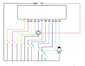
CIRCUIT DIAGRAM: NEO-PIXEL RING, BUTTON, AND TONE
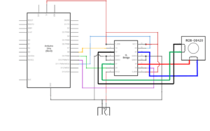
CIRCUIT DIAGRAM: MOTOR
WORK-CITED:

Pictures: 

Admin. “12 Types of Wood Cutting Tools and Their Uses [with Pictures & Names].” Engineering Learn, 28 Nov. 2021, https://engineeringlearn.com/12-types-of-wood-cutting-tools-and-their-uses-with-pictures-names/.

Admin. “Types of Glass Cutting Tools and Their Uses [with Pictures].” Engineering Learn, 18 Nov. 2021, https://engineeringlearn.com/types-of-glass-cutting-tools-and-their-uses-with-pictures/.

Amazon.com: Kicko Spinning Disco Ball with LED Lights – for Parties … https://www.amazon.com/Kicko-Spinning-Disco-Ball-Lights/dp/B09XB672RW.

General Kinematics. “What Is Cardboard Made Of.” General Kinematics, General Kinematics, 7 Sept. 2021, https://www.generalkinematics.com/blog/the-life-cycle-of-cardboard/.

“MPC Studio.” Music Production Hardware & Software, https://www.akaipro.com/mpcstudio.

“Nightclub.” Wikipedia, Wikimedia Foundation, 19 Sept. 2022, https://en.wikipedia.org/wiki/Nightclub.

“兒童燈Star Projector Lamp Children Bedroom Led Night Light Baby Lamp Decor Rotating Starry Nursery Moon Galaxy Projector Table Lamp.” 燈神世界數碼, https://shop.price.com.hk/light/product/874327.

Code:

/**

* An Neo-Pixel Ring that turns ON and OFF

* This was adapted from the tutorial found here:

* https://www.arduino.cc/reference/en/libraries/adafruit-neopixel/

* https://github.com/adafruit/Adafruit_NeoPixel

[…]

*/
Recitation 4: Actuators and Mechanisms

Step 1: Build the circuit

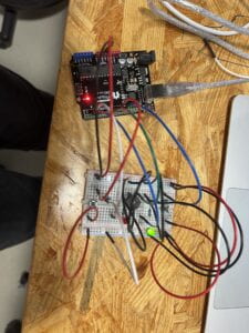
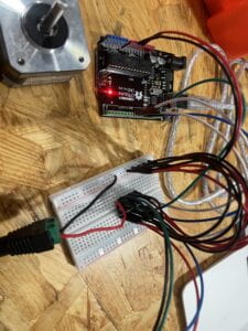
The stepper motor circuit, in my opinion, was quite easy to build. As usual, I plugged my adaptor into my computer along with the cable that connects my computer to the Arduino UNO. The only difference this time was that I used a USB Protector since we are working with higher voltage. As the voltage gets higher, the risk of damaging your computer increases. I first placed the H bridge on my breadboard. I connected a wire from 5V to the positive port and a wire from GND to the negative port of the breadboard. This will allow positive and negative energy to run throughout the breadboard.

Starting with the top left port of the H bridge. I connected the first port to the positive end of the breadboard. Going down, I then connected a wire from D8 to the second port. In the third port, I connected the black wire on my motor to it. Ports 4 and 5, I connected them with a wire to the negative end of the breadboard. Port 6 I connected the green wire on the motor to it. For port 7, I connected it to D9 with a wire. Lastly, for port 8, I connected it to the positive end of the power jack to it. 

Starting from the top right of the H bridge. I connected port 16 to the positive end of the breadboard. For port 15, I connected it to D11 of the Arduino. Making our way down, port 14 was connected to the blue wire of the motor. Port 13 and 12, were connected to the negative end of the breadboard. Furthermore, for port 11 I connected it to the red wire of the motor. Port 10 was connected to D10 on the Arduino Uno. Lastly, port 9 was connected to the positive end of the breadboard. 

The power jack was also connected to a 12 VDC power supply, as an external power supply. As simply using the computer as a power source, was not enough to show the full capacity of the motor. 


Step 2: Build a cardboard mechanism!

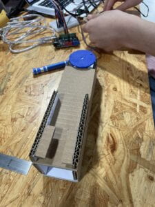
This step was really fun. We first glued the template onto our cardboard. We cut the cardboard according to the lines on the template. After cutting out all parts of the project, we heated up our hot glue gun. We glued everything according to the instructions listed on them. After completing it, we placed the motor on one end of the mechanism and we used a rivet to help the rotating link from staying on the shaft adaptor. 

Step 3: Personalize it

For our mechanism, we wanted to tell a story of a person eating ice cream on a hot summer day.  We first drew an ice cream cone on cardboard and cut it out. We added some color to it to make it look more appetizing. For our program, we made sure to delay the motor for a good amount of time between each lick the user takes. We did not want the motor to go too fast, when eating ice cream there will be a period between each lick or bite. 

Documentation Questions: 

Question 1: Choose an art installation mentioned in the reading ART + Science NOW, Stephen Wilson (Kinetics chapter). Post your thoughts about it and make a comparison with the work you did during this recitation. How do you think that the artist selected those specific actuators for his project?

Answer 1: The project that attracted my attention was Daniel Palacios Jimenez’s Waves, 2006. The use of the motor was similar to what we did in recitation, but the speed of the motor would have probably spun faster compared to our motor. That is the case to create the illusion of solid shapes with the rope spinning at a certain speed. Similarly, the motor is used in a way to tell a story but in this case rather than a cardboard telling the story, Jimenez used a rope to tell it. Ropes are all around us. When I was a child I would put something that has weight in between two strings and spin it. When I let go it will make something similar to what he did in this project. He might have got his inspiration from such a small and simple things kids usually do with necklace or strings. The motor is used in this case as a replication of the hand motion or a substitute/start for the system. 

Question 2: What kind of mechanism would you be interested in building for your midterm project? Explain your idea using a sketch (conceptual or technical) with a list of materials that you plan to use. Include details about the ways that you expect the user to embrace in a physical interaction with your project. In particular, explain how would your motor (or motors) with a mechanism will be different than using an animation on a digital screen.

Answer 2: The mechanism that I am interested in building for my midterm is a lampshade and a beat pad. The lampshade will be a geometric pentagon. It will be on a platform, with a motor inside the platform. The motor will also have a platform on top of it in which the LED lights will sit and spin on it. The LED light and motor will be connected buttons. Each button will have a correlating LED light to it. Also, each of the buttons will also have a correlating sound that goes along with it. The buttons and buzzer will be in together to make up the beat pad. There will also be a middle box, where we organize the Arduino and wires. The user will use the beat pad to create any notes or songs they prefer, while doing so they will be able to physically hear the transition between sounds and LED lights.    Physically the motor will be mainly spinning one way at a certain speed. The motor’s main purpose in my project is to spin the LED lights. Compared to a screen, it will just tell me it’s going left or right. I will physically be able to see light moving and changing. 

Interaction Lab – Individual Proposal Project

Midterm Proposal:

Title: Penta-Musical Lamp

Group Members: Calvin Lin & Jason Li

My inspiration originates from my piano class, my love for music, and ironically a disco ball. The intended audience includes all ages or who have an interest in music and visual artworks. Users will be able to play simple notes or even songs while enjoying a LED light show, making this project an alternative for clubbing. 

Materials:

  • 42STH33-0404AC stepper motor
  • L293D chip (H-bridge)
  • Power jack
  • 12 VDC power supply
  • USB protector
  • Motor Platform
  • 3 LED Lights
  • Wires
  • 9 Buttons
  • Arduino Uno
  • Breadboard
  • Pingpong Ball
  • Cardboard
  • 1k Resistor
  • 220 Resister 
  • Soldering Iron/Metal 
  • Buzzer

References:


Sketch/Diagram:

Block-Diagram Link

Group Research Project: Make, Perform & Report

Idea:

Our group’s idea derives from the story “The Ones Who Walk Away From Omelas”. It was quite an interesting idea to have the happiness of a whole utopia based on the suffering of a single child. This inspired us to create something a machine that will absorb all the negative energy from individuals, rather than the child bearing all the pain.

Brain Storm:

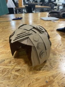
In the beginning, everyone was on board with making a helmet. Our original idea was for this helmet to be worn by everyone, but we thought it would take too much time to make 5 helmets. If all 5 helmets were made we thought that it would be cool whenever the helmet detects negative energy it will absorb that and transfer it to big storage in the middle of the city. The machine will sort out the negative energy into a brainwave and write it on a big monitor seen by all. As this process repeats throughout the whole day, it will present many brainwaves at the end of the day. In a way, it is making a form of art with the users involved. I  was thinking at the beginning about how this will fit with my definition of interactiveness and that was what I came up with. It does not have a set pattern and everyone’s brainwaves are different. When there are no set variables and it is all up to the user to make the artwork, I regard that as interactive. Our group thought that if there is a set variable every time the user does it, it will not be considered interactive. But sadly we were not able to make it such grand. So instead we made one helmet. It will be worn by the child to remove the sadness that he has absorbed from the whole city. We also thought that it would be cool to have it be connected in some way to modern times. So we decided to make one helmet and add extra parts to it to make it look more futuristic. 

Make:

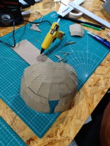
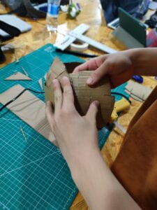
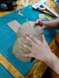
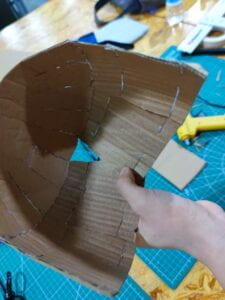
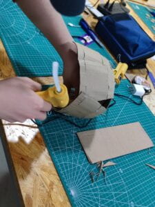
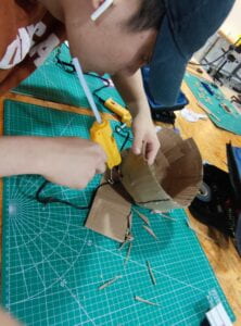
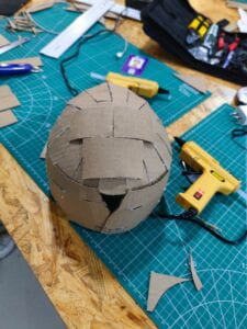
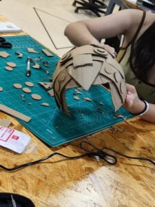
We began by choosing a groupmate head we want it to fit on. Also since cardboard is so flexible, it was also easy for it to fit on some of our groupmates’ heads who are bigger. We first cut two half circles out from cardboard. We then cut slits around the half circles, in order for it to curve inwards when we hot glue it. We also cut out rectangles for the side of the helmet. Using the same process, we cut slits and folded them in. After completing that we have the back of the head part of the helmet complete. We then attached the other circle to the front, to create the top and front of the helmet. We also added more rectangles parts to the front to create the side of the helmet. As this was only the base of the helmet, there were many not-pretty parts. There were a lot of hot glues present throughout which made the aesthetic of it look ugly. To cover this up, We started using cardboard of different sizes to make the design and also cover up a lot of flaws on the helmet. We called this part the decoration part. Also, the part that makes the helmet look more futuristic, is where many of the functions and buttons got put in. To make it not look so flat, we layered the cardboard on top of the cardboard. For example, we stacked a big circle on the button and then layered it with two more circles of smaller sizes to make it look more full. We did try at the end of the making process to add an eye shield for the helmet, but we found that the helmet was too short of the sides to have it put on. We did try to make it but it also became hard to move it up and do when the hot glue was put on it. So we just scratched it out of our idea. We thought that overall our final design and the helmet came out decently. We thought it would’ve been cooler if we had added colors onto it, compared to other groups. 


Reflection:

I felt that everyone made it clear what the strengths are at the beginning of the project. We made sure that everyone made a contribution to the project as a whole. We had two groups, one group was focused on making the groundwork of the helmet and the other group was focused on making the outer decorations of the helmet. We also combined everyone’s thoughts to come up with the design at the end. I was part of the group putting down the groundwork of the helmet. I also gave some of my thoughts on the design of the helmet as I came up with the idea of layering the helmet and making it more sophisticated. I also helped out cutting pieces for the design of the helmet, which I really enjoyed. For the performance, I had a clear idea of what we are going to do. I made sure to make everyone’s strong suits shine. I also directed the rehearsal and made sure everyone had a clear idea of what they are going to be doing. In the end, I felt everyone came together really well and the performance was performed decently, with only a few minor flaws. 


Performance:

We began this performance in the Utopia of Omelas. We wanted to explain the background of the story a little and how our machine was used in the story. We used the helmet to help the child remove all the sadness in him so that he can be happy like everyone else. Then we transformed the time period to the modern time. We had two people form a door, it is like a detection door students see when they enter NYUSH. The door itself detects negative energy and when it is detected, the guards will be notified. They will then send the individual to a one-on-one meeting session. In that session, the doctor will have his assistant put the helmet on the patient. We had another group member behind the patient to act as the monitor. As a way of absorbing the negative energy and writing out the brainwaves. The triangles behind the helmet are the Bluetooth that sends the data to the monitor. We also have another individual act as the technician. We then will upload these data to “Sicko Mode” the big brain that keeps all these data and stores them for future use. We thought that it was gonna be cool to have an audience come up and try it. So we called an audience to come up and try our machine. Overall I give our performance an 8/10. I do wish that the doctor would’ve sat on the side of the patient, rather than in front of the audience. That way the audience will also be able to see the expression of the doctor. So that was one of the flaws of our performance. 

Assessment:

I felt that Lesley’s group was the most interesting and engaging compared to the rest. The idea of a VR and taking a further was really interesting. They also gave it the ability to touch and smell its surroundings. So I felt that their overall performance and idea were the best out of the rest of ours. It was also really cool how one of the members acted as the sea sound and like a thought bubble. The overall design of the project was also very unique and interesting. I was surprised that they were able to make a pair of gloves. Also, the color they used for their piece was also eye-catching. Their stories were also the same as ours. I felt that although the kid might be able to remove his sadness for a bit and make him forget about it. It will still come back. But it could also get rid of the negative energy forever. Because if I remembered correctly, it will just make them forget about the stuff they are going through by transporting their minds into a real-life place to relax. I feel that their project perfectly fits the criteria for this project. It was really interactive for the user and they were able to do anything they want in this virtual world. Without them explaining the use of the artifact, just watching the performance gave me a clear image of what its purpose was. Overall I would give their performance a 9.5/10 because it was a truly wonderful performance. My only suggestion would’ve probably been adding parts for the leg and feet. So when they are walking on the beach their feet will also feel the sand. Making the whole artifact a full body interaction. 


Recitation 3: Workout

Step 1: Prepare your tilt sensor

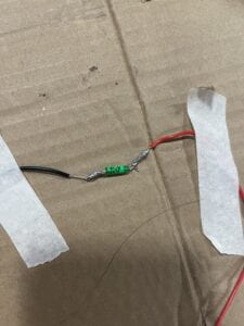
I grabbed two wires and stripped both ends of them. I then took the tilt switch and intertwined it together with the exposed wire. I then heated up my soldering iron and soldering metal and soldered them together. 

Task #2: Connect

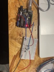
I connected a blue wire to GND and red wire to 5V on the Arduino Uno. I also connected another blue wire to D2 on the Arduino Uno. I placed a resistor onto the breadboard and connected the 5V wire on one side and D2 wire to the other side of the resistor. I also connected the GND wire to the negative power source of the breadboard. Then I took the black wire on my tilt switch and connected that to the negative power of the breadboard. I then took the red wire of my tilt switch and connected it on the same row of the D2 wire. Lastly, I connected the negative end of the capacitor to the negative power source and the positive end on the same row as the D2 wire and the red wire of the tilt sensor. 

Task #3: Program

CODE:

int SENSOR_PIN = 2;
int tiltVal;

void setup() {
pinMode(SENSOR_PIN, INPUT); // Set sensor pin as an INP
Serial.begin(9600);
}

void loop() {
// read the state of the sensor
tiltVal = digitalRead(SENSOR_PIN);
Serial.println(tiltVal);
delay(10);
}

Step 2: Refine the code 

CODE:

int SENSOR_PIN = 2;
int tiltVal;
int prevTiltVal;

void setup() {
pinMode(SENSOR_PIN, INPUT); // Set sensor pin as an INPUT pin
Serial.begin(9600);
}

void loop() {
// read the state of the sensor
tiltVal = digitalRead(SENSOR_PIN);
// if the tilt sensor value changed, print the new value
if (tiltVal != prevTiltVal) {
Serial.println(tiltVal);
prevTiltVal = tiltVal;
}
delay(10);
}

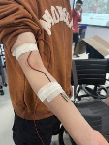
Step 3: Wear your sensor

Step 4: Bicep Curl Workout!

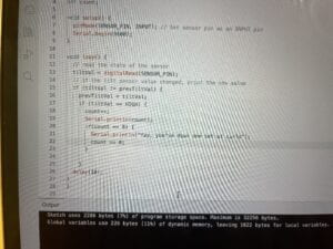
CODE:

int SENSOR_PIN = 2;
int tiltVal;
int prevTiltVal;
int count;

void setup() {
pinMode(SENSOR_PIN, INPUT); // Set sensor pin as an INPUT pin
Serial.begin(9600);
}

void loop() {
// read the state of the sensor
tiltVal = digitalRead(SENSOR_PIN);
// if the tilt sensor value changed, print the new value
if (tiltVal != prevTiltVal) {
prevTiltVal = tiltVal;
if (tiltVal == HIGH) {
count++;
Serial.println(count);
if(count == 8) {
Serial.println(“Yay, you’ve down one set of curls”);
count = 0;
}

}
delay(10);
}
}

Step 5: Exercise Challenge

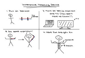
Since my group was not able to get to this step, I’m here to explain a little bit about what we would’ve done. Our group was thinking about doing jumping jacks. When the arm goes down it will be LOW and when it goes up it will be HIGH. In this case when it goes from LOW to HIGH it will count as 1. We were also thinking about adding a line of code in which when the individual has done 8 jumping jacks it will peep or play a short music. 

Reflection:

The tilt sensor has a small ball within it that tracks HIGH and LOW. So when the ball moves from one side to the other it will count 1 if the code is written to count that. So if the tilt sensor is not placed in the right angle it might miscount or not count in some cases. We had to adjust our tilt sensor a few times for the code to work accurately. We did try shaking it and the sensor kinda went wild, but due to the line of code that says delay it will slow the down the amount of time it is registered into the system. We also noticed an error when we were programming. I tried to reset the count back to zero and coded (count == 0), but this in fact was a coding error. I later changed the code to (count = 0) and it worked. So we figured out that one equal sign and two equal sign has fundamentally different meanings to them. 


Interactive Training Device:


Recitation 2: Arduino Basics

Circuit 1: Fade

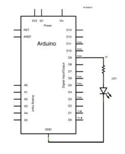
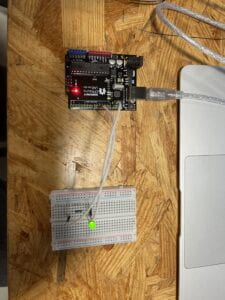
To power up the Arduino UNO, I first connected the USB to my computer. The purpose of this circuit is for the light of the LED to fade from high to low. I first connected a wire from D9 to a resister. Then I connected the positive end of the LED light to the other end of the resister. To conclude the circuit, I connected a wire from GND on the Arduino UNO to the negative end of the LED light. By uploading the code on Arduino IDE to Arduino UNO, we complete this circuit. 


CODE:

void setup() {
// put your setup code here, to run once:
pinMode(9,OUTPUT);
pinMode(8,OUTPUT);
}

void loop() {
// put your main code here, to run repeatedly:
digitalWrite(9, HIGH);
delay(100);
digitalWrite(9, LOW);
delay(100);
// put your main code here, to run repeatedly:
digitalWrite(8, HIGH);
delay(1000);
digitalWrite(8, LOW);
delay(1000);
}

Circuit 2: toneMelody

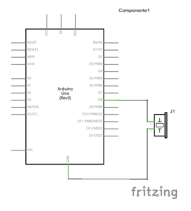
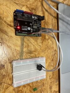
For this circuit, we had to have the buzzer play a pre-coded melody. First, I connected a wire from D8 on the Arduino UNO to the negative end of the buzzer. Then I connected a wire from GND on the Arduino UNO to the positive end of the buzzer. To complete this circuit, I uploaded the Arduino IDE code to the Arduino UNO. 


CODE:

“#include “pitches.h”

// notes in the melody:
int melody[] = {
NOTE_C4, NOTE_G3, NOTE_G3, NOTE_A3, NOTE_G3, 0, NOTE_B3, NOTE_C4
};

// note durations: 4 = quarter note, 8 = eighth note, etc.:
int noteDurations[] = {
4, 8, 8, 4, 4, 4, 4, 4
};

void setup() {
// iterate over the notes of the melody:
for (int thisNote = 0; thisNote < 8; thisNote++) {

// to calculate the note duration, take one second divided by the note type.
//e.g. quarter note = 1000 / 4, eighth note = 1000/8, etc.
int noteDuration = 1000 / noteDurations[thisNote];
tone(8, melody[thisNote], noteDuration);

// to distinguish the notes, set a minimum time between them.
// the note’s duration + 30% seems to work well:
int pauseBetweenNotes = noteDuration * 1.30;
delay(pauseBetweenNotes);
// stop the tone playing:
noTone(8);
}
}

void loop() {
// no need to repeat the melody.
}

Circuit 3: Speed Game

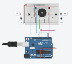
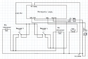
For circuit 3, we are tasked to build a simple game. To begin this circuit I started with wiring the Arduino UNO. First, I connected a USB from my computer to the Arduino UNO to establish a power source. Then I started by connecting all necessary wires to the Arduino UNO. I connected a wire to D2, D3, D8, D10, D11, GND, and 5V. I started building the circuit from left to right. I first connected the GND to the negative socket and 5V to the positive socket on the breadboard. Starting from the left side, I connected a back wire from one end of the negative socket to the other end of the negative socket on the breadboard. I also connected both of the positive ends together with a red wire. I set a button on the left end of the breadboard and connected a red wire from the positive power source to the button. Then, I connected the blue wire connected to D10 to the other side of the button. There I set a 10K resistor in between the button and the blue wire. Then I connected a black wire to the other end of the resistor to the negative power source on the top of the breadboard. Then, I placed a LED to the right of the resistor I placed down already. There I connected a resister vertically across the two sections of the breadboard while connecting it with the negative end of the LED light. Lastly, to complete the left side, I connected a black wire to the end of the resistor to the negative power source on the bottom. There I connected the blue wire on D2 on the Arduino UNO to the positive end of the LED light. 

Continuing with the middle. I set a buzzer in the middle of the breadboard. I connected a green wire on D8 of the Arduino to the positive end of the buzzer and I used a black wire to connect the negative end of the buzzer to the negative power source on the bottom of the breadboard. For the right side, I repeated the same process as I did for the left side. After uploading the pre-coded code from Arduino IDE to Adruino UNO, we completed the little game. 

I did run into a problem when I tried to upload the code into the Arduino UNO. As it failed to upload because I did not correctly select the board I needed to upload to. To fix this all I had to correct was to choose to connect the Arduino IDE to Arduino UNO. Problem solved. 


CODE:

int buzzerPin = 8;
int button1 = 11;
int button2 = 10;
int led1 = 3;
int led2 = 2;

int goal = 10;
int buttonState1 = LOW;
int previousState1 = LOW;
int buttonState2 = LOW;
int previousState2 = LOW;

int counter1 = 0;
int counter2 = 0;
boolean winner1 = false;
boolean winner2 = false;

// the follow variables are long’s because the time, measured in miliseconds,
// will quickly become a bigger number than can be stored in an int.
long time = 0; // the last time the output pin was toggled
long debounce = 200; // the debounce time, increase if the output flickers

void setup() {
// put your setup code here, to run once:
Serial.begin(9600);
pinMode(buzzerPin, OUTPUT);
pinMode(button1, INPUT);
pinMode(button2, INPUT);
pinMode(led1, OUTPUT);
pinMode(led2, OUTPUT);
Serial.println(“******************* RACE THE LED *******************”);
delay(1000);
Serial.println(“READY”);
delay(1000);
Serial.println(“SET”);
delay(1500);
Serial.println(“GO!!!!!!!!!!!!!!!!”);

}

void loop() {
// put your main code here, to run repeatedly:
buttonState1 = digitalRead(button1);
buttonState2 = digitalRead(button2);
//Serial.println(buttonState1);

//this checks the times player 01 has pressed the button
if (counter1 < goal && winner2 == false) { if (buttonState1 != previousState1 && millis() – time > debounce) {
if (buttonState1 == HIGH) {
counter1++;
Serial.print(“player 01: “);
Serial.println(counter1);
time = millis();
}
}
previousState1 = buttonState1;
if (counter1 == goal && winner2 == false) {
winner1 = true;
digitalWrite(led1, HIGH);
Serial.println(“PLAYER 01 WINS”);
playMelody();
}
}

//this checks the times player 02 has pressed the button

if (counter2 < goal && winner1 == false) { if (buttonState2 != previousState2 && millis() – time > debounce) {
if (buttonState2 == HIGH) {
counter2++;
Serial.print(“player 02: “);
Serial.println(counter2);
time = millis();
}
}
previousState2 = buttonState2;
if (counter2 == goal && winner2 == false) {
winner2 = true;
digitalWrite(led2, HIGH);
Serial.println(“PLAYER 02 WINS”);
playMelody();
}
}

}

void playFreq(double freqHz, int durationMs) {
//Calculate the period in microseconds
int periodMicro = int((1 / freqHz) * 1000000);
int halfPeriod = periodMicro / 2;

//store start time
long startTime = millis();

//(millis() – startTime) is elapsed play time
while ((millis() – startTime) < durationMs) {
digitalWrite(buzzerPin, HIGH);
delayMicroseconds(halfPeriod);
digitalWrite(buzzerPin, LOW);
delayMicroseconds(halfPeriod);
}
}

void playMelody() {

playFreq(262, 100);
playFreq(294, 100);
playFreq(349, 100);
playFreq(294, 100);
playFreq(440, 200);
delay(100);
playFreq(440, 400);
playFreq(392, 400);
delay(300);
playFreq(262, 100);
playFreq(294, 100);
playFreq(349, 100);
playFreq(294, 100);
playFreq(392, 200);
delay(100);
playFreq(392, 400);
playFreq(349, 400);

}

Documentation Questions 

Question 1: Propose another kind of creative button you could use in Circuit 3 to make the game more interactive. Read and use some material from the Physical Computing, Introduction Chapter (p. xvii – p. xxix) to explain why this button would make this game more interactive.

Answer 1: Another button that could be used could be our DIY pad we made in our first recitation class. Instead of pressing it fast enough, it could automatically generate a word, and whoever spells the word out first with morse code wins. This way there is a higher level of conversation between the physical world and the virtual world of the computer also known as transduction. The computer would have to recognize the word that the user is spelling and also have to compare it with the word it generated. It would make the game more interesting as it requires the user and the computer to recognize morse code. Instead of thoughtlessly pressing the button, the user has to actually think and carefully press it. 

Question 2: Why did we use a 10 kOhm resistor with each push button? (Psssst… Go back to your slides for this answer)

Answer 2:When the button is not pressed, the resistor serves as a connection to the Ground. A pull-down resistor of 10 kOhm ensures we always read LOW when the button is not pressed

Question 3: In the book Getting Started with Arduino there is a clear description about the “Arduino Way” in chapter 2. Find a project that you find interesting that can be used as an example for these kind of projects. Cite it in adequate manner, include a picture, and explain the reasons that you chose it.

Answer 3: In people’s eyes trash or broken machines that are thrown away are just broken junk. To people who enjoy building or are curious, this is a cheap and easy outlet to learn. These machines or toys have gone through many experts’ hands before reaching the market. An example of this will be clocks. Simples clocks already have multiple components put together to make them work. Often or not the materials needed for a clock can be found in all sorts of machines and toys. When technology and higher-end programming are put into clocks it gets even more complex. Clocks are always around us and often times they only last for a time period before they get thrown away. They are an excellent source of materials for people to tinker with. With programming, it is even possible to add LED lights onto them and make them light up every set time period. The inside of clocks can be both a hard and easy thing to learn. As you learn more about clocks and their inner workings of them, when approaching higher levels of machines it will become easier to understand them. Furthermore, clocks come in all different sizes. The alarm next to our bed, the clock on the wall, the clock on your wrist. They all have intricate designs in them and are there for us to learn when taken apart. 

Looking inside Clocks, http://www.bowerswatchandclockrepair.com/lookinginsideaclock.htm.

Research Project: Read

READ

Title: Imaginative Gear 

In “Veldt”, audiences are presented with this changing room that changes with the user’s imagination. My idea for this story is what I call the Imaginative Gear, which similar to the changing room, has the ability to change your clothes that is the best fit for the environment. It also has the capability to sense danger based on the user’s reactions and form a protective barrier to protect them from harm. It also has the ability to change based on your mood and emotion, or even your imaginative system. You can literally create a new type of clothing with simply an idea in your head. There are currently no such inventions currently present in real life. There is clothing that does change but those are all very limited to only a few types of changes. This type of invention first has to solve the issue of the mass amount of materials needed to deal with all kinds of environments. Since different scenarios and environments need specific gear to protect them from harm. Only when a universal material is found, can this project truly can be complete. 

Title: Remover

In “The Ones Who Walks Away From Omelas”, the story is set during a summer festival in a utopian city known as Omelas. The prosperity of Omelas depends on the perpetual misery of a single child. My idea for this story is called the remover. While instead of everyone’s happiness relying a single on the misery of a single child, why not create a gear that absorbs the negative emotions and misery of a person? A sensor will be built throughout the city, when it detects sadness or misery, it would send electrical waves to remove such emotions. Every person’s emotion creates different wavelengths, and while the machine absorbs wavelengths it will present them on a big wall. At the end of the day, an artwork is presented in the middle of the city showing all the wavelengths together. It is a way of making sad emotions into a form of art that heals the individuals who look at it, as they could be part of the making of such art. To collect such wavelengths, there are already machines available to collect such data. There has been no current invention that could remove negative emotions from an individual. Some issue that this type of interactive artifact can have is how it will affect the brain negatively. 

Title: Immersion

In “The Plague”, people are becoming statues, yet in another sense, their brain is still active and considered alive. My idea is to create a digital platform, where an individual’s brain is uploaded onto the digital platform and continues living there. Instead of being trapped in their stone body and having the risk of being killed or thrown out, this will in sense let them keep living but in data form. A technology that connects to this invention is VR gear. It brings the user into the game or environment of their choice. Although your brain is not completely in the system, it achieves the idea more or less. As uploading a person’s consciousness into a digital world is riskier and requires a lot more programming compared to VR gear. In this digital world, people can interact with everything that is part of the system. They can live how they desire and perform actions of their choice. It is merely a platform for those that have been affected by the disease to have a second chance at life. An issue with this invention is maintenance. If in theory everyone on earth gets affected by the disease there would be no one able to update and keep the world in check. 

Research Project: Research

RESEARCH

Interaction: A collaboration between artist and audience. It is an instrument or environment that the audience takes part in, with minimal interference from the artist. It is an outlet or interaction between the artist and the audience. It is a performance between artist and audience, that allows the audience to create artwork the way they desire. Interaction should be unpredictable rather than a set code that does events on repeat. 

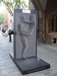
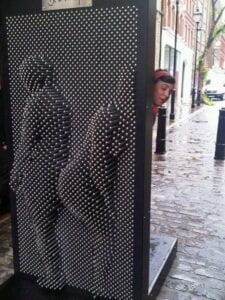
Interactive Art Project: A great example of an interactive art project is pin arts. It is an instrument that the audience can physically take part in. It requires little to no interference from the artist or user that created it. Pin arts can either be big or small. The size and concentration of the pin board all depend on the artist and observer. Through the pinboard, the audience can design and create any image they desire. There is no set or correct image that should be created, it is all based on how the audience interacts with the instrument. This is why pin arts are unpredictable as no two pin boards could in theory be the same. As different users would create different artworks that are outside the initial idea in the creator’s head. Pin arts triggered my idea of interaction because the first time I had interactions with it, there were no instructions handed to me. It was almost similar to an invisible force making my hands or face push the pins on the board. It required me to have no interaction with the artist besides the instrument he/she created. What should be used is available to us users, and what should not be used is not included or blocked off. Pin art is a fun way to relax and make realistic art at the same time. When the first user makes art from it and leave, the second user will come around and make a new one. This cycle repeats endlessly. When pin art is magnified and put in public, it sprouts interactivity with people on the street. Since the pinboards have two sides, there could be a person standing on both sides and pressing at them at the same time. 


https://no.pinterest.com/pin/450782243938274568/?mt=login  

https://no.pinterest.com/pin/450782243938288781/?mt=login&nic_v3=1a1gJfLcJ

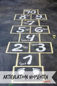
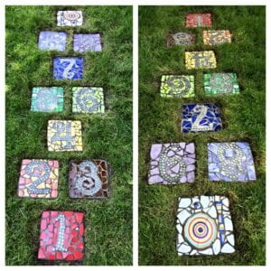
Non-interactive art project: A idea of non-interactive art project would be hopscotch. Hopscotch does not fit into the definition of interaction because every sequence done by the user follows a set code that is unchangeable. It is a pre-drawn sequence by the artist that the user follows over and over again until it is changed. Hopscotch is similar to the refrigerator light example. No matter how many times you open the refrigerator, the only goal of the light is to open when the refrigerator is opened. Hopscotch follows an order either land with one leg when there is one square or land with two legs when there are two squares. Put squares together and you have a game of hopscotch, which is not really interactive at all as it only follows a set code rather than it being unpredictable. 


https://no.pinterest.com/pin/6473993207091806/?nic_v3=1a1gJfLcJ 

https://no.pinterest.com/pin/62909726029533372/?nic_v3=1a1gJfLcJ

Recitation Documentation 1: Electronics & Soldering

Task 1: Build the circuits 

Step 1:

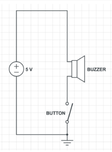
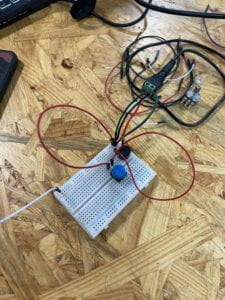
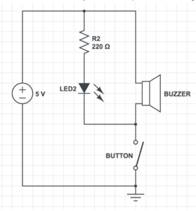
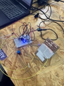
The goal of this circuit is to make the buzzer beep, whenever the button is pressed. First, we connected the power source to the board, with the red wire to the positive and the black wire to the negative. We set the buzzer on the breadboard. We then established a connection from the power to the buzzer. We did this by connecting a green wire to the positive below the red power wire. From there we connected the other end of the green wire to the positive side of the buzzer. We then tried to establish a connection between the power and the buzzer. We set the buzzer on the breadboard. We connected a red wire below the black power wire and connected the other end of the red wire to the negative part of the button. Lastly, we used a red wire to connect the button to the buzzer to complete the circuit. Our circuit did end up working in the end. We had some issues starting off the project. Mainly we did not connect components together with wires, which was what caused it to fail initially. To solve the issue, we used our hands to track where the power went just to make sure everything was linked together. 


Step 2:

Step two was built on top of step one. This step also required the buzzer to beep, whenever the button was pressed. On top of that, a LED light was also required to light up when the button was pressed. First, we established a connection between the resistor and the power source. We set the resistor at the end of the breadboard and connected one side of it with the positive power with a green wire. With that established we connected a LED light to the other end of the resistor. Since the other side of the resistor is connected to the positive side, we set the shorter end of the LED light (negative side) to the resistor. Lastly, we connected the longer end of the LEd light (positive side) to the buzzer with a black wire. With the last touch, we completed this circuit. In this step, we experienced fewer errors compared to step 1. We did, however, moved the buzzer and button around as, because we wanted everything to be spaced out. 


Step 3:

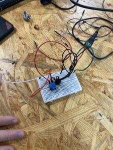
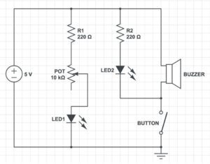
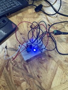
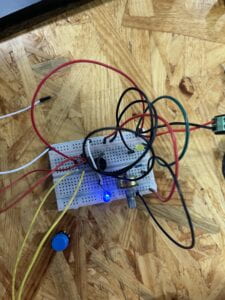
Step 3 is built on the previous two steps. This step required the buzzer and LED to light up, whenever the button is pressed. Furthermore, it also required a LED to be constantly lit, and a potentiometer (POT) which changes the brightness of the LED light with the change in the resistance with the nob. We first set a connection with a resistor to the power source. At first, we used a red wire to connect one side of the power source to the other side of the power source. This way both sides of the positive power source on the ends of the breadboard could be used. From there we connected a black wire to connect one end of the resistor to the positive end of the breadboard. We then connected the other side of the resistor to the right end of the POT. Following that we tried to establish a connection between the LED light and the POT. We connected a black wire to the middle of the POT to the positive end of the LED light. To finish it off we used a white wire to connect the negative end of the LED light to the negative power source. We also had little issues with step 3. We paid extra attention to make sure all the wires are connected to the right power source and the right positive or negative ends. 


Task 2: Build a switch

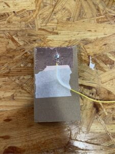
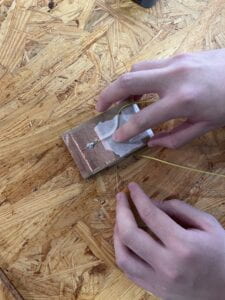
After receiving all our materials we first prepared our wire. We stripped both ends of our wire to expose the wire in it. We then took the copper tape and wrapped it around one end of our cardboard. We then took our stripped wire and bent it so that the exposed wire sits directly on the copper tape. We then took the tape to tape the wire down to the board. Furthermore, while doing these steps we heat up our soldering iron to around 700 degrees. We each took a soldering stick (a metal stick) and test out the soldering iron to see if it is hot enough. We then laid the soldering iron on both the copper tape and wire to heat them up. Then we slowly fed the soldering stick into the soldering iron so it can melt onto the wire and copper tape. What I had the most difficult time with was the soldering part. I did not spread the metal around and it became a lump of metal after only a second of cooling. To fix this I took some more soldering sticks and heat up that and the metal that was original on my board. Which in the end fixed the issue. In the end, it formed a pool around my wire and copper tape, that firmly attached them together. After my partner and I completed both of our switches, we taped them together to form a full switch. 


Task 3: Switch the switches and send a message

This task included all the steps listed in task 1. First, we took out the button that was on the board. Then we took the two wires on our switch and subbed them in for where the button’s original position on the breadboard was. One wire is connected to the negative power source and the other is connected to the positive power source. Lastly, my partner thought of a word to send me in morse code. I was able to guess the word that he sent was MATH. 


Additional Required Questions:

Question 1: What is the function of the resistor R1? (You can read about the reason why LEDs need resistors here

Answer 1: It is necessary to use resistors in LEDs so that they do not get damaged by current flowing through them. Resistors are able to limit the current to below the maximum allowable current that LEDs are capable of handling. Resistors function as a limiter so that LEDs do not exert more currents than is allowed. 

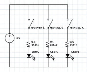
Question 2:  Looking at the following circuit, draw its diagram by yourself.

Answer 2:

Question 3: After reading The Art of Interactive Design, in what way do you think that the circuit you built today includes interactivity? Which degree of interactivity does it possess? Please explain your answer.

Answer 3: The circuit we built today defiantly has a degree of interactivity. As said in the article everything can have interactivity but the degree of interactivity varies. Our circuit includes interactivity because it gives a response whenever we push on the button similar to how the light of a refrigerator has interactivity. I would say that the circuit we build today would have low interactivity. Besides a beep and LED lighting up with every press of the button, there is not much else. The circuit does not offer more than a couple of options similar to the light of the fridge. 

Question 4: How can Interaction Design and Physical Computing be used to create Interactive Art? You can reference Zack Lieberman’s video or any other artists that you know.

Answer 4: The first project that Zack Lieberman talked about was “Drawn”. In this project, after individuals have drawn whatever they desired they have the ability to interact with their artwork, by moving whatever was drawn around. The second project that Zack Liberman talked about was “Iq Font”. It was very interesting how he was able to program a computer to follow the car, and through that make a font that was unique to the car. The last project that was discussed was called “EyeWriter”. It was fascinating how they were able to program this low-cost software and eye tractor for the man with Liguria disease. Through only his eyes, he was able to draw and create artwork. All these interactive arts are made through interaction design and physical computing, which makes it possible that whoever comes in contact with them, is physically able to interact with them and make art. 

Hello world!

Welcome to Web Publishing @ NYU. This is your first post. Edit or delete it, then start creating your site!

Online help is available via the Web Publishing Knowledge Site (wp.nyu.edu/knowledge) and the ServiceLink knowledge base (www.nyu.edu/servicelink). Through ServiceLink, you can find step-by-step instructions, as well as tutorials.

Digital Accessibility

As content creators who create and publish text, images, video, and audio, you must adhere to the NYU Website Accessibility Policy (https://www.nyu.edu/digitalaccessibility/policy) when creating and publishing digital content.

Web Publishing-specific Digital Accessibility Best Practices and examples of how to ensure your content are compliant are available at https://wp.nyu.edu/digitalaccessibility

If you have additional questions, contact the IT Service Desk for assistance. Support is available 24/7/365. For more details, visit www.nyu.edu/it/servicedesk.