Task #1: Make a Processing Etch-A-Sketch:
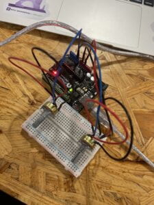
First, I started with the Arduino portion. I used two Potentiometers, one controlling the x-axis and the other for the y-axis. I connected one to A0 and the other one to A1.

I found the Etch-A-Sketch created with Processing and Arduino was super interactive. By controlling two Potentiometers, I can create any drawings or pictures I desire. It was fun just messing around with it and seeing what was made. The interaction required the user to control the two Potentiometers turn them to certain degrees and make a drawing. One would control the x-axis and the other the y-axis. There was not much different from a regular Etch-A-Sketch, it was almost a perfect replica.
Arduino Code:
#include "SerialRecord.h"

// Change this number to send a different number of values
SerialRecord writer(2);

void setup() {
  Serial.begin(9600);

}

void loop() {
  int sensorValue1 = analogRead(A0);
  int sensorValue2 = analogRead(A1);

  writer[0] = sensorValue1;
  writer.send();

  writer[1] = sensorValue2;
  writer.send();

  // This delay slows down the loop, so that it runs less frequently. This can
  // make it easier to debug the sketch, because new values are printed at a
  // slower rate.
  delay(10);
}
Processing Code:
import processing.serial.*;
import osteele.processing.SerialRecord.*;

Serial serialPort;
SerialRecord serialRecord;

float px;
float py;

void setup() {
  background(0);
  size(500, 500);

  String serialPortName = SerialUtils.findArduinoPort();
  serialPort = new Serial(this, serialPortName, 9600);

  // If the Arduino sketch sends a different number of values, modify the number
  // `2` on the next line to match the number of values that it sends.
  serialRecord = new SerialRecord(this, serialPort, 2);

  px = 0;
  py = 0;
}

void draw() {

  serialRecord.read();
  int value1 = serialRecord.values[0];
  int value2 = serialRecord.values[1];

  float x = map(value1, 0, 1024, 0, width);
  float y = map(value2, 0, 1024, 0, height);

  line(x, y, px, py);

  px = x;
  py = y;

  stroke(255);
}
For the Arduino Code, I did not change much from the original SerialMultipleValues sample code I used. Mainly, I took away the millis() code as it was not needed in this task. As the original code only supported one Potentiometer, I replicated the first code for the second Potentiometer.
For the Processing Code, I used the original ReceiveMultipleValues as a basis. I first set up two other float values, px and py, which stand for previous x and previous y. I then set them both to the original value of zero, as they do not have a previous value yet. Lastly, I opted out circle() and used line() instead. Inside the line, x and y represents the point at which it is currently, and px and py, represents the last value the Potentiometer was at.
Task #2:
Teammate: Jason Li
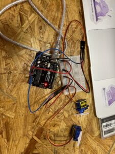
Similar to task 1, we started with the Arduino portion. We used the micro servo in both of our kits. We connected similarly to the Potentiometer, one to A0 and the other one to A1.

Compared to the Etch-A-Sketch, this one was less interactive. The user is not accomplishing anything. They just watch the ball bounce back and forth and the micromotor moves whenever the ball hits the edge of the screen. It would’ve been more interactive if the player was the one controlling the micromotor.
Arduino Code:
#include "SerialRecord.h"

#include <Servo.h>

Servo left;  // create servo object to control a servo
Servo right;

int motor = -1;

// Change this number to the number of values you want to receive
SerialRecord reader(1);

void setup() {
  Serial.begin(9600);
  right.attach(A0);
  left.attach(A1);
}


void loop() {
  if (reader.read()) {
    motor = reader[0];
  }
  if (motor==1) {
    left.write(90);
    delay(500);
    left.write(0);
    motor = -1;
  }
  if (motor==0) {
    right.write(90);
    delay(500);
    right.write(0);
    motor = -1;
  }
}
Processing Code:
import processing.serial.*;
import osteele.processing.SerialRecord.*;

float x;
float y;
float i=0;
boolean left = true;
boolean right = false;
int edge = 0;

// SoundFile sample;
Serial serialPort;
SerialRecord serialRecord;

void setup() {
  // sample = new SoundFile(this, "Ping Pong Table Tennis Sound Effect.mp3");
  // sample.loop();
  fullScreen();

  String serialPortName = SerialUtils.findArduinoPort();
  serialPort = new Serial(this, serialPortName, 9600);
  serialRecord = new SerialRecord(this, serialPort, 1);
  //serialRecord.logToCanvas(false);
}

void draw() {
  //println(frameRate);
  background(0);
  if (i<=0) {
    left = true;
    right = false;
  }
  if (i>=0.95*width && edge==0) {
    serialRecord.values[0] = 1;
    serialRecord.send();            // send it!
    edge = 1;
  }
  if (i<=0.05*width && edge==1) {
    serialRecord.values[0] = 0;
    serialRecord.send();            // send it!
    edge = 0;
  }
  if (i>=width) {
    right = true;
    left = false;
  }
  if (left==true) {
    i = lerp(i, 1.1*width, 0.02);
  }
  if (right==true) {
    i = lerp(i, -0.1*width, 0.02);
  }
  fill(255);
  circle(i, height/2, 70);
}
For the Arduino, I set one motor as right and the other motor as left. Then I created an integer motor and set the value equal to -1. When the SerialRecord Reader equals 1, the motor will also equal one. In this case, the left motor will move to hit the ball. Similarly, when the SerialRecord Readers equals 0, the motor will also equal to zero, causing the right motor to move. This was built off of the Sample code: ReceiveMultipleValues.
For the Processing Code, I implemented the sample SendMultipleValues code as my foundation. I first added the fullScreen () code in place of the size () code. Then I created multiple float, int, and boolean values. For this specific step, I asked the LA’s for help. I was getting frustrated and confused, but after spending time with them it finally worked. The main part that allows this code to work with Arduino is the part when i is between a certain value then the serialRecord value will be either 0 or 1. Which will be right or left for the Arduino. Making either the right or left motor move. We decided to use a lerp code to calculate the number between two numbers at a specific increment. I felt that this part of the recitation was the most challenging for us, as we used functions that we might not have learned in class.