Step 1: Build the circuit
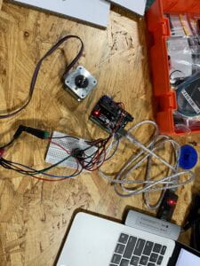
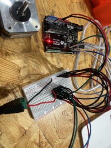
The stepper motor circuit, in my opinion, was quite easy to build. As usual, I plugged my adaptor into my computer along with the cable that connects my computer to the Arduino UNO. The only difference this time was that I used a USB Protector since we are working with higher voltage. As the voltage gets higher, the risk of damaging your computer increases. I first placed the H bridge on my breadboard. I connected a wire from 5V to the positive port and a wire from GND to the negative port of the breadboard. This will allow positive and negative energy to run throughout the breadboard.
Starting with the top left port of the H bridge. I connected the first port to the positive end of the breadboard. Going down, I then connected a wire from D8 to the second port. In the third port, I connected the black wire on my motor to it. Ports 4 and 5, I connected them with a wire to the negative end of the breadboard. Port 6 I connected the green wire on the motor to it. For port 7, I connected it to D9 with a wire. Lastly, for port 8, I connected it to the positive end of the power jack to it.
Starting from the top right of the H bridge. I connected port 16 to the positive end of the breadboard. For port 15, I connected it to D11 of the Arduino. Making our way down, port 14 was connected to the blue wire of the motor. Port 13 and 12, were connected to the negative end of the breadboard. Furthermore, for port 11 I connected it to the red wire of the motor. Port 10 was connected to D10 on the Arduino Uno. Lastly, port 9 was connected to the positive end of the breadboard.
The power jack was also connected to a 12 VDC power supply, as an external power supply. As simply using the computer as a power source, was not enough to show the full capacity of the motor.


Step 2: Build a cardboard mechanism!
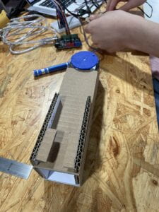
This step was really fun. We first glued the template onto our cardboard. We cut the cardboard according to the lines on the template. After cutting out all parts of the project, we heated up our hot glue gun. We glued everything according to the instructions listed on them. After completing it, we placed the motor on one end of the mechanism and we used a rivet to help the rotating link from staying on the shaft adaptor.

Step 3: Personalize it
For our mechanism, we wanted to tell a story of a person eating ice cream on a hot summer day. We first drew an ice cream cone on cardboard and cut it out. We added some color to it to make it look more appetizing. For our program, we made sure to delay the motor for a good amount of time between each lick the user takes. We did not want the motor to go too fast, when eating ice cream there will be a period between each lick or bite.
Documentation Questions:
Question 1: Choose an art installation mentioned in the reading ART + Science NOW, Stephen Wilson (Kinetics chapter). Post your thoughts about it and make a comparison with the work you did during this recitation. How do you think that the artist selected those specific actuators for his project?
Answer 1: The project that attracted my attention was Daniel Palacios Jimenez’s Waves, 2006. The use of the motor was similar to what we did in recitation, but the speed of the motor would have probably spun faster compared to our motor. That is the case to create the illusion of solid shapes with the rope spinning at a certain speed. Similarly, the motor is used in a way to tell a story but in this case rather than a cardboard telling the story, Jimenez used a rope to tell it. Ropes are all around us. When I was a child I would put something that has weight in between two strings and spin it. When I let go it will make something similar to what he did in this project. He might have got his inspiration from such a small and simple things kids usually do with necklace or strings. The motor is used in this case as a replication of the hand motion or a substitute/start for the system.
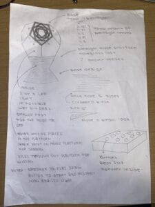
Question 2: What kind of mechanism would you be interested in building for your midterm project? Explain your idea using a sketch (conceptual or technical) with a list of materials that you plan to use. Include details about the ways that you expect the user to embrace in a physical interaction with your project. In particular, explain how would your motor (or motors) with a mechanism will be different than using an animation on a digital screen.
Answer 2: The mechanism that I am interested in building for my midterm is a lampshade and a beat pad. The lampshade will be a geometric pentagon. It will be on a platform, with a motor inside the platform. The motor will also have a platform on top of it in which the LED lights will sit and spin on it. The LED light and motor will be connected buttons. Each button will have a correlating LED light to it. Also, each of the buttons will also have a correlating sound that goes along with it. The buttons and buzzer will be in together to make up the beat pad. There will also be a middle box, where we organize the Arduino and wires. The user will use the beat pad to create any notes or songs they prefer, while doing so they will be able to physically hear the transition between sounds and LED lights. Physically the motor will be mainly spinning one way at a certain speed. The motor’s main purpose in my project is to spin the LED lights. Compared to a screen, it will just tell me it’s going left or right. I will physically be able to see light moving and changing.
