All-Around The Corner
Concept & Design:
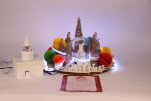
Christmas represents a time of joy, a time with loved ones, and a time to make memories. Concerning Christmas, we titled our project “All-Around The Corner”. This title was inspired by many aspects of Christmas. To begin, Christmas is not complete without Mariah Carey’s “All I Want For Christmas Is You”. It has become a ritual for Christmas. Without it, Christmas cannot be deemed complete. As Christmas is in many senses always around the corner figuratively and literally at this point of the year. As children, we try to stay good throughout the year, to achieve that perfect gift on Christmas day. As they say, Santa is always watching. We wanted to honor that with the word “Around”. The last part of the title was inspired by our project. As we wanted to use the potentiometer as a form of puzzle users have to solve by twisting it. In the end, these inspirations combined to create the title “All-Around The Corner”.
Our project has three main components. The central fabrication piece, a puzzle piece, and a photo booth. Each component is linked together with a Christmas To-Do List. The main focus of our project is to capture the moment of joy they experience from our project. Our project wanted to stay true to the Christmas Holiday. Focusing on making the users joyful and making their experience memorable. Furthermore, we wanted our fabrication to not only be an artwork, but also an interactive piece the users can come in contact with. From the Christmas To-Do List to the presents located throughout our project. We wanted each component to become interactive with the user through any of their five senses. We fabricated miniature presents, to provide the user with the feeling and excitement of opening a present. We made a small puzzle, as such, after they solve it, it will light up all the Christmas lights. It is similar to what many households would do before and during Christmas, but on a smaller scale.
During User Testing, we received many well-developed and excellent feedbacks from the users. Each user had a unique way of interacting with the fabrication. Some opened the snow globe to feel the inside of the project. Others went straight for the presents. Christmas is a holiday that is different for each household. So it was unique hearing certain feedback and details from the users. But all feedback did lead to one issue, that issue being there seemed to be missing an element that helped tied the different aspects of the project together. That led us to eventually make an instruction manual, but more abstract and Christmassy. We show a positive effect from making such a decision. Another issue that happened at the beginning of the User Testing was that Processing took an extensive while to register the numbers sent from Arduino. This issue was quickly fixed with the help of Professor Margaret. Simply adding a delay on Arduino, made our project more smooth flowing. So User Testing was a huge help in pushing our project in the right direction.
Fabrication & Production:
The most eye-catching element of this part was none other than the fabrication itself.
Christmas Tree:
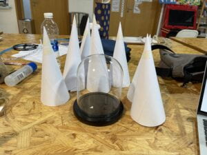
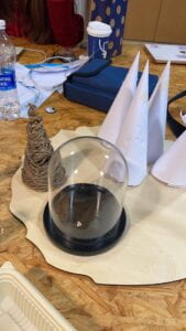
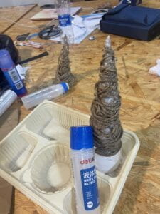
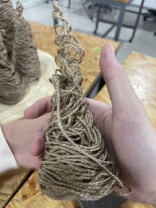
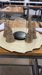
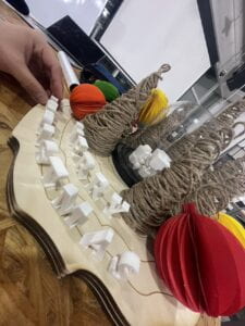
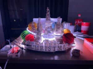
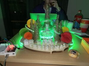
The Christmas trees surrounding the snow globe were fabricated using wood-fibered ropes. These materials were obtained from the fabrication lab. To make such delicate trees, the first step is to take printing paper and make a cone out of it. Use tape to secure the shape, then use scissors to trim the end off. After completing this step it should have a cone that stands on its own. The next step is to wrap the paper cones in plastic wrap. This step is necessary as it prevents the ropes from sticking to the paper and it also makes the removal process easier. Following this step is where it gets messy. We first submerged a ball of rope into the glue and let it sit there for a few seconds. After it is fully coated, we started at the bottom of the cone and worked our way up. For this step to work properly, you must go up and down the cone in an orderly pattern. Furthermore, the bottom of the cone needs to be wrapped more than the top. As if the other way were to be done, it will just collapse. Leave the ropes on the cone for a few minutes to let it solidify. After we used the heater gun in the fabrication lab to quicken the process and help it dry faster. Once we are sure that it is fully dried, we first slowly removed the paper cone and then peeled the plastic wrap from the ropes.
Platform:
For the platform, we decided to laser-cut it. We wanted our platform to be a wood-like texture. To achieve this, we made the sides of the platform rigid. For the top layer of the wood. We also had circular wood-like patterns going from the outer ring of the platform to the middle. In the end, we were satisfied with three layers of wood. We did this step on the computer next to the laser cut. We simply just made a design and stuck with it. As we wanted the edges to look natural rather than planned.

Ornaments:
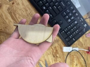
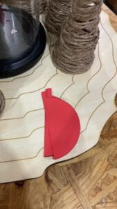
The making of the ornaments was the most time-consuming portion of the fabrication. We first laser cut two half ornament designs. This is to make sure each ornament is identical. We in total made 6 big ornaments and 4 small ornaments. Each ornament had a total of 21 cut-out pieces, making a total of 210 pieces cut-out pieces. We first fold a part of the papers together. Then we placed the laser-cut design at the folded end and trace it. We cut out the traced portion and repeated this process many times. After we accomplished this portion. We first glued the middle part of the individual cut-out pieces together, leaving the sides unglued. When we glued two pieces together we will glue the top and bottom of the ornaments together and leave the middle free of any glue. By doing the above steps we were able to achieve the ornament pattern.
3D-Printing:
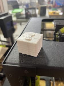
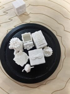
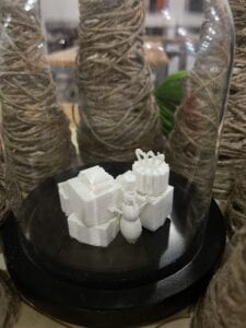
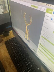
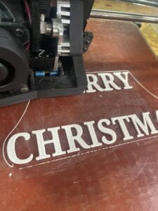
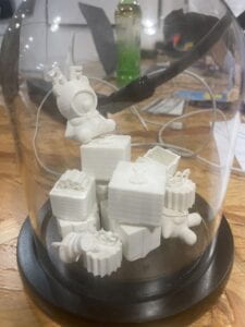
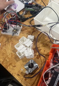
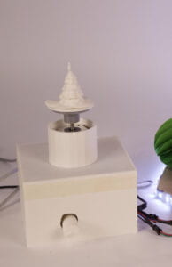
Many 3D-printed objects were found on TinkerCad. For the 3D-printed objects, initially, we wanted to have a deer in front of the snow globe. After a few rounds of testing, we realized that the deer was too small of a scale to be 3D-printed. So we threw that idea out and decided to print out “Merry Christmas”. It turned out better than we had imagined. Furthermore, our main focus for 3D printing was for it to print presents. We wanted to stack these presents on top of each other inside the snow globe. To top it off, we 3D-printed out a bear to sit on top of the presents. Which really helped elevate the snow globe itself. We also printed out small presents that were not sealed on the top. This way the user would be able to open it themselves when they come to our project. The last part we 3D-printed was a little Christmas tree that went on top of the motor. This part in my opinion was a big letdown. Initially, we wanted to have a spinning Christmas tree inside the snow globe, rather than have it sit on the outside. It was a misstep of planning from us. As we believed the project would not seem so fragmented if we did not make such simple mistakes. Lastly, we also printed out a box for our Arduino components. We wanted our project to look sophisticated rather than having wires everywhere.
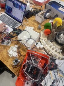
Snow Globe:
Regarding the snow globe, we found it lying somewhere in the fabrication lab and decided to incorporate it into our project.
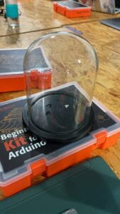
Christmas To-Do List:
The Christmas To-Do List was an addition we made after User Testing. Some of our users had difficulty on which part of the project they should start with. So we created a set of instructions, that were abstract and Christmas themed.

Motor:
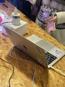
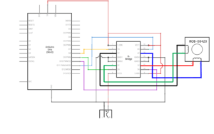
The motor was later added to the project. Initially we wanted to have it be included in the snow globe, but unfortunately it did not make it in there in time. So we decided to add it on top of the box that included all the wires and Arduino parts in it. So it served as a decoration for the Arduino box. But I think in a couple ways it may feel out of place. So this was the part that I missed in my planning. I think in some ways this variable should be eliminated as it does not bring anything more to our project. We used the same wiring as the one we did in Recitation 4.
 \
\
Neo-Pixel Strips:
Christmas is not fully complete with festive lights. So we wanted to include an LED portion on our fabrication. We initially tried to connect all three and use the code to light up all 180 lights. But this did not really work well. As the longer the strips are the dimmer the lights become. So by the point 120th light lit up it was fairly dim. No matter how high I tried to adjust the brightness, it still remained relatively dim. We also tried to use an outside power source but that also did not help the case. So in the end we individually connected each strip to the power source instead of three of them linked together. This helped solved the issue. We also tried many different colors of light, but in the end we decided on a white. It just looked overall more uniform with the rest of the project, compared with the light colors.
Buttons:
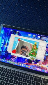
For buttons, we simply used the keyboard in substitution for actual mini buttons. original we wanted to have buttons inside each present, I think it would’ve made the flow of the project better. But unfortunately that did not happen. So we thought to have 3D-Printed letters inside each present that the user could open. The letters they find inside the present will correlate with the specific letter on the keyboard. With the help of the Christmas To-Do List, we thought it was a good substitute. Each letter will correlate with a specific Christmas filter. We had 5 letters representing 5 different filters. The space bar was used as the button to take the pictures. During our presentation, we made the space bar say Christmas, which correlated with what was said on the Christmas To-Do List.
Amplitude:
Since our computer itself has a mechanism that sense the amplitude of sound, we just simply code it so that once the amplitude is at or above a certain value, it will trigger the next step.
Potentiometer:
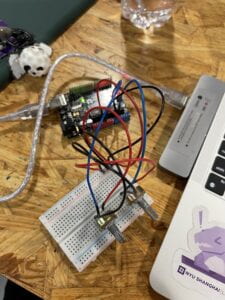
We wanted to have a small puzzle portion in our project. So we decided to use a Potentiometer. It serves as a start and refresh button, but it also acts as a puzzle. Only when the Potentiometer is turned to a certain degree will the Christmas Magic start. When you rewind it back it will just shut everything done. It was a simple part to our project but I thought it was crucial that we had it in there. Since we want our program to run continuously. Ideally we wanted our project to be interacted by more than one audience. As the photo will keep saving itself in our file. So using a Potentiometer and make it act as a start, refresh, and a puzzle to me was a good decision.
Conclusion: Overall, I felt that our fabrication and production of the project turned out very nicely. Everyone in many ways was blown away when they first saw it. Although there were few mistakes here and there, but overall I felt it turned out how we imagined it to be. I felt that me and my partner split the work evenly and we both worked really hard together to achieve the final look of the project.
CONCLUSIONS:
As we mark the conclusion of our time at Century Avenue, we wanted to capture the last bit of joy and memories we may have here. Furthermore, since Christmas is around the corner, we wanted to document everyones joy through our project. I believe throughout the making of this project and through many user testing, we have composed a small album. Flipping through it and looking at everyones smiling face, just makes me remember all the good times we had in this building. Furthermore, each individual was able to keep the photos they took with our project and it was just a very exciting thing.
How the user interacted with our project during the different stages of our project, did align with our initial imagination. It was only after more elements were added did it become a little bit confusing. But this problem was later solved with the Christmas To-Do List.
Our project aligned with our definition of interaction, as it was itself an interactive artwork. Every piece of element on the project was interact-able. Users can interact with each small elements ranging from the presents to the tree, and even the things inside the snow globe. We wanted everything element to be interactive, we for elements such as the Arduino that were not suppose to be interactive. We sealed it tight within a box. The Potentiometer was a mini interactive item as it served more as a start and puzzle for the whole project. Then we have the buttons on the keyboard. Only when they accomplish all the task beforehand will they have the key to the keys on the keyboard. We also have the amplitude, so they have to yell or else it would not start the Christmas magic. Everything was interactive and each small interactive piece builds up on top of each other and produce the final product.
If I had time, I would make the project more uniform instead of looking so scattered. I would one have buttons inside the presents rather than simply letters. Furthermore, I would get a webcam and and projector, this will eliminate the computer and just have a big screen in front of the user. Lastly, I would have the motor inside the snow globe rather than on the outside.
I think that what I learned throughout this project is that there are always more than one answer to a problem. If one does not work try another one. It might not turn out how you wanted it to, but it will still become something close to it. So the most crucial value is to never give up, as there bound to be an answer if you do not give up.
Throughout this class, I have found a love for fabrication and making projects in general. Seeing the project I made for midterm and final, I felt accomplished in that sense. Furthermore, I felt accomplished that I have a basic understanding of Arduino and Processing. I am looking forward to see what else I can make with these two platforms.
Memories are snippets of life that are important to you. People grow and learn through them. Without them you are not who you are today. What better memories are there than joyful ones especially during a festive season. Our project is a tribute and a mechanism that captures the last moments of individuals at Century Avenue. We want it to be memorable and joyous to whoever comes across our project. Time may never rewind, but we will have these pictures that captures what it felt like at that specific moment. Memories should be cherished and held dear to each person. Epically since its the Christmas Season, it is an all important time to make such memories.
Annex:
Materials:
- 3 NEO-PIXEL Strips
- Stepper Motor
- H-bride
- Power Jack
- 12 VDC Power Supply
- USB Protector
- Motor Platform
- Wood
- 3D-Printing
- Glue
- Wood Ropes
- Paper
- Plastic Wrap
- Color Paper
- Wires
- Snow Globe
Arduino Code:
The Arduino code will have a value given from the Potentiometer in the Serial Monitor. Once the value hits 500 or above it will activate the motor and the Neo-Pixel lights, or else it will remain shut. Furthermore, these values are also sent to Processing. So Arduino Code is a simple send values and Processing is receiving values.
#include <FastLED.h>
#include "SerialRecord.h"
#include <Servo.h>
#include <Stepper.h>

#define NUM_LEDS 60
#define DATA_PIN 3
#define CLOCK_PIN 13

const int stepsPerRevolution = 200;

CRGB leds[NUM_LEDS];
Stepper myStepper(stepsPerRevolution, 8, 9, 10, 11);

int c = 0;
// SerialRecord reader(1);
SerialRecord writer(1);

void setup() {
  Serial.begin(9600);
  myStepper.setSpeed(20);
  FastLED.addLeds<NEOPIXEL, DATA_PIN>(leds, NUM_LEDS);  // GRB ordering is assumed
  FastLED.setBrightness(50);
}

void loop() {
  int sensorValue = analogRead(A0);
  writer[0] = sensorValue;
  writer.send();

  if (writer[0] > 500) {
    for (int i = 0; i < NUM_LEDS; i++) {
      leds[i] = CRGB::White;
    }
    FastLED.show();
    myStepper.step(stepsPerRevolution);
  } else {
    for (int i = 0; i < NUM_LEDS; i++) {
      leds[i] = CRGB::Black;
    }
    FastLED.show();
  }
  delay(20);
}
Processing Code:
The Processing code had a few boolean expressions. As I wanted a certain action to be performed when it is true and not activated when it is false. Only when the serial monitor sent from Arduino hits 500 or above will the camera be turned on. Then the user is able to choose a border based on the present the opened. By pressing the space bar it will take a picture of that. Since I set up an array for space bar ahead of time. When keypressed is true it will trigger the next screen which will have a frame with the picture you just took. When that happens the amplitude code will be activated. When the amplitude reaches above . 2 the sound file we had coded ahead of time will be activated. Furthermore, in order to have the pictures taken not override one another, in the “” we added a value so that whenever space bar is pressed it will add 1 to it. This case the program will keep running without having the previous picture overwritten. This code will be shut down once value sent from Arduino is less than 500 and everything resets, and the process starts again.
import processing.video.*;
import processing.sound.*;
import processing.serial.*;
import osteele.processing.SerialRecord.*;

//Value For File:
int x = 1;
int y = 1;
int state = 1;
//Statement Of Completion Of Task:
boolean keyPressed = false;
//Christmas Border Filter:
PImage Border1;
PImage Border2;
PImage Border3;
PImage Border4;
PImage Border5;
//Christmas Frame For Picture Taken:
PImage Page;
//Image Taken From Task 2:
PImage TakenPic;
PImage Introduction;
PImage End;

String[] cameras = Capture.list();

Capture cam;
SoundFile file;
AudioIn microphone;
Amplitude analysis;
Serial serialPort;
SerialRecord sender;
SerialRecord receiver;

void setup() {
  size(960, 720);

  //Camera Setup:
  cam = new Capture(this, "pipeline:avfvideosrc");
  cam.start();

  //Music File Setup:
  file = new SoundFile(this, "AllIWantForChristmasIsYou.mp3");

  //Amplitude Setup:
  microphone = new AudioIn(this, 0);
  microphone.start();
  analysis = new Amplitude(this);
  analysis.input(microphone);

  //Send + Receive Setup:
  String serialPortName = SerialUtils.findArduinoPort();
  serialPort = new Serial(this, serialPortName, 9600);
  //sender = new SerialRecord(this, serialPort, 1);
  receiver = new SerialRecord(this, serialPort, 1);

  Border1 = loadImage("border10.png");
  Border2 = loadImage("border1.png");
  Border3 = loadImage("border8.png");
  Border4 = loadImage("border11.png");
  Border5 = loadImage("border12.png");

  Page = loadImage("Page.png");

  Introduction = loadImage("Introduction.png");

  End = loadImage("End.png");
}

void draw() {

  receiver.read();
  int value = receiver.values[0];
  println(value);

  if (value > 500) {
    //Camera On:
    if (cam.available()) {
      cam.read();
      //Center Camera:
      imageMode(CENTER);
      image(cam, width/2, height/2, width, height);
      if (keyPressed == false) {

        //Buttons For Filter Change:
        if (key == 'n') {
          Border1.resize(960, 720);
          imageMode(CENTER);
          image(Border1, width/2, height/2);
        } else if (key == 'y') {
          Border2.resize(960, 720);
          imageMode(CENTER);
          image(Border2, width/2, height/2);
        } else if (key == 'u') {
          Border3.resize(960, 720);
          imageMode(CENTER);
          image(Border3, width/2, height/2);
        } else if (key == 's') {
          Border4.resize(960, 720);
          imageMode(CENTER);
          image(Border4, width/2, height/2);
        } else if (key == 'h') {
          Border5.resize(960, 720);
          imageMode(CENTER);
          image(Border5, width/2, height/2);
        }
      }

      if (keyPressed == true) {

        //Picture Frame For Picture Taken:
        Page.resize(960, 720);
        imageMode(CENTER);
        image(Page, width/2, height/2);

        delay(500);

        TakenPic.resize(384, 288);
        imageMode(CENTER);
        image(TakenPic, 300, 255);

        state = 2;
        if (state == 2) {
          ////Amplitude Analysis;
          float volume = analysis.analyze();
          if (volume > .2) {
            file.stop();
            file.play();
            state = state + 1;
            delay(500);
            keyPressed = false;
          }
          if (state >= 3) {
            state = state - 2;
            file.stop();
            file.play();
          }
        }
      }
    }
  } else {
    End.resize(960, 720);
    imageMode(CENTER);
    image(End, width/2, height/2);
    file.stop();
  }
}


void keyPressed() {
  if (key == ' ') {
    keyPressed = true;
    saveFrame("data/MerryChristmas" + x + ".jpg");
    x = x + 1;
    TakenPic = loadImage("MerryChristmas" + y + ".jpg");
    y = y + 1;
  }
}
Final Video:
Final Picture:
