Recitation 9: Digital Fabrication

Step 1.1: Stand design

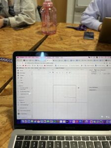
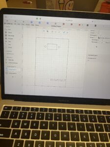
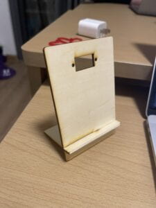
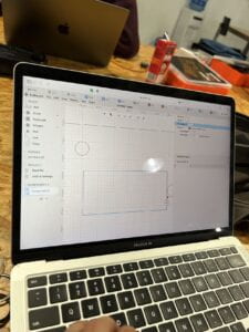
To begin this fabrication, we started by making the stand. I first had “Grid snapping” on. I dragged a corner of a rectangle to the origin. The measurements was 80mm wide and 120mm tall. Furthermore, I changed the unit to mm. My partners rectangle was 80mm wide and 60mm tall. We both added a round corner modifier with a 3mm radius rounded corner. Then we added another rectangle with the size of 40mm wide and 2.8mm tall. We placed it it on the right side edge of the rectangle with -17.5 on the y axis. To incorporate the two rectangles we performed a “Boolean Difference”, allowing us to subtract one shape from the other. 

For the next step we had to measure out the servo motor. The servo motor was 32mm wide and 13mm tall. So we added another rectangle with that measurement. The circles on the side of the servo motor was 4mm in diameter. So we added two circles with a diameter of 4mm. The circles had around 2mm distance from the base of the servo motor. Lastly, we selected all the lines of our design, right-clicked and selected Group (⌘G / Ctrl+G).


Step 1.2: Pattern design

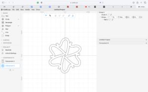
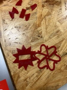
For my design, I drew an interesting line with the pen tool. After I was satisfied with the line that I drew, I clicked Modify-Rotational Repeat. From there, I clicked Modify-Outline Stroke. I made the strokes thicker from the standard value. Then I rotated the whole shape until I liked the design of it. Then I inputted a small circle with a 4.5mm radius in the center of the shape. This is needed so that the servo motor will fit in there. My partner added a rectangle to the middle of her shape with a measurement of 32mm wide and 13mm tall for the base of the servo motor. 

Step 1.3: Export your design

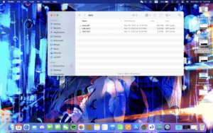
We then explored our file to the already prepared Google Drive for laser cutting. We clicked File -Export SVG. Then we headed to room 823 for the actual laser cutting. 

Step 2: Laser cut

Step 3: Assemble 

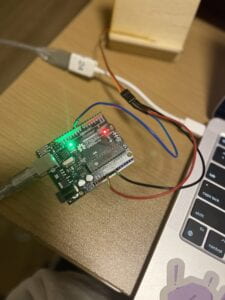
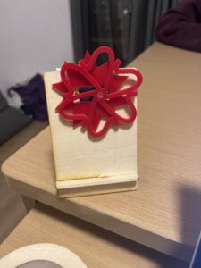
After assembling everything, we connected the servo motor to Arduino. With a wire going to 5V, one to GND, and one to D9. For Arduino, I used the example found in File > examples > Servo > Sweep. 


      •  


Final Project: Proposal Essay

BRAILLE PIANETTE

Music serves the purpose of expressing and modulating emotion. For visually impaired people, the piano serves as a musical instrument, which transmits their inner feelings to the womessage Our goal is to bring light and music to their dark world. 

A key step to learning to play the piano is to know where all the notes are. For the visually impaired, this becomes more challenging, especially the piano, which is a tactical instrument. We hope that every note contains Braille so that when they feel the piano, they can tell exactly which note is where. Every piano will be customized according to the wishes of each pianist. Some people might want a forest theme. So the background of the piano will be flowers and plants. So that they can feel the forest. In addition, these parts can be taken off and replaced. We hope to cut out the piano with laser cutting. Then, we will continue to concentrate on its production. From there, we will work on the Arduino and connect it. Finally, we would program Processing. For Processing, we want to display the notes on the screen when notes are pressed. . It is similar to piano tiles, but the direction is opposite. In the whole process, we hope to make a mini version to test it.

Walking around NYUSH, Braille can be seen everywhere around the school. Walking into the elevator, I feel Braille on the buttons. When walking into a classroom, I see braille on the sign. Yet, when I feel the piano, I do not feel any braildo not knowme start thinking, how can a visually impaired person learn piano? Therefore, my idea originated from my interest in using Braille on piano. Braille and piano already exist, so I hope to create a tool that can help visually impaired people who have no knowledge of piano learn piano. In addition, people with visual impairment depend heavily on their hands to feel the world. So I hope that every piano can be customized so that when they play the piano, they can also feel a part of their imagination. Finally, it’s also compensation for my mid-term project. As for the mid-term project, the sound released is not the cleanest and most elegant. Generally speaking, I feel that this project will definitely change how visually impaired people learn piano.

All – Around The Corner

Joy is universal, and so is Christmas Season. Over decades of interaction between cultures, Christmas has gradually evolved into a universal holiday. All-Around The Corner is an interactive artwork, that captures a glimpse of joy where Christmas has arrived. 

Our project aims to capture the joy and laughter of users. Walking around Shanghai, individuals become exposed to magnificent decorations. Streets filled with the Christmas Spirit. We want to condense something grand into a piece of interactive artwork that users can take part in. For the centerpiece, we wish to have a snow globe. For the platform, we are thinking about a wood-styled circular platform. Around the snow globe, there are gonna be Christmas trees and ornaments. The front has big letters that print “Merry Christmas”. For processing, we would like to have some sort of photo booth. As the user completes certain steps they will come to the photo booth to take a picture to document their completion of the task. Our first main focus would be the fabrication of the project, as there are a lot of areas that need to be 3D printed and laser cut. We would focus more on the processing part after the completion of fabrication. We would like to be completed or have all foundations completed before the user testing. 

Christmas represents a year of joy and wonders. We wanted to create an interactive artwork that inspires the user to get into the Christmas spirit. Our inspiration mainly came from the Christmas Season. As a lot of students this year are not able to experience Christmas together with their friends, we wanted to take this opportunity to help them document that joy. The interactive portion of the project would be the task that leads up to the photo booth. The task they must complete is like Santa’s little elves. At the end of the day, we want this to be a Christmas experience for our users. We only go through things once in our life, but memory is what documents those little bits and pieces in our everyday life. Even after the completion of this project, it can just become a decorations user can have in their home. Possibly with a printed-out photograph that captured that very second of joy they experienced. 

Final Project: Three Project Proposals

Proposal 1: Truth or Dare Jenga

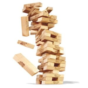
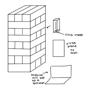
For this idea, Jenga is a popular game that has been with us for many generations. It is a form of game that is easy to play and requires some level of technique in there. For my idea, I thought about on top of the original game, I want to add another layer of fun to it. I want it to be more than just pulling a brick and placing it on top and repeating the process. I want to spice it up a little. So I thought about why not add an element of truth or dare to the original game. When the user pulls out a specific brick, they can scan it with their phone. The phone will generate a number for them. When they input that number into Arduino, a certain card will pop up. When the user clicks the card either a truth or a dare will pop out for them to do. I want to make this game more fun and interesting to play. Because although it may be thrilling to pull bricks and stack them, it would also be more interesting if for each brick they pull out a certain truth or dare question will pop up for them. I am just trying to add more fun to the already fun game. The project I hope to redefine Jenga for the old generation and update it so it doesn’t fall into the history of games. In this project, a lot of people have had contact with this, so I want to relive their first time playing this game. 


Proposal 2: Protective Cube

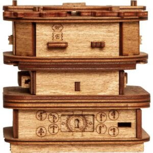
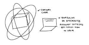
Online security has always been an issue in the following era. Trying to keep your data online safe may be a tough task. So I wanted to cybersecurity tangible. So I thought about making an escape cube. So whenever you try to log into something very personal or top secret you would have to fully solve the cube. Each step after you solve it will have a corresponding question that pops up on the screen requiring you to answer. If you answered correctly, it will pop up a clue on how to solve the step of the cube. For people who just love to play with locks and cubes, this might be enjoyable for them. On the other hand, this device can act as protection for online users. As hackers now can not just hack the online portion they also need to solve the physical part of the lock. This project is mainly created to protect online users from having their own personal information leaked or even hacked. 


Proposal 3: Mood Smoother

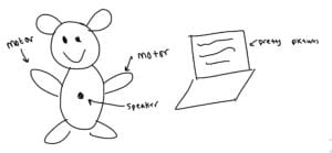
Everyone has one of those bad days that they just want to get over with. So my idea for this proposal is to create a project that detects the level of sadness you are in. It will detect the words you say to it and measure how sad you are. Then it will say some encouraging words to you. A stuffed animal will be there that you could hug and it will pat you. On the processing screen, it will also show something pretty that may help you calm down. Sometimes people do not want to tell others about what they are going through. This may be an alternative for helping them go through tuff times. 


Recitation 8: Serial Communication

Task #1:  Make a Processing Etch-A-Sketch:

First, I started with the Arduino portion. I used two Potentiometers, one controlling the x-axis and the other for the y-axis. I connected one to A0 and the other one to A1. 
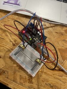
 

I found the Etch-A-Sketch created with Processing and Arduino was super interactive. By controlling two Potentiometers, I can create any drawings or pictures I desire. It was fun just messing around with it and seeing what was made. The interaction required the user to control the two Potentiometers turn them to certain degrees and make a drawing. One would control the x-axis and the other the y-axis. There was not much different from a regular Etch-A-Sketch, it was almost a perfect replica. 

Arduino Code:

#include "SerialRecord.h"

// Change this number to send a different number of values
SerialRecord writer(2);

void setup() {
  Serial.begin(9600);
  
}

void loop() {
  int sensorValue1 = analogRead(A0);
  int sensorValue2 = analogRead(A1);

  writer[0] = sensorValue1;
  writer.send();
  
  writer[1] = sensorValue2;
  writer.send();

  // This delay slows down the loop, so that it runs less frequently. This can
  // make it easier to debug the sketch, because new values are printed at a
  // slower rate.
  delay(10);
}

Processing Code:

import processing.serial.*;
import osteele.processing.SerialRecord.*;

Serial serialPort;
SerialRecord serialRecord;

float px;
float py;

void setup() {
  background(0);
  size(500, 500);

  String serialPortName = SerialUtils.findArduinoPort();
  serialPort = new Serial(this, serialPortName, 9600);

  // If the Arduino sketch sends a different number of values, modify the number
  // `2` on the next line to match the number of values that it sends.
  serialRecord = new SerialRecord(this, serialPort, 2);
  
  px = 0;
  py = 0;
}

void draw() {

  serialRecord.read();
  int value1 = serialRecord.values[0];
  int value2 = serialRecord.values[1];
  
  float x = map(value1, 0, 1024, 0, width);
  float y = map(value2, 0, 1024, 0, height);
  
  line(x, y, px, py);
  
  px = x;
  py = y;
  
  stroke(255);
}

For the Arduino Code, I did not change much from the original SerialMultipleValues sample code I used. Mainly, I took away the millis() code as it was not needed in this task. As the original code only supported one Potentiometer, I replicated the first code for the second Potentiometer. 

For the Processing Code, I used the original ReceiveMultipleValues as a basis. I first set up two other float values, px and py, which stand for previous x and previous y. I then set them both to the original value of zero, as they do not have a previous value yet. Lastly, I opted out circle() and used line() instead. Inside the line, x and y represents the point at which it is currently, and px and py, represents the last value the Potentiometer was at. 

Task #2:

Teammate: Jason Li

Similar to task 1, we started with the Arduino portion. We used the micro servo in both of our kits. We connected similarly to the Potentiometer, one to A0 and the other one to A1. 
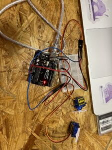
Compared to the Etch-A-Sketch, this one was less interactive. The user is not accomplishing anything. They just watch the ball bounce back and forth and the micromotor moves whenever the ball hits the edge of the screen. It would’ve been more interactive if the player was the one controlling the micromotor. 

Arduino Code:

#include "SerialRecord.h"

#include <Servo.h>

Servo left;  // create servo object to control a servo
Servo right;

int motor = -1;

// Change this number to the number of values you want to receive
SerialRecord reader(1);

void setup() {
  Serial.begin(9600);
  right.attach(A0);
  left.attach(A1);
}


void loop() {
  if (reader.read()) {
    motor = reader[0];
  }
  if (motor==1) {
    left.write(90);
    delay(500);
    left.write(0);
    motor = -1;
  }
  if (motor==0) {
    right.write(90);
    delay(500);
    right.write(0);
    motor = -1;
  }
}

Processing Code:

import processing.serial.*;
import osteele.processing.SerialRecord.*;

float x; 
float y;
float i=0;
boolean left = true;
boolean right = false;
int edge = 0;

// SoundFile sample;
Serial serialPort;
SerialRecord serialRecord;

void setup() {
  // sample = new SoundFile(this, "Ping Pong Table Tennis Sound Effect.mp3");
  // sample.loop();
  fullScreen();

  String serialPortName = SerialUtils.findArduinoPort();
  serialPort = new Serial(this, serialPortName, 9600);
  serialRecord = new SerialRecord(this, serialPort, 1);
  //serialRecord.logToCanvas(false);
}

void draw() {
  //println(frameRate);
  background(0);
  if (i<=0) {
    left = true;
    right = false;
  }
  if (i>=0.95*width && edge==0) {
    serialRecord.values[0] = 1;
    serialRecord.send();            // send it!
    edge = 1;
  }
  if (i<=0.05*width && edge==1) {
    serialRecord.values[0] = 0;
    serialRecord.send();            // send it!
    edge = 0;
  }
  if (i>=width) {
    right = true;
    left = false;
  }
  if (left==true) {
    i = lerp(i, 1.1*width, 0.02);
  }
  if (right==true) {
    i = lerp(i, -0.1*width, 0.02);
  }
  fill(255);
  circle(i, height/2, 70);
}

For the Arduino, I set one motor as right and the other motor as left. Then I created an integer motor and set the value equal to -1. When the SerialRecord Reader equals 1, the motor will also equal one. In this case, the left motor will move to hit the ball. Similarly, when the SerialRecord Readers equals 0, the motor will also equal to zero, causing the right motor to move. This was built off of the Sample code: ReceiveMultipleValues.

For the Processing Code, I implemented the sample SendMultipleValues code as my foundation. I first added the fullScreen () code in place of the size () code. Then I created multiple float, int, and boolean values. For this specific step, I asked the LA’s for help. I was getting frustrated and confused, but after spending time with them it finally worked. The main part that allows this code to work with Arduino is the part when i is between a certain value then the serialRecord value will be either 0 or 1. Which will be right or left for the Arduino. Making either the right or left motor move. We decided to use a lerp code to calculate the number between two numbers at a specific increment. I felt that this part of the recitation was the most challenging for us, as we used functions that we might not have learned in class. 


Final Project: Preparatory Research and Analysis

Research: 

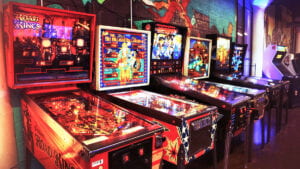
Growing up as a kid in Tampa, Florida. Every weekend, I would hit the arcade at Chuck-E-Cheese or any arcade shop near me. It has become a hobby, but also one of my first interactive experiences with interactive projects. Games versus any other type of media are considered one of the most interactive projects. The designer creates this world/game, which is further developed by the audience. I usually see online or even Douyin, of people taking a certain game, and its mechanics to a whole new level that the artist never even thought of. For the final project, I want to develop something similar to an arcade game. 

The first interactive project I would love to discuss is arcade games. Throughout the century, there have been thousands of arcade games developed to satisfy the imagination of the audience. Using a simple joystick and a couple of buttons, there are no limits to how great of a game you could make. Think about classical games such as Pac-man. Although it has become one of the oldest games out there, people still love it. Every time I see one, there is always an urge to hop on and play it. Each and every arcade game gives you a specific scenery and goal to complete. But how you complete that is totally up to the audience. That is the beauty of an arcade game, each person has their own way of completing the game. Interactive projects to me mean that they would interact with each audience differently. Another example is Mario, a classical game that has gone through many updates and is still very much played. The mechanics are not that complicated, but the audience has created their own way of playing it. They pull off impossible combos and moves, that awe me every time. So interactive project means for me something unique for each individual. I choose an arcade game as a reference because it is very similar to what we are currently doing. Pre-programming a game on Processing and using Arduino to control the development happening in Processing. I think an arcade game will be the true masterpiece and harmony between Processing and Arduino. 

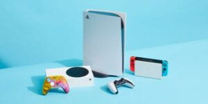
The second interactive project I looked into was console games. Console games, such as Wii, PS4, and Xbox have only really been around for a few decades. But the impact they have made on teenagers’ life can only be classified as life-changing. Every child now, growing up will probably have some sort of interaction with such devices. With just a few simple buttons on the controls themselves, the audience can create and play in a lot of different ways. With the introduction of VR games. The game world has in a way become the second world for the user. They are in a way physically interacting with the game world. Their every action and move will influence how they continue the game. It almost seems as if there are no more boundaries between the real world and the game world. It has become a full-body experience and interaction. Although we currently do not have the skills to create such lavish projects, it will still be very cool to incorporate some of the aspects from the console games into our final project. Using the Arduino as a medium between the controls and Processing. I believe creating something like that would be a very interactive project. 

My definition of an interactive project has never changed from the point I began this project. In successful interactive experiences, the core element of it is letting the user take control of their role. The creator should not limit what the user can do. There should be no set way to play it. No set way or perfect way to play the game. Everything should be up to the user to figure out. Take for example Genshin Impact. It created this fantastic world, the creator implemented some basic mechanisms that the user could use. But even in that, the user has continuously developed new mechanics and ways to play the game. Why these games are so popular and loved because it gives complete freedom to the user to do whatever they want. So a successful interactive experience should be letting the user experience the game the way they like, instead of being pointed out by the creator to every step they need to take. There was a quote in Art, Interaction and Engagement”, that I felt connected to. The quote goes as “the artist sets up
situations that develop in ways that are, at least in part, determined by the audience”. That to me is what I believe interaction should be. 

Work Cited: 

Art, Interaction and Engagement”: Provided by the professor. 


Recitation 7: Neopixel Music Visualization

Task #1: Test the NeoPixel

Step 1:

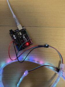
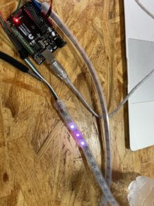
I connected the NeoPixel Led strip to the Arduino. The NeoPixel Led Strip had white, green, and red wires. I attached the white wire to GND, the green wire to D3, and the red wire to 5V.

Step 2:

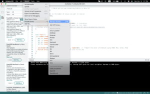
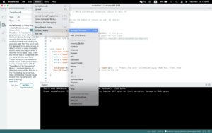
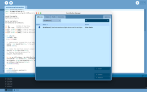
For this step, I downloaded the library that we would be using for this recitation. I went into Sketch -> Include library -> Manage libraries. Inside the library, I searched: fastLED and clicked install. 

Step 3:

In order to test if the NeoPixels are working, I used the FastLED/Blink found in the examples. 

Task #2: Use your computer to light up NeoPixels

Step 1:

For this step, I downloaded the SerialRecord to my Arduino. I selected from the menu Sketch -> Include library -> Manage libraries, and input SerialRecord.

I repeated this process on Processing too.

Step 2:

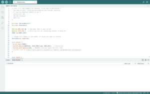
I programmed my Arduino using the code we made in class: IxLab_recitation7_ARDUINO.ino

I used the Serial Monitor to test whether the code worked or not. When using the Serial Monitor, the first digit will represent the pixel number. The second, third, and fourth digits represent the amount of red, green, and blue. After each number, there should also be a “,” between them. 


Step 3:

I used the code given in the recitation for this step: IxLab_recitation7_PROCESSING.pde

I closed the Serial Monitor that was currently running, or else this code will not work. It will show an error of “PORT BUSY”.

Task #3: Add Music!

Step 1:

I downloaded this sketch that was provided in the recitation. This sketch plays an audio file and analyzes the amplitude of the audio. From there we replaced beat.aiff with the song I choose. 

I went to this website: https://www.to-convert.com/en/diverse/youtube-to-mp3.php

I inputted the youtube link into this website and it automatically generated an mp3 version of it. From here I added this mp3 file to the folder that also held beat.aiff. I named the file Life.mp3 and I had another version of it titled Sad.mp3. I was testing this because I wanted to see if a bigger file would produce better-quality sound. But through this testing, they both sounded the same. 

Step 2:

For this step, I merged the code from the Processing sketch from Task #2 into the current one. The code simply just changes the colors when you drag the mouse back and forth. But for me, it did not seem to interact with the music enough. So I did some changes in Step 3.

Step 3:

I changed a few components from the original code. First, I changed the original rectangles that show up on the screen to circles. The code was similar but circles have three digits inside rather than four compared to rectangles. The major changes that I made to make it more interactive to the music were this part of the code:

 if (mousePressed == true) {
 
 }

Within this code, I made it so that when the volume is within a certain range the colors red, green, and blue with have this much value. For example, if the volume is between .1 and .2, red, green, and blue, will have a value of 50, 100, 50. So the whole song will have a different color coordinated with it based on how high or low the volume is. 

CODE:

import processing.sound.*;
import processing.serial.*;
import osteele.processing.SerialRecord.*;

SoundFile sample;
Amplitude analysis;

Serial serialPort;
SerialRecord serialRecord;

int W;         //width of the tiles
int NUM = 60;  //amount of pixels
int[] r = new int[NUM]; //red of each tile
int[] g = new int[NUM]; //red of each tile
int[] b = new int[NUM]; //red of each tile

void setup() {
  size(640, 480);
  W = width/NUM;
 
  // load and play a sound file in a loop
  sample = new SoundFile(this, "Life.mp3");
  sample.loop();

  // create the Amplitude analysis object
  analysis = new Amplitude(this);
  // analyze the playing sound file
  analysis.input(sample);
  
  String serialPortName = SerialUtils.findArduinoPort();
  serialPort = new Serial(this, serialPortName, 9600);
  serialRecord = new SerialRecord(this, serialPort, 4);
  serialRecord.logToCanvas(false);
  rectMode(CENTER);
}

void draw() {
  println(analysis.analyze());
  background(0);
  noStroke();
  fill(205, 120, 150);

  // analyze the audio for its volume level
  float volume = analysis.analyze();

  // volume is a number between 0.0 and 1.0
  // map the volume value to a useful scale
  float diameter = map(volume, 0, 1, 0, width);
  // draw a circle based on the microphone amplitude (volume)
  circle(width/2, height/2, diameter);
  
  for (int i=0; i<NUM; i ++) {
    fill(r[i], g[i], b[i]);
    circle(i * W + W/2, height/2, 10);
  }

 if (mousePressed == true) {
    int n = floor(constrain(mouseX/W , 0, NUM-1));
    if (volume < .1) {
      r[n] = floor(100);
      g[n] = floor(50);
      b[n] = floor(50);
    } else if (( volume >= .1) && volume < .2) {
      r[n] = floor(50);
      g[n] = floor(100);
      b[n] = floor(50);
    } else if ((volume >= .2) && volume < .3) {
      r[n] = floor(50);
      g[n] = floor(50);
      b[n] = floor(100);
    } else if (( volume >= .3) && volume < .4) {
      r[n] = floor(100);
      g[n] = floor(50);
      b[n] = floor(150);
    } else if (( volume >= .4) && volume < .5) {
      r[n] = floor(150);
      g[n] = floor(100);
      b[n] = floor(50);
    } else if (( volume >= .5) && volume < .6) {
      r[n] = floor(50);
      g[n] = floor(150);
      b[n] = floor(100);
    } else if ((volume >= .6) && volume < .7) {
      r[n] = floor(150);
      g[n] = floor(50);
      b[n] = floor(200);
    } else if ((volume >= .7) && volume < .8) {
      r[n] = floor(200);
      g[n] = floor(150);
      b[n] = floor(50);
    } else if ((volume >= .8) && volume < .9) {
      r[n] = floor(50);
      g[n] = floor(200);
      b[n] = floor(150);
    } else {
      r[n] = floor(100);
      g[n] = floor(200);
      b[n] = floor(250);
    }

    serialRecord.values[0] = n;     // which pixel we change (0-59)
    serialRecord.values[1] = r[n];  // how much red (0-255)
    serialRecord.values[2] = g[n];  // how much green (0-255)
    serialRecord.values[3] = b[n];  // how much blue (0-255)
    serialRecord.send();            // send it!
  }


}


Recitation 6: Animating an Interactive Poster

Recitation:
For the recitation part, I decided to make a hearts. Instead of using ellipses and triangles to make it, I decided to use bezierVertex() to draw my hearts. I think it was easier and less tedious to measure the coordinates out. 

CODE:

int value = 50;

void setup () {
  size(1024, 768);
}
void draw() {
  for (int y = 15; y < height; y= y + value) {
    for (int x = 50; x < width; x= x + value) {
      smooth();
      noStroke();
      fill(random(0, 255), random(0, 255), random(0, 255), 100);
    
      beginShape();
      vertex(x, y);
      bezierVertex(x, y - 20, x + 40, y - 10, x, y + 25);
      vertex(x, y);
      bezierVertex(x, y - 20, x - 40, y - 10, x, y + 25);
      endShape();
      delay(1);
    }
  }
}

Reflection:

I think the code bezierVertex() for me was the most useful thing I have learned so far in the recitation. It is really cool how simple and easy it is to make a shape. In a way I think I have grown to love the random function. It is so fun to make different colors. Furthermore, by adding another number after the three colors in fill, I can control the transparency of it. For my the hearts were changing colors too fast, so I simply added a delay() at the end to slow it down. Overall, in my opinion it was a success.

Homework:

For the IMA poster, I built on-top of what we did in our lecture class. 

CODE:

boolean mouseClicked = false;

void setup(){
  size(1024, 768);
}

void draw(){
  background();
    for (int x1 = 0; x1 < width+ 60; x1 = x1 + 60) {
    for (int y1 = 0; y1 < height + 60; y1 = y1 + 60) {
      smilie(x1, y1, random(1, 8));
  }
  
    }
    
    
   if (mouseClicked == true) {
    textSize(500);
    fill(random(0,255), random(0,255), random(0,255));
    text("IMA", 125, 550);
  }
}

void mouseClicked(){
  mouseClicked = true;
}

void background() {
  for (int i=0; i<height; i++){
    float b = map(i, 0, height, 255, 0);
    stroke(190, 150, b);    
    line(0, i, width, i);
  }
}

void smilie(int x, int y, float eyesize) {
  fill(random(0, 255), random(0, 255), random(0, 255), 150);
  stroke(10);
  ellipse(x, y, 50, 50);
  
  stroke(10);
  ellipse(x - 10, y - 10, eyesize, eyesize);
  ellipse(x + 10, y - 10, eyesize, eyesize);
  
  delay(1);
  
  stroke(10);
  noFill();
  arc(x, y, 35, 35, radians(45), radians(45+90));
  
}

Reflection:

This code for me was definitely a lot more complex. Originally I wanted the gradient to be diagonal, rather than it going just simply up and down. But I heard it was a lot more complex and difficult. So I reverted back to the simple gradient. I use the smilie code in our lecture class and added a few more touches. First I made the color of each smilie face randomized. Also, I made it transparent, so it will in a way blend with the background color. While coding the text, I did run into some problems. It didn’t seem to register whenever I clicked it. So I added a few more codes. In this case a boolean expression and a true/false function. I set my original mouseClicked = false, so whenever I click it, the statement will become true. This will lead to the word that I wrote down to appear. To make it even more colorful, I also made the IMA word change color. 

Conclusion:

I felt that this recitation was very fruitful, I learned boolean, true/false, and bezierVertex functions. With these I felt that I have a better and more deep understanding of Processing.