Circuit 1: Fade
To power up the Arduino UNO, I first connected the USB to my computer. The purpose of this circuit is for the light of the LED to fade from high to low. I first connected a wire from D9 to a resister. Then I connected the positive end of the LED light to the other end of the resister. To conclude the circuit, I connected a wire from GND on the Arduino UNO to the negative end of the LED light. By uploading the code on Arduino IDE to Arduino UNO, we complete this circuit.
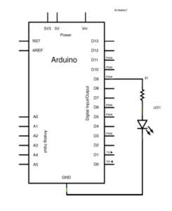
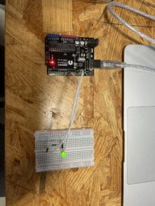
CODE:
void setup() {
// put your setup code here, to run once:
pinMode(9,OUTPUT);
pinMode(8,OUTPUT);
}
void loop() {
// put your main code here, to run repeatedly:
digitalWrite(9, HIGH);
delay(100);
digitalWrite(9, LOW);
delay(100);
// put your main code here, to run repeatedly:
digitalWrite(8, HIGH);
delay(1000);
digitalWrite(8, LOW);
delay(1000);
}
Circuit 2: toneMelody
For this circuit, we had to have the buzzer play a pre-coded melody. First, I connected a wire from D8 on the Arduino UNO to the negative end of the buzzer. Then I connected a wire from GND on the Arduino UNO to the positive end of the buzzer. To complete this circuit, I uploaded the Arduino IDE code to the Arduino UNO.
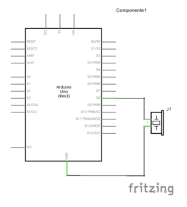
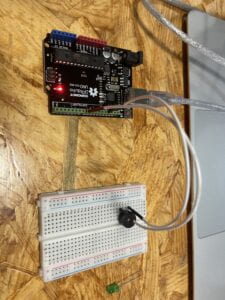
CODE:
“#include “pitches.h”
// notes in the melody:
int melody[] = {
NOTE_C4, NOTE_G3, NOTE_G3, NOTE_A3, NOTE_G3, 0, NOTE_B3, NOTE_C4
};
// note durations: 4 = quarter note, 8 = eighth note, etc.:
int noteDurations[] = {
4, 8, 8, 4, 4, 4, 4, 4
};
void setup() {
// iterate over the notes of the melody:
for (int thisNote = 0; thisNote < 8; thisNote++) {
// to calculate the note duration, take one second divided by the note type.
//e.g. quarter note = 1000 / 4, eighth note = 1000/8, etc.
int noteDuration = 1000 / noteDurations[thisNote];
tone(8, melody[thisNote], noteDuration);
// to distinguish the notes, set a minimum time between them.
// the note’s duration + 30% seems to work well:
int pauseBetweenNotes = noteDuration * 1.30;
delay(pauseBetweenNotes);
// stop the tone playing:
noTone(8);
}
}
void loop() {
// no need to repeat the melody.
}
Circuit 3: Speed Game
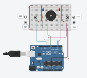
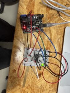
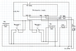
For circuit 3, we are tasked to build a simple game. To begin this circuit I started with wiring the Arduino UNO. First, I connected a USB from my computer to the Arduino UNO to establish a power source. Then I started by connecting all necessary wires to the Arduino UNO. I connected a wire to D2, D3, D8, D10, D11, GND, and 5V. I started building the circuit from left to right. I first connected the GND to the negative socket and 5V to the positive socket on the breadboard. Starting from the left side, I connected a back wire from one end of the negative socket to the other end of the negative socket on the breadboard. I also connected both of the positive ends together with a red wire. I set a button on the left end of the breadboard and connected a red wire from the positive power source to the button. Then, I connected the blue wire connected to D10 to the other side of the button. There I set a 10K resistor in between the button and the blue wire. Then I connected a black wire to the other end of the resistor to the negative power source on the top of the breadboard. Then, I placed a LED to the right of the resistor I placed down already. There I connected a resister vertically across the two sections of the breadboard while connecting it with the negative end of the LED light. Lastly, to complete the left side, I connected a black wire to the end of the resistor to the negative power source on the bottom. There I connected the blue wire on D2 on the Arduino UNO to the positive end of the LED light.
Continuing with the middle. I set a buzzer in the middle of the breadboard. I connected a green wire on D8 of the Arduino to the positive end of the buzzer and I used a black wire to connect the negative end of the buzzer to the negative power source on the bottom of the breadboard. For the right side, I repeated the same process as I did for the left side. After uploading the pre-coded code from Arduino IDE to Adruino UNO, we completed the little game.
I did run into a problem when I tried to upload the code into the Arduino UNO. As it failed to upload because I did not correctly select the board I needed to upload to. To fix this all I had to correct was to choose to connect the Arduino IDE to Arduino UNO. Problem solved.
CODE:
int buzzerPin = 8;
int button1 = 11;
int button2 = 10;
int led1 = 3;
int led2 = 2;
int goal = 10;
int buttonState1 = LOW;
int previousState1 = LOW;
int buttonState2 = LOW;
int previousState2 = LOW;
int counter1 = 0;
int counter2 = 0;
boolean winner1 = false;
boolean winner2 = false;
// the follow variables are long’s because the time, measured in miliseconds,
// will quickly become a bigger number than can be stored in an int.
long time = 0; // the last time the output pin was toggled
long debounce = 200; // the debounce time, increase if the output flickers
void setup() {
// put your setup code here, to run once:
Serial.begin(9600);
pinMode(buzzerPin, OUTPUT);
pinMode(button1, INPUT);
pinMode(button2, INPUT);
pinMode(led1, OUTPUT);
pinMode(led2, OUTPUT);
Serial.println(“******************* RACE THE LED *******************”);
delay(1000);
Serial.println(“READY”);
delay(1000);
Serial.println(“SET”);
delay(1500);
Serial.println(“GO!!!!!!!!!!!!!!!!”);
}
void loop() {
// put your main code here, to run repeatedly:
buttonState1 = digitalRead(button1);
buttonState2 = digitalRead(button2);
//Serial.println(buttonState1);
//this checks the times player 01 has pressed the button
if (counter1 < goal && winner2 == false) { if (buttonState1 != previousState1 && millis() – time > debounce) {
if (buttonState1 == HIGH) {
counter1++;
Serial.print(“player 01: “);
Serial.println(counter1);
time = millis();
}
}
previousState1 = buttonState1;
if (counter1 == goal && winner2 == false) {
winner1 = true;
digitalWrite(led1, HIGH);
Serial.println(“PLAYER 01 WINS”);
playMelody();
}
}
//this checks the times player 02 has pressed the button
if (counter2 < goal && winner1 == false) { if (buttonState2 != previousState2 && millis() – time > debounce) {
if (buttonState2 == HIGH) {
counter2++;
Serial.print(“player 02: “);
Serial.println(counter2);
time = millis();
}
}
previousState2 = buttonState2;
if (counter2 == goal && winner2 == false) {
winner2 = true;
digitalWrite(led2, HIGH);
Serial.println(“PLAYER 02 WINS”);
playMelody();
}
}
}
void playFreq(double freqHz, int durationMs) {
//Calculate the period in microseconds
int periodMicro = int((1 / freqHz) * 1000000);
int halfPeriod = periodMicro / 2;
//store start time
long startTime = millis();
//(millis() – startTime) is elapsed play time
while ((millis() – startTime) < durationMs) {
digitalWrite(buzzerPin, HIGH);
delayMicroseconds(halfPeriod);
digitalWrite(buzzerPin, LOW);
delayMicroseconds(halfPeriod);
}
}
void playMelody() {
playFreq(262, 100);
playFreq(294, 100);
playFreq(349, 100);
playFreq(294, 100);
playFreq(440, 200);
delay(100);
playFreq(440, 400);
playFreq(392, 400);
delay(300);
playFreq(262, 100);
playFreq(294, 100);
playFreq(349, 100);
playFreq(294, 100);
playFreq(392, 200);
delay(100);
playFreq(392, 400);
playFreq(349, 400);
}
Documentation Questions
Question 1: Propose another kind of creative button you could use in Circuit 3 to make the game more interactive. Read and use some material from the Physical Computing, Introduction Chapter (p. xvii – p. xxix) to explain why this button would make this game more interactive.
Answer 1: Another button that could be used could be our DIY pad we made in our first recitation class. Instead of pressing it fast enough, it could automatically generate a word, and whoever spells the word out first with morse code wins. This way there is a higher level of conversation between the physical world and the virtual world of the computer also known as transduction. The computer would have to recognize the word that the user is spelling and also have to compare it with the word it generated. It would make the game more interesting as it requires the user and the computer to recognize morse code. Instead of thoughtlessly pressing the button, the user has to actually think and carefully press it.
Question 2: Why did we use a 10 kOhm resistor with each push button? (Psssst… Go back to your slides for this answer)
Answer 2:When the button is not pressed, the resistor serves as a connection to the Ground. A pull-down resistor of 10 kOhm ensures we always read LOW when the button is not pressed
Question 3: In the book Getting Started with Arduino there is a clear description about the “Arduino Way” in chapter 2. Find a project that you find interesting that can be used as an example for these kind of projects. Cite it in adequate manner, include a picture, and explain the reasons that you chose it.
Answer 3: In people’s eyes trash or broken machines that are thrown away are just broken junk. To people who enjoy building or are curious, this is a cheap and easy outlet to learn. These machines or toys have gone through many experts’ hands before reaching the market. An example of this will be clocks. Simples clocks already have multiple components put together to make them work. Often or not the materials needed for a clock can be found in all sorts of machines and toys. When technology and higher-end programming are put into clocks it gets even more complex. Clocks are always around us and often times they only last for a time period before they get thrown away. They are an excellent source of materials for people to tinker with. With programming, it is even possible to add LED lights onto them and make them light up every set time period. The inside of clocks can be both a hard and easy thing to learn. As you learn more about clocks and their inner workings of them, when approaching higher levels of machines it will become easier to understand them. Furthermore, clocks come in all different sizes. The alarm next to our bed, the clock on the wall, the clock on your wrist. They all have intricate designs in them and are there for us to learn when taken apart.

Looking inside Clocks, http://www.bowerswatchandclockrepair.com/lookinginsideaclock.htm.