Task 1: Build the circuits
Step 1:
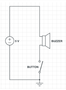
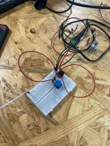
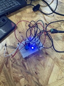
The goal of this circuit is to make the buzzer beep, whenever the button is pressed. First, we connected the power source to the board, with the red wire to the positive and the black wire to the negative. We set the buzzer on the breadboard. We then established a connection from the power to the buzzer. We did this by connecting a green wire to the positive below the red power wire. From there we connected the other end of the green wire to the positive side of the buzzer. We then tried to establish a connection between the power and the buzzer. We set the buzzer on the breadboard. We connected a red wire below the black power wire and connected the other end of the red wire to the negative part of the button. Lastly, we used a red wire to connect the button to the buzzer to complete the circuit. Our circuit did end up working in the end. We had some issues starting off the project. Mainly we did not connect components together with wires, which was what caused it to fail initially. To solve the issue, we used our hands to track where the power went just to make sure everything was linked together.
Step 2:
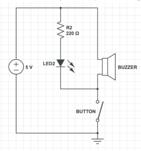
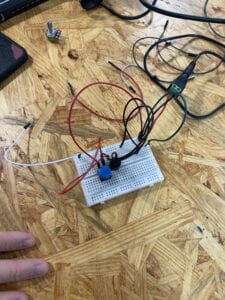
Step two was built on top of step one. This step also required the buzzer to beep, whenever the button was pressed. On top of that, a LED light was also required to light up when the button was pressed. First, we established a connection between the resistor and the power source. We set the resistor at the end of the breadboard and connected one side of it with the positive power with a green wire. With that established we connected a LED light to the other end of the resistor. Since the other side of the resistor is connected to the positive side, we set the shorter end of the LED light (negative side) to the resistor. Lastly, we connected the longer end of the LEd light (positive side) to the buzzer with a black wire. With the last touch, we completed this circuit. In this step, we experienced fewer errors compared to step 1. We did, however, moved the buzzer and button around as, because we wanted everything to be spaced out.
Step 3:
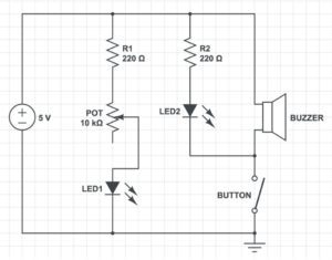
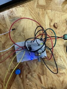
Step 3 is built on the previous two steps. This step required the buzzer and LED to light up, whenever the button is pressed. Furthermore, it also required a LED to be constantly lit, and a potentiometer (POT) which changes the brightness of the LED light with the change in the resistance with the nob. We first set a connection with a resistor to the power source. At first, we used a red wire to connect one side of the power source to the other side of the power source. This way both sides of the positive power source on the ends of the breadboard could be used. From there we connected a black wire to connect one end of the resistor to the positive end of the breadboard. We then connected the other side of the resistor to the right end of the POT. Following that we tried to establish a connection between the LED light and the POT. We connected a black wire to the middle of the POT to the positive end of the LED light. To finish it off we used a white wire to connect the negative end of the LED light to the negative power source. We also had little issues with step 3. We paid extra attention to make sure all the wires are connected to the right power source and the right positive or negative ends.
Task 2: Build a switch
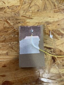
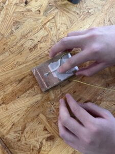
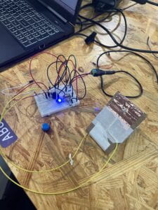
After receiving all our materials we first prepared our wire. We stripped both ends of our wire to expose the wire in it. We then took the copper tape and wrapped it around one end of our cardboard. We then took our stripped wire and bent it so that the exposed wire sits directly on the copper tape. We then took the tape to tape the wire down to the board. Furthermore, while doing these steps we heat up our soldering iron to around 700 degrees. We each took a soldering stick (a metal stick) and test out the soldering iron to see if it is hot enough. We then laid the soldering iron on both the copper tape and wire to heat them up. Then we slowly fed the soldering stick into the soldering iron so it can melt onto the wire and copper tape. What I had the most difficult time with was the soldering part. I did not spread the metal around and it became a lump of metal after only a second of cooling. To fix this I took some more soldering sticks and heat up that and the metal that was original on my board. Which in the end fixed the issue. In the end, it formed a pool around my wire and copper tape, that firmly attached them together. After my partner and I completed both of our switches, we taped them together to form a full switch.
Task 3: Switch the switches and send a message
This task included all the steps listed in task 1. First, we took out the button that was on the board. Then we took the two wires on our switch and subbed them in for where the button’s original position on the breadboard was. One wire is connected to the negative power source and the other is connected to the positive power source. Lastly, my partner thought of a word to send me in morse code. I was able to guess the word that he sent was MATH.
Additional Required Questions:
Question 1: What is the function of the resistor R1? (You can read about the reason why LEDs need resistors here)
Answer 1: It is necessary to use resistors in LEDs so that they do not get damaged by current flowing through them. Resistors are able to limit the current to below the maximum allowable current that LEDs are capable of handling. Resistors function as a limiter so that LEDs do not exert more currents than is allowed.
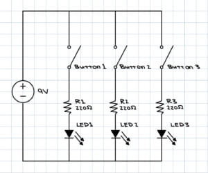
Question 2: Looking at the following circuit, draw its diagram by yourself.

Answer 2:
Question 3: After reading The Art of Interactive Design, in what way do you think that the circuit you built today includes interactivity? Which degree of interactivity does it possess? Please explain your answer.
Answer 3: The circuit we built today defiantly has a degree of interactivity. As said in the article everything can have interactivity but the degree of interactivity varies. Our circuit includes interactivity because it gives a response whenever we push on the button similar to how the light of a refrigerator has interactivity. I would say that the circuit we build today would have low interactivity. Besides a beep and LED lighting up with every press of the button, there is not much else. The circuit does not offer more than a couple of options similar to the light of the fridge.
Question 4: How can Interaction Design and Physical Computing be used to create Interactive Art? You can reference Zack Lieberman’s video or any other artists that you know.
Answer 4: The first project that Zack Lieberman talked about was “Drawn”. In this project, after individuals have drawn whatever they desired they have the ability to interact with their artwork, by moving whatever was drawn around. The second project that Zack Liberman talked about was “Iq Font”. It was very interesting how he was able to program a computer to follow the car, and through that make a font that was unique to the car. The last project that was discussed was called “EyeWriter”. It was fascinating how they were able to program this low-cost software and eye tractor for the man with Liguria disease. Through only his eyes, he was able to draw and create artwork. All these interactive arts are made through interaction design and physical computing, which makes it possible that whoever comes in contact with them, is physically able to interact with them and make art.