Recitation 2: Arduino Basics

Circuit 1: Fade

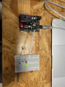
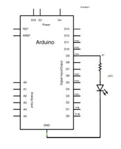
To power up the Arduino UNO, I first connected the USB to my computer. The purpose of this circuit is for the light of the LED to fade from high to low. I first connected a wire from D9 to a resister. Then I connected the positive end of the LED light to the other end of the resister. To conclude the circuit, I connected a wire from GND on the Arduino UNO to the negative end of the LED light. By uploading the code on Arduino IDE to Arduino UNO, we complete this circuit. 
         

CODE:

void setup() {
// put your setup code here, to run once:
pinMode(9,OUTPUT);
pinMode(8,OUTPUT);
}

void loop() {
// put your main code here, to run repeatedly:
digitalWrite(9, HIGH);
delay(100);
digitalWrite(9, LOW);
delay(100);
// put your main code here, to run repeatedly:
digitalWrite(8, HIGH);
delay(1000);
digitalWrite(8, LOW);
delay(1000);
}

Circuit 2: toneMelody

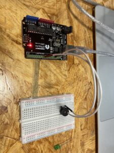
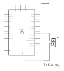
For this circuit, we had to have the buzzer play a pre-coded melody. First, I connected a wire from D8 on the Arduino UNO to the negative end of the buzzer. Then I connected a wire from GND on the Arduino UNO to the positive end of the buzzer. To complete this circuit, I uploaded the Arduino IDE code to the Arduino UNO. 
         

CODE:

“#include “pitches.h”

// notes in the melody:
int melody[] = {
NOTE_C4, NOTE_G3, NOTE_G3, NOTE_A3, NOTE_G3, 0, NOTE_B3, NOTE_C4
};

// note durations: 4 = quarter note, 8 = eighth note, etc.:
int noteDurations[] = {
4, 8, 8, 4, 4, 4, 4, 4
};

void setup() {
// iterate over the notes of the melody:
for (int thisNote = 0; thisNote < 8; thisNote++) {

// to calculate the note duration, take one second divided by the note type.
//e.g. quarter note = 1000 / 4, eighth note = 1000/8, etc.
int noteDuration = 1000 / noteDurations[thisNote];
tone(8, melody[thisNote], noteDuration);

// to distinguish the notes, set a minimum time between them.
// the note’s duration + 30% seems to work well:
int pauseBetweenNotes = noteDuration * 1.30;
delay(pauseBetweenNotes);
// stop the tone playing:
noTone(8);
}
}

void loop() {
// no need to repeat the melody.
}

Circuit 3: Speed Game

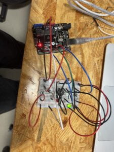
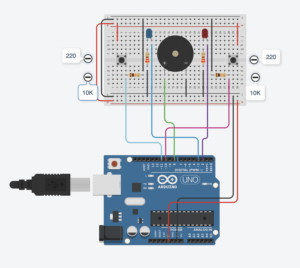
For circuit 3, we are tasked to build a simple game. To begin this circuit I started with wiring the Arduino UNO. First, I connected a USB from my computer to the Arduino UNO to establish a power source. Then I started by connecting all necessary wires to the Arduino UNO. I connected a wire to D2, D3, D8, D10, D11, GND, and 5V. I started building the circuit from left to right. I first connected the GND to the negative socket and 5V to the positive socket on the breadboard. Starting from the left side, I connected a back wire from one end of the negative socket to the other end of the negative socket on the breadboard. I also connected both of the positive ends together with a red wire. I set a button on the left end of the breadboard and connected a red wire from the positive power source to the button. Then, I connected the blue wire connected to D10 to the other side of the button. There I set a 10K resistor in between the button and the blue wire. Then I connected a black wire to the other end of the resistor to the negative power source on the top of the breadboard. Then, I placed a LED to the right of the resistor I placed down already. There I connected a resister vertically across the two sections of the breadboard while connecting it with the negative end of the LED light. Lastly, to complete the left side, I connected a black wire to the end of the resistor to the negative power source on the bottom. There I connected the blue wire on D2 on the Arduino UNO to the positive end of the LED light. 

Continuing with the middle. I set a buzzer in the middle of the breadboard. I connected a green wire on D8 of the Arduino to the positive end of the buzzer and I used a black wire to connect the negative end of the buzzer to the negative power source on the bottom of the breadboard. For the right side, I repeated the same process as I did for the left side. After uploading the pre-coded code from Arduino IDE to Adruino UNO, we completed the little game. 

I did run into a problem when I tried to upload the code into the Arduino UNO. As it failed to upload because I did not correctly select the board I needed to upload to. To fix this all I had to correct was to choose to connect the Arduino IDE to Arduino UNO. Problem solved. 
         

CODE:

int buzzerPin = 8;
int button1 = 11;
int button2 = 10;
int led1 = 3;
int led2 = 2;

int goal = 10;
int buttonState1 = LOW;
int previousState1 = LOW;
int buttonState2 = LOW;
int previousState2 = LOW;

int counter1 = 0;
int counter2 = 0;
boolean winner1 = false;
boolean winner2 = false;

// the follow variables are long’s because the time, measured in miliseconds,
// will quickly become a bigger number than can be stored in an int.
long time = 0; // the last time the output pin was toggled
long debounce = 200; // the debounce time, increase if the output flickers

void setup() {
// put your setup code here, to run once:
Serial.begin(9600);
pinMode(buzzerPin, OUTPUT);
pinMode(button1, INPUT);
pinMode(button2, INPUT);
pinMode(led1, OUTPUT);
pinMode(led2, OUTPUT);
Serial.println(“******************* RACE THE LED *******************”);
delay(1000);
Serial.println(“READY”);
delay(1000);
Serial.println(“SET”);
delay(1500);
Serial.println(“GO!!!!!!!!!!!!!!!!”);

}

void loop() {
// put your main code here, to run repeatedly:
buttonState1 = digitalRead(button1);
buttonState2 = digitalRead(button2);
//Serial.println(buttonState1);

//this checks the times player 01 has pressed the button
if (counter1 < goal && winner2 == false) { if (buttonState1 != previousState1 && millis() – time > debounce) {
if (buttonState1 == HIGH) {
counter1++;
Serial.print(“player 01: “);
Serial.println(counter1);
time = millis();
}
}
previousState1 = buttonState1;
if (counter1 == goal && winner2 == false) {
winner1 = true;
digitalWrite(led1, HIGH);
Serial.println(“PLAYER 01 WINS”);
playMelody();
}
}

//this checks the times player 02 has pressed the button

if (counter2 < goal && winner1 == false) { if (buttonState2 != previousState2 && millis() – time > debounce) {
if (buttonState2 == HIGH) {
counter2++;
Serial.print(“player 02: “);
Serial.println(counter2);
time = millis();
}
}
previousState2 = buttonState2;
if (counter2 == goal && winner2 == false) {
winner2 = true;
digitalWrite(led2, HIGH);
Serial.println(“PLAYER 02 WINS”);
playMelody();
}
}

}

void playFreq(double freqHz, int durationMs) {
//Calculate the period in microseconds
int periodMicro = int((1 / freqHz) * 1000000);
int halfPeriod = periodMicro / 2;

//store start time
long startTime = millis();

//(millis() – startTime) is elapsed play time
while ((millis() – startTime) < durationMs) {
digitalWrite(buzzerPin, HIGH);
delayMicroseconds(halfPeriod);
digitalWrite(buzzerPin, LOW);
delayMicroseconds(halfPeriod);
}
}

void playMelody() {

playFreq(262, 100);
playFreq(294, 100);
playFreq(349, 100);
playFreq(294, 100);
playFreq(440, 200);
delay(100);
playFreq(440, 400);
playFreq(392, 400);
delay(300);
playFreq(262, 100);
playFreq(294, 100);
playFreq(349, 100);
playFreq(294, 100);
playFreq(392, 200);
delay(100);
playFreq(392, 400);
playFreq(349, 400);

}

Documentation Questions 

Question 1: Propose another kind of creative button you could use in Circuit 3 to make the game more interactive. Read and use some material from the Physical Computing, Introduction Chapter (p. xvii – p. xxix) to explain why this button would make this game more interactive.

Answer 1: Another button that could be used could be our DIY pad we made in our first recitation class. Instead of pressing it fast enough, it could automatically generate a word, and whoever spells the word out first with morse code wins. This way there is a higher level of conversation between the physical world and the virtual world of the computer also known as transduction. The computer would have to recognize the word that the user is spelling and also have to compare it with the word it generated. It would make the game more interesting as it requires the user and the computer to recognize morse code. Instead of thoughtlessly pressing the button, the user has to actually think and carefully press it. 

Question 2: Why did we use a 10 kOhm resistor with each push button? (Psssst… Go back to your slides for this answer)

Answer 2:When the button is not pressed, the resistor serves as a connection to the Ground. A pull-down resistor of 10 kOhm ensures we always read LOW when the button is not pressed

Question 3: In the book Getting Started with Arduino there is a clear description about the “Arduino Way” in chapter 2. Find a project that you find interesting that can be used as an example for these kind of projects. Cite it in adequate manner, include a picture, and explain the reasons that you chose it.

Answer 3: In people’s eyes trash or broken machines that are thrown away are just broken junk. To people who enjoy building or are curious, this is a cheap and easy outlet to learn. These machines or toys have gone through many experts’ hands before reaching the market. An example of this will be clocks. Simples clocks already have multiple components put together to make them work. Often or not the materials needed for a clock can be found in all sorts of machines and toys. When technology and higher-end programming are put into clocks it gets even more complex. Clocks are always around us and often times they only last for a time period before they get thrown away. They are an excellent source of materials for people to tinker with. With programming, it is even possible to add LED lights onto them and make them light up every set time period. The inside of clocks can be both a hard and easy thing to learn. As you learn more about clocks and their inner workings of them, when approaching higher levels of machines it will become easier to understand them. Furthermore, clocks come in all different sizes. The alarm next to our bed, the clock on the wall, the clock on your wrist. They all have intricate designs in them and are there for us to learn when taken apart. 

Looking inside Clocks, http://www.bowerswatchandclockrepair.com/lookinginsideaclock.htm.
Research Project: Read

READ

Title: Imaginative Gear 

In “Veldt”, audiences are presented with this changing room that changes with the user’s imagination. My idea for this story is what I call the Imaginative Gear, which similar to the changing room, has the ability to change your clothes that is the best fit for the environment. It also has the capability to sense danger based on the user’s reactions and form a protective barrier to protect them from harm. It also has the ability to change based on your mood and emotion, or even your imaginative system. You can literally create a new type of clothing with simply an idea in your head. There are currently no such inventions currently present in real life. There is clothing that does change but those are all very limited to only a few types of changes. This type of invention first has to solve the issue of the mass amount of materials needed to deal with all kinds of environments. Since different scenarios and environments need specific gear to protect them from harm. Only when a universal material is found, can this project truly can be complete. 

Title: Remover

In “The Ones Who Walks Away From Omelas”, the story is set during a summer festival in a utopian city known as Omelas. The prosperity of Omelas depends on the perpetual misery of a single child. My idea for this story is called the remover. While instead of everyone’s happiness relying a single on the misery of a single child, why not create a gear that absorbs the negative emotions and misery of a person? A sensor will be built throughout the city, when it detects sadness or misery, it would send electrical waves to remove such emotions. Every person’s emotion creates different wavelengths, and while the machine absorbs wavelengths it will present them on a big wall. At the end of the day, an artwork is presented in the middle of the city showing all the wavelengths together. It is a way of making sad emotions into a form of art that heals the individuals who look at it, as they could be part of the making of such art. To collect such wavelengths, there are already machines available to collect such data. There has been no current invention that could remove negative emotions from an individual. Some issue that this type of interactive artifact can have is how it will affect the brain negatively. 

Title: Immersion

In “The Plague”, people are becoming statues, yet in another sense, their brain is still active and considered alive. My idea is to create a digital platform, where an individual’s brain is uploaded onto the digital platform and continues living there. Instead of being trapped in their stone body and having the risk of being killed or thrown out, this will in sense let them keep living but in data form. A technology that connects to this invention is VR gear. It brings the user into the game or environment of their choice. Although your brain is not completely in the system, it achieves the idea more or less. As uploading a person’s consciousness into a digital world is riskier and requires a lot more programming compared to VR gear. In this digital world, people can interact with everything that is part of the system. They can live how they desire and perform actions of their choice. It is merely a platform for those that have been affected by the disease to have a second chance at life. An issue with this invention is maintenance. If in theory everyone on earth gets affected by the disease there would be no one able to update and keep the world in check. 

Research Project: Research

RESEARCH

Interaction: A collaboration between artist and audience. It is an instrument or environment that the audience takes part in, with minimal interference from the artist. It is an outlet or interaction between the artist and the audience. It is a performance between artist and audience, that allows the audience to create artwork the way they desire. Interaction should be unpredictable rather than a set code that does events on repeat. 

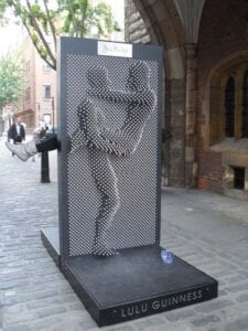
Interactive Art Project: A great example of an interactive art project is pin arts. It is an instrument that the audience can physically take part in. It requires little to no interference from the artist or user that created it. Pin arts can either be big or small. The size and concentration of the pin board all depend on the artist and observer. Through the pinboard, the audience can design and create any image they desire. There is no set or correct image that should be created, it is all based on how the audience interacts with the instrument. This is why pin arts are unpredictable as no two pin boards could in theory be the same. As different users would create different artworks that are outside the initial idea in the creator’s head. Pin arts triggered my idea of interaction because the first time I had interactions with it, there were no instructions handed to me. It was almost similar to an invisible force making my hands or face push the pins on the board. It required me to have no interaction with the artist besides the instrument he/she created. What should be used is available to us users, and what should not be used is not included or blocked off. Pin art is a fun way to relax and make realistic art at the same time. When the first user makes art from it and leave, the second user will come around and make a new one. This cycle repeats endlessly. When pin art is magnified and put in public, it sprouts interactivity with people on the street. Since the pinboards have two sides, there could be a person standing on both sides and pressing at them at the same time. 


https://no.pinterest.com/pin/450782243938274568/?mt=login  

https://no.pinterest.com/pin/450782243938288781/?mt=login&nic_v3=1a1gJfLcJ

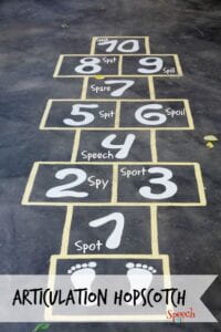
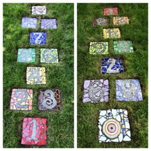
Non-interactive art project: A idea of non-interactive art project would be hopscotch. Hopscotch does not fit into the definition of interaction because every sequence done by the user follows a set code that is unchangeable. It is a pre-drawn sequence by the artist that the user follows over and over again until it is changed. Hopscotch is similar to the refrigerator light example. No matter how many times you open the refrigerator, the only goal of the light is to open when the refrigerator is opened. Hopscotch follows an order either land with one leg when there is one square or land with two legs when there are two squares. Put squares together and you have a game of hopscotch, which is not really interactive at all as it only follows a set code rather than it being unpredictable. 


https://no.pinterest.com/pin/6473993207091806/?nic_v3=1a1gJfLcJ 

https://no.pinterest.com/pin/62909726029533372/?nic_v3=1a1gJfLcJ

Recitation Documentation 1: Electronics & Soldering

Task 1: Build the circuits 

Step 1:

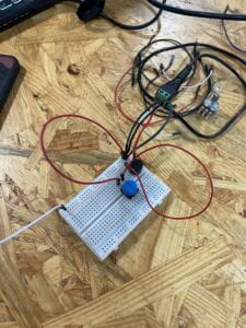
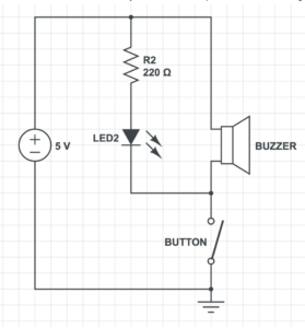
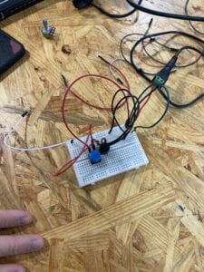
The goal of this circuit is to make the buzzer beep, whenever the button is pressed. First, we connected the power source to the board, with the red wire to the positive and the black wire to the negative. We set the buzzer on the breadboard. We then established a connection from the power to the buzzer. We did this by connecting a green wire to the positive below the red power wire. From there we connected the other end of the green wire to the positive side of the buzzer. We then tried to establish a connection between the power and the buzzer. We set the buzzer on the breadboard. We connected a red wire below the black power wire and connected the other end of the red wire to the negative part of the button. Lastly, we used a red wire to connect the button to the buzzer to complete the circuit. Our circuit did end up working in the end. We had some issues starting off the project. Mainly we did not connect components together with wires, which was what caused it to fail initially. To solve the issue, we used our hands to track where the power went just to make sure everything was linked together. 


Step 2:

Step two was built on top of step one. This step also required the buzzer to beep, whenever the button was pressed. On top of that, a LED light was also required to light up when the button was pressed. First, we established a connection between the resistor and the power source. We set the resistor at the end of the breadboard and connected one side of it with the positive power with a green wire. With that established we connected a LED light to the other end of the resistor. Since the other side of the resistor is connected to the positive side, we set the shorter end of the LED light (negative side) to the resistor. Lastly, we connected the longer end of the LEd light (positive side) to the buzzer with a black wire. With the last touch, we completed this circuit. In this step, we experienced fewer errors compared to step 1. We did, however, moved the buzzer and button around as, because we wanted everything to be spaced out. 


Step 3:

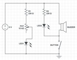
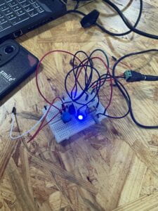
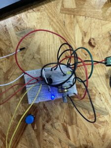
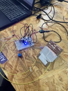
Step 3 is built on the previous two steps. This step required the buzzer and LED to light up, whenever the button is pressed. Furthermore, it also required a LED to be constantly lit, and a potentiometer (POT) which changes the brightness of the LED light with the change in the resistance with the nob. We first set a connection with a resistor to the power source. At first, we used a red wire to connect one side of the power source to the other side of the power source. This way both sides of the positive power source on the ends of the breadboard could be used. From there we connected a black wire to connect one end of the resistor to the positive end of the breadboard. We then connected the other side of the resistor to the right end of the POT. Following that we tried to establish a connection between the LED light and the POT. We connected a black wire to the middle of the POT to the positive end of the LED light. To finish it off we used a white wire to connect the negative end of the LED light to the negative power source. We also had little issues with step 3. We paid extra attention to make sure all the wires are connected to the right power source and the right positive or negative ends. 


Task 2: Build a switch

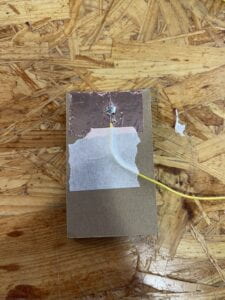
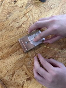
After receiving all our materials we first prepared our wire. We stripped both ends of our wire to expose the wire in it. We then took the copper tape and wrapped it around one end of our cardboard. We then took our stripped wire and bent it so that the exposed wire sits directly on the copper tape. We then took the tape to tape the wire down to the board. Furthermore, while doing these steps we heat up our soldering iron to around 700 degrees. We each took a soldering stick (a metal stick) and test out the soldering iron to see if it is hot enough. We then laid the soldering iron on both the copper tape and wire to heat them up. Then we slowly fed the soldering stick into the soldering iron so it can melt onto the wire and copper tape. What I had the most difficult time with was the soldering part. I did not spread the metal around and it became a lump of metal after only a second of cooling. To fix this I took some more soldering sticks and heat up that and the metal that was original on my board. Which in the end fixed the issue. In the end, it formed a pool around my wire and copper tape, that firmly attached them together. After my partner and I completed both of our switches, we taped them together to form a full switch. 


Task 3: Switch the switches and send a message

This task included all the steps listed in task 1. First, we took out the button that was on the board. Then we took the two wires on our switch and subbed them in for where the button’s original position on the breadboard was. One wire is connected to the negative power source and the other is connected to the positive power source. Lastly, my partner thought of a word to send me in morse code. I was able to guess the word that he sent was MATH. 


Additional Required Questions:

Question 1: What is the function of the resistor R1? (You can read about the reason why LEDs need resistors here

Answer 1: It is necessary to use resistors in LEDs so that they do not get damaged by current flowing through them. Resistors are able to limit the current to below the maximum allowable current that LEDs are capable of handling. Resistors function as a limiter so that LEDs do not exert more currents than is allowed. 

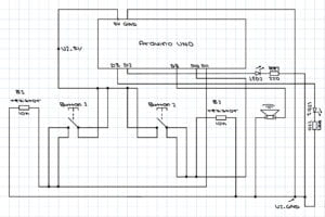
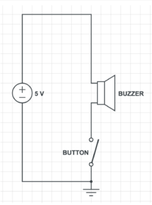
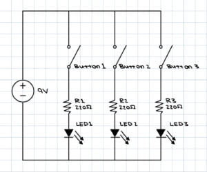
Question 2:  Looking at the following circuit, draw its diagram by yourself.

Answer 2:

Question 3: After reading The Art of Interactive Design, in what way do you think that the circuit you built today includes interactivity? Which degree of interactivity does it possess? Please explain your answer.

Answer 3: The circuit we built today defiantly has a degree of interactivity. As said in the article everything can have interactivity but the degree of interactivity varies. Our circuit includes interactivity because it gives a response whenever we push on the button similar to how the light of a refrigerator has interactivity. I would say that the circuit we build today would have low interactivity. Besides a beep and LED lighting up with every press of the button, there is not much else. The circuit does not offer more than a couple of options similar to the light of the fridge. 

Question 4: How can Interaction Design and Physical Computing be used to create Interactive Art? You can reference Zack Lieberman’s video or any other artists that you know.

Answer 4: The first project that Zack Lieberman talked about was “Drawn”. In this project, after individuals have drawn whatever they desired they have the ability to interact with their artwork, by moving whatever was drawn around. The second project that Zack Liberman talked about was “Iq Font”. It was very interesting how he was able to program a computer to follow the car, and through that make a font that was unique to the car. The last project that was discussed was called “EyeWriter”. It was fascinating how they were able to program this low-cost software and eye tractor for the man with Liguria disease. Through only his eyes, he was able to draw and create artwork. All these interactive arts are made through interaction design and physical computing, which makes it possible that whoever comes in contact with them, is physically able to interact with them and make art. 

Hello world!

Welcome to Web Publishing @ NYU. This is your first post. Edit or delete it, then start creating your site!

Online help is available via the Web Publishing Knowledge Site (wp.nyu.edu/knowledge) and the ServiceLink knowledge base (www.nyu.edu/servicelink). Through ServiceLink, you can find step-by-step instructions, as well as tutorials.

Digital Accessibility

As content creators who create and publish text, images, video, and audio, you must adhere to the NYU Website Accessibility Policy (https://www.nyu.edu/digitalaccessibility/policy) when creating and publishing digital content.

Web Publishing-specific Digital Accessibility Best Practices and examples of how to ensure your content are compliant are available at https://wp.nyu.edu/digitalaccessibility

If you have additional questions, contact the IT Service Desk for assistance. Support is available 24/7/365. For more details, visit www.nyu.edu/it/servicedesk.