One-man Band – Raphael & Jennifer – Instructor: Eric
I
CONCEPTION AND DESIGN
Our journey began with a deep admiration for renowned loop station performances, where artists expertly employ synthesizers to loop segments of their own compositions. This innovative approach transforms a solo musician into a symphony, creating the illusion of a full ensemble with just one performer. A prime example of such a performance can be witnessed in this Loop Station show (starting at 0:42): https://youtu.be/f61mC3XbJtw?feature=shared.
However, mastering this form of artistry demands significant instrumental prowess, a skill not everyone possesses. Recognizing this, many have turned to a more accessible form of solo performance, predominantly through the use of the software “Library Band”. This method, while less challenging in terms of instrumental expertise, still requires a knack for arranging and is limited to online creation, lacking the vibrancy of live shows.
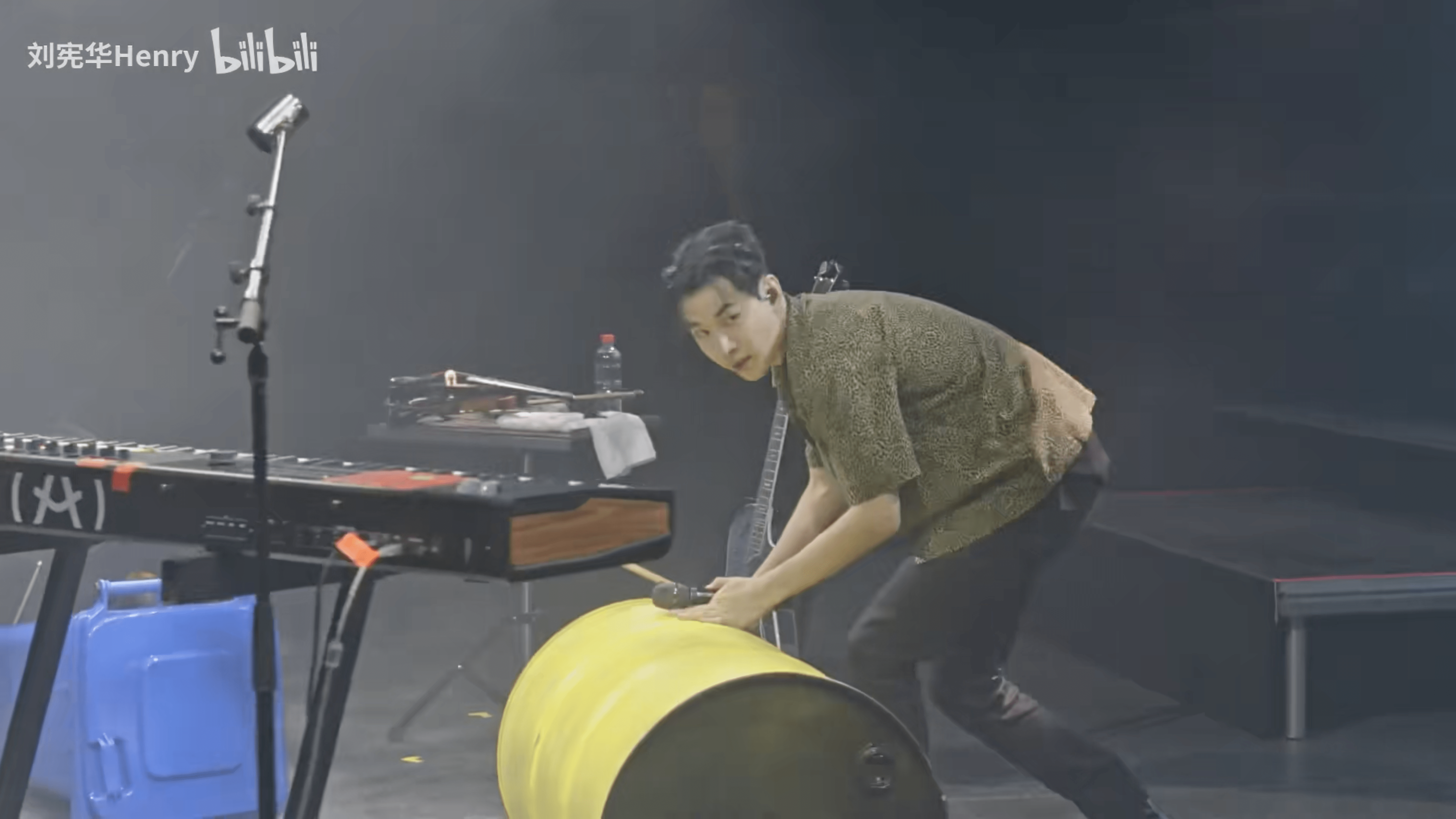
In response to these limitations, we envisioned a unique solution. Our goal was to merge the intricate art of loop station performances with the user-friendly nature of “Library Band”. We aimed to design a one-man-band program that lowers the barrier to entry in terms of instrumental skills, while simultaneously offering a variety of instrumental effects. Most importantly, our program facilitates live arrangements and performances. This integration not only makes the one-man-band experience more accessible but also preserves the dynamic and interactive essence of live music, opening doors for more individuals to explore and enjoy the art of solo performances.
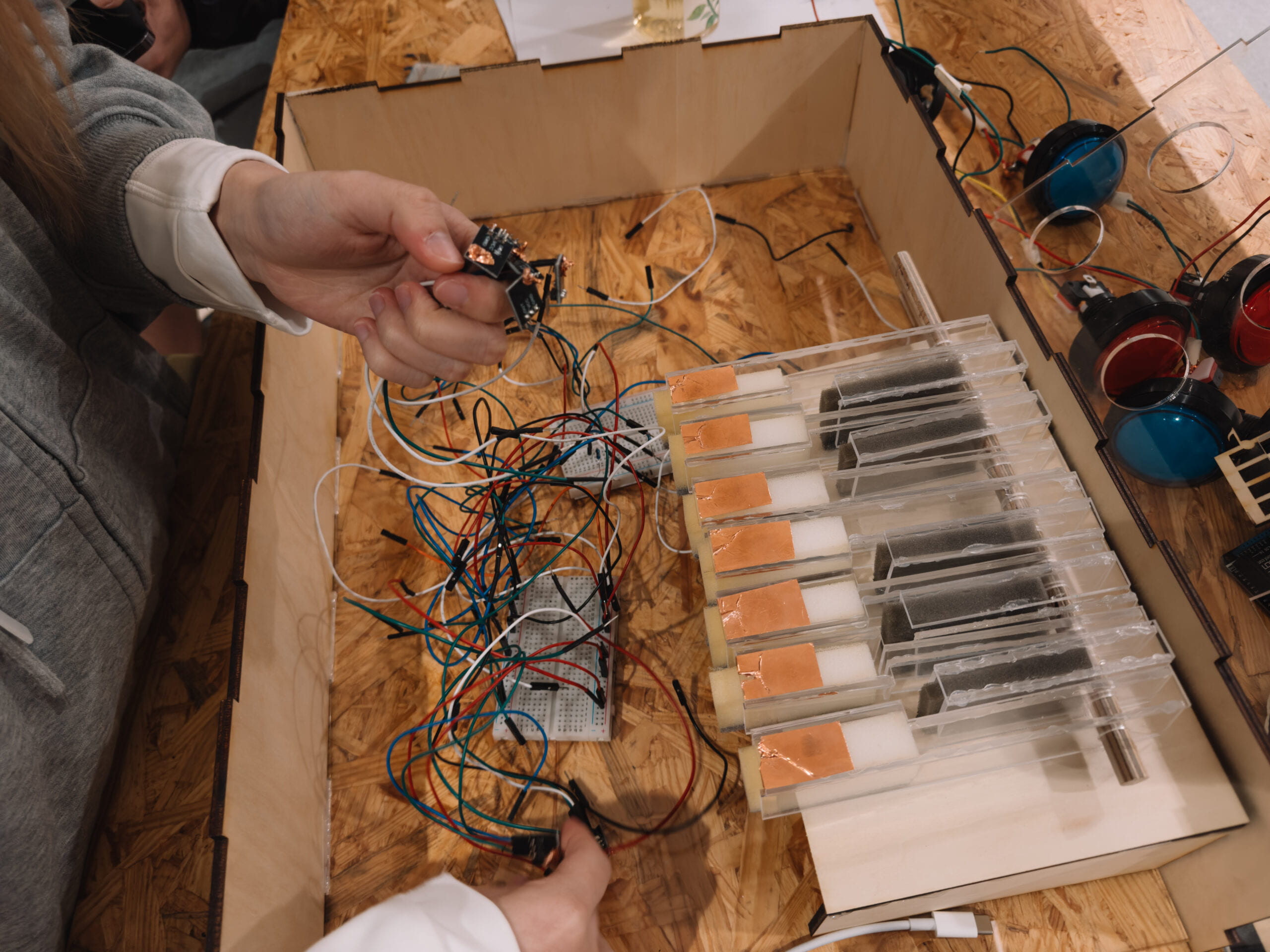
In our design, we strategically divided the entire setup into three distinct sections to create an efficient and intuitive interface. The first section is the keyboard area, crafted with transparent acrylic and integrated with capacitive sensors. This combination provides a modern and functional playing experience. The sensors accurately capture each touch, transforming it into melodious music.
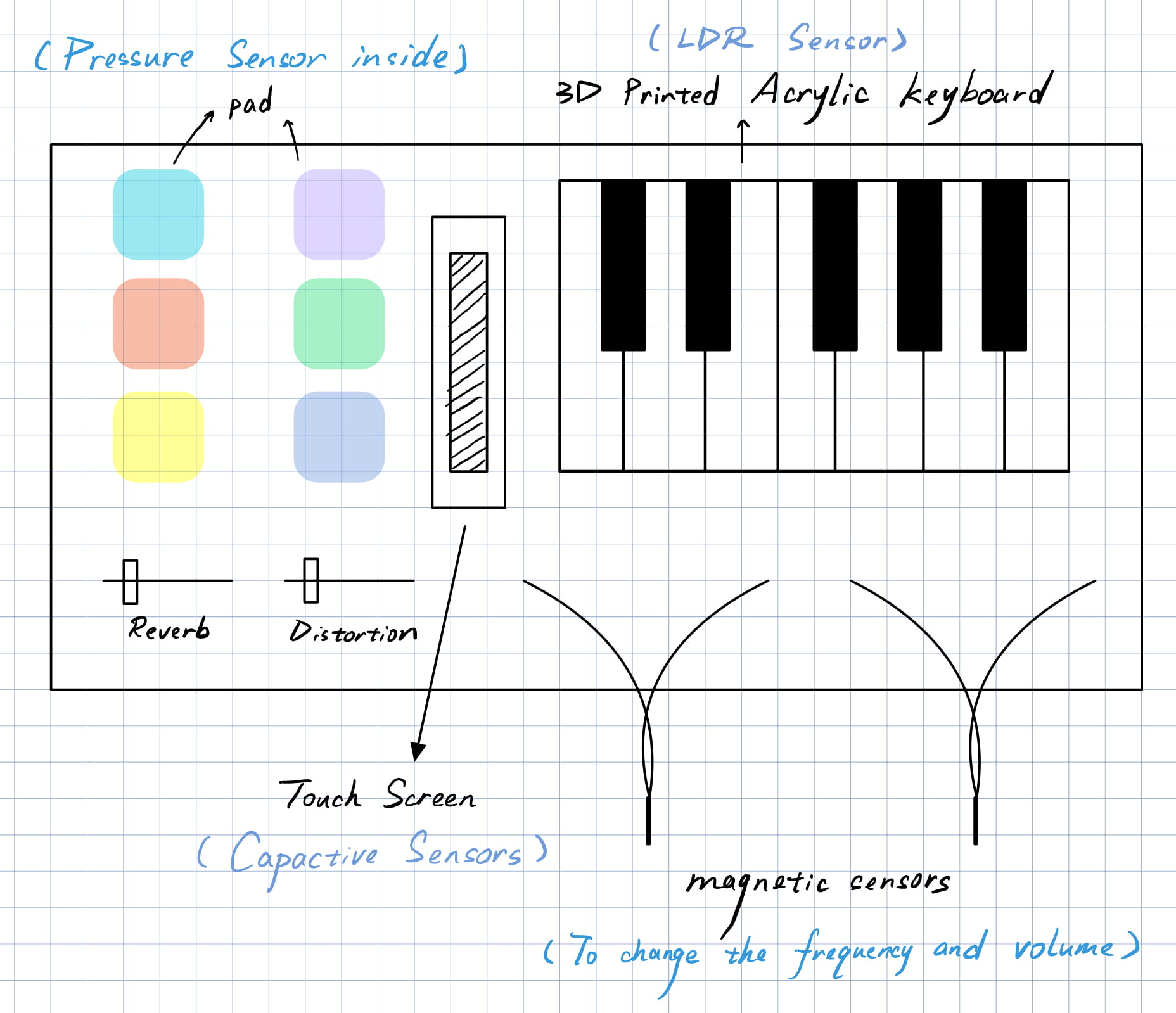
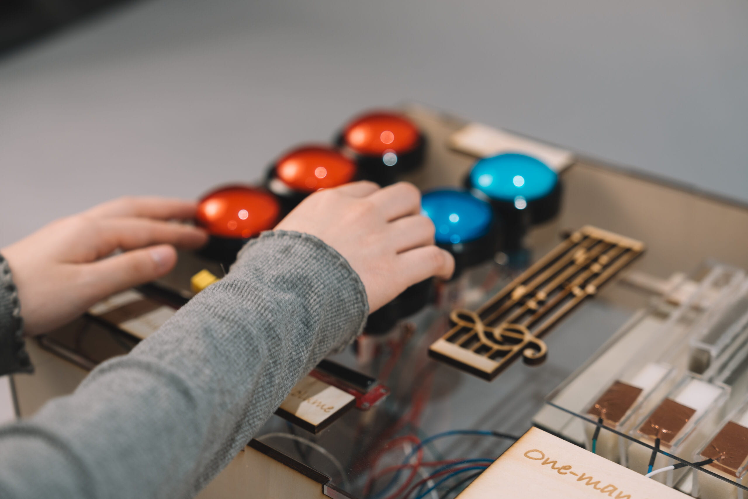
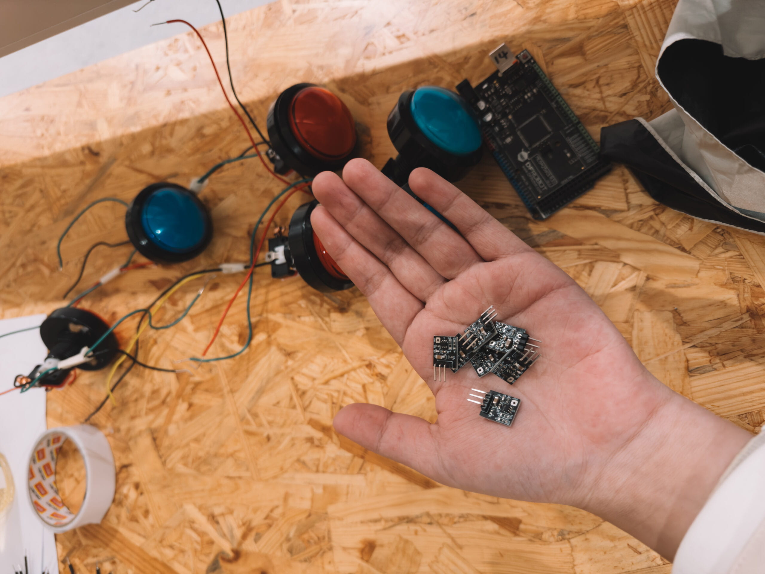
Next, we have the drum section, comprising six sizable buttons. These buttons are not only appropriately sized for ease of use but also respond sensitively, accurately simulating the effect of real drums. With these large buttons, players can effortlessly create rich rhythms and beats, adding rhythm and dynamism to their music.
The final area is dedicated to volume adjustment. We designed this section to allow users to swiftly and accurately adjust the volume to suit various playing environments and styles. This area’s design focuses on usability and flexibility, ensuring that performers can control the loudness of their music in any scenario, thereby perfectly presenting their musical creations.
Overall, this design concept aims to seamlessly blend technology with artistry, providing users with an intuitive and multifunctional platform for musical creation. This approach allows everyone to easily enjoy the pleasure and freedom of music production.
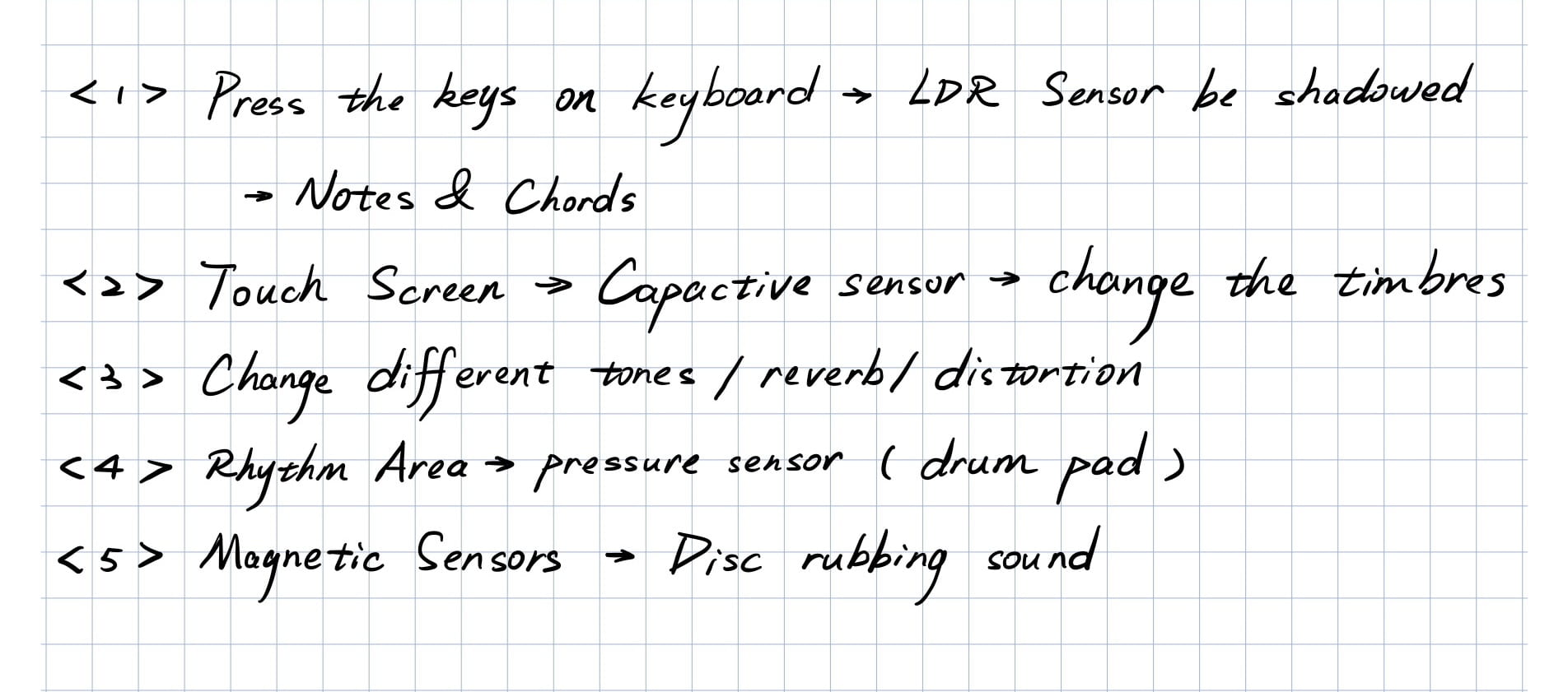
During the user testing session, we realized that we had only created disparate components without integrating them into a cohesive whole. It was Eric who suggested that we use thicker materials to construct a more robust frame, which would significantly enhance the overall stability of the structure. This advice was pivotal in ensuring the durability and reliability of our design.
Another valuable piece of feedback we received was regarding the pressure sensors. It was recommended that we eliminate them altogether in favor of buttons that could reliably trigger the drum sounds. This change was aimed at improving the consistency and responsiveness of the drum section, making it more user-friendly and efficient.
Additionally, we faced challenges with the implementation of the laser-based keyboard. Given the complexity and time constraints, we were advised to consider an alternative solution. The primary focus, we were reminded, should be on completing the functionality of the project rather than on its aesthetic or ‘cool’ factor. This perspective shifted our approach, encouraging us to prioritize practicality and effectiveness over complexity and novelty.
Overall, these suggestions played a crucial role in guiding our project towards a more feasible and user-centered design. They helped us focus on creating a functional and reliable product, ensuring that the end result would meet the practical needs and expectations.
II
FABRICATION AND PRODUCTION
Initially, our vision for the keyboard involved using lasers and springs. The idea was that when a key was pressed, the laser would be obstructed, triggering a sound. However, we soon realized that this concept was overly complex and structurally challenging to implement. Consequently, we pivoted towards using capacitive sensors for the keyboard keys. These sensors detect changes upon touch, offering a more feasible and efficient solution for key sensing. We also found pianos and drums of different colors in our school and other places, and recorded them into our program.
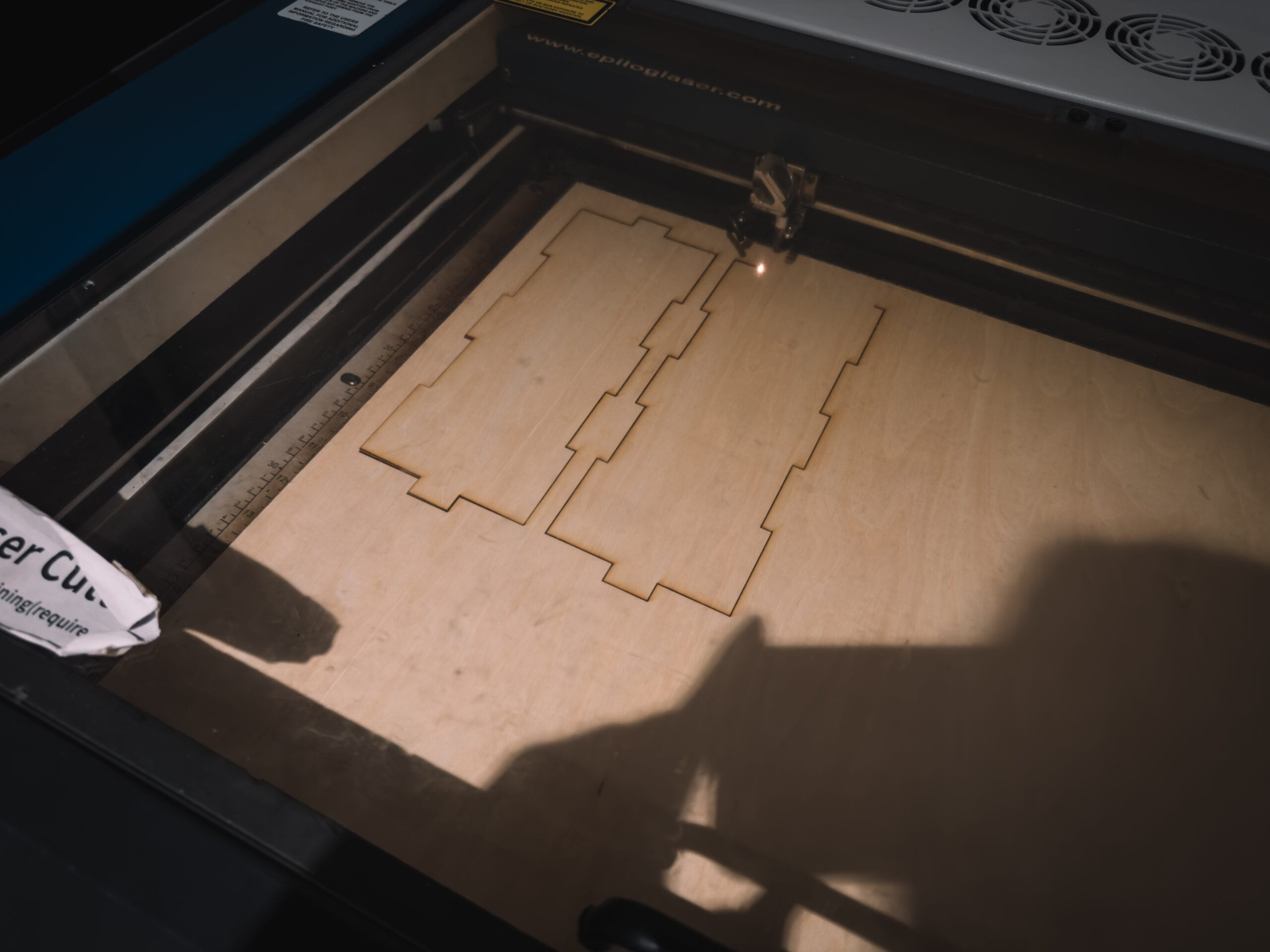
For the drum section, our initial approach was to utilize pressure sensors. However, we faced significant challenges with delay and sensitivity control, which made them impractical for our purposes. After careful consideration, we decided to switch to buttons. This change significantly improved the responsiveness and reliability of the drum pads, allowing for a more accurate and satisfying drumming experience.
Finally, we developed two sliders to independently control the volume of the drum and keyboard sections. These sliders provide a smooth and intuitive way to adjust the sound levels, giving users greater control over their music.
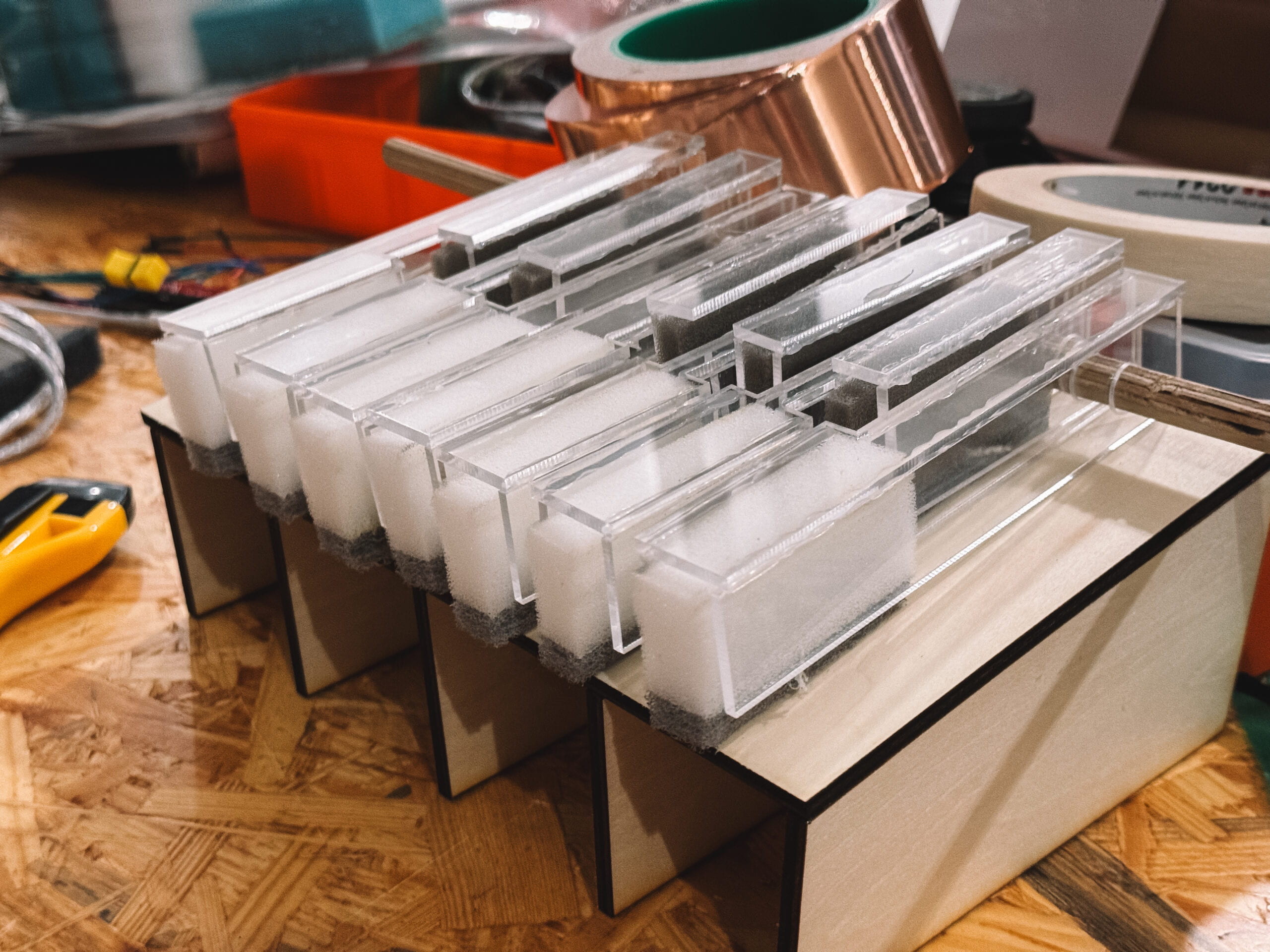
Throughout this process, our key challenge was balancing complexity and functionality. Each time we encountered a hurdle, such as the structural difficulties with the laser-based keyboard or the sensitivity issues with the pressure sensors, we sought out simpler yet effective alternatives. This adaptability in our design approach enabled us to overcome these obstacles, resulting in a user-friendly and efficient musical instrument.
Codes (Arduino Side):
#include

#define NUM_LEDS 60  // How many LEDs in your strip?
#define DATA_PIN 2   // Which pin is connected to the strip's DIN?

CRGB leds[NUM_LEDS];
int next_led = 0;    // 0..NUM_LEDS-1
byte next_col = 0;   // 0..2
byte next_rgb[3];    // temporary storage for next color


// you might want to change these variable
// names to fit your specific sensor
int SENSOR_PIN1 = 14;
int SENSOR_PIN2 = 15;
int SENSOR_PIN3 = 16;
int SENSOR_PIN4 = 17;
int SENSOR_PIN5 = 18;
int SENSOR_PIN6 = 19;
int SENSOR_PIN7 = 20;
int SENSOR_PIN8 = 8;
int SENSOR_PIN9 = 9;
int SENSOR_PIN10 = 10;
int SENSOR_PIN11 = 11;
int SENSOR_PIN12 = 12;
int SENSOR_PIN13 = 13;
int SENSOR_PIN14 = A14;
int SENSOR_PIN15 = A15;

int sensorVal1;
int sensorVal2;
int sensorVal3;
int sensorVal4;
int sensorVal5;
int sensorVal6;
int sensorVal7;
int sensorVal8;
int sensorVal9;
int sensorVal10;
int sensorVal11;
int sensorVal12;
int sensorVal13;
int sensorVal14;
int sensorVal15;


// the setup routine runs once when you press reset:
void setup() {
 // initialize serial communication at 9600 bits per second:
  Serial.begin(115200);
  FastLED.addLeds<NEOPIXEL, DATA_PIN>(leds, NUM_LEDS);
  FastLED.setBrightness(50);  // external 5V needed for full brightness
  leds[0] = CRGB::Red;
  FastLED.show();
  delay(3000);
  leds[0] = CRGB::Black;
  FastLED.show();
  Serial.begin(9600);
 // make the digital sensor's pin an input:
 pinMode(SENSOR_PIN1, INPUT);
 pinMode(SENSOR_PIN2, INPUT);
 pinMode(SENSOR_PIN3, INPUT);
 pinMode(SENSOR_PIN4, INPUT);
 pinMode(SENSOR_PIN5, INPUT);
 pinMode(SENSOR_PIN6, INPUT);
 pinMode(SENSOR_PIN7, INPUT);
 pinMode(SENSOR_PIN8, INPUT);
 pinMode(SENSOR_PIN9, INPUT);
 pinMode(SENSOR_PIN10, INPUT);
 pinMode(SENSOR_PIN11, INPUT);
 pinMode(SENSOR_PIN12, INPUT);
 pinMode(SENSOR_PIN13, INPUT);
 pinMode(SENSOR_PIN14, INPUT);
 pinMode(SENSOR_PIN15, INPUT);


}

// the loop routine runs over and over again forever:
void loop() {

  while (Serial.available()) {
    char in = Serial.read();
    if (in & 0x80) {
      // synchronization: now comes the first color of the first LED
      next_led = 0;
      next_col = 0;
    }
    if (next_led < NUM_LEDS) {
      next_rgb[next_col] = in << 1;
      next_col++;
      if (next_col == 3) {
        leds[next_led] = CRGB(next_rgb[0], next_rgb[1], next_rgb[2]);
        next_led++;
        next_col = 0;
      }
    }
    if (next_led == NUM_LEDS) {
      FastLED.show();
      next_led++;
    }
  }
 // read the input pin:
 sensorVal1 = digitalRead(SENSOR_PIN1);
 sensorVal2 = digitalRead(SENSOR_PIN2);
 sensorVal3 = digitalRead(SENSOR_PIN3);
 sensorVal4 = digitalRead(SENSOR_PIN4);
 sensorVal5 = digitalRead(SENSOR_PIN5);
 sensorVal6 = digitalRead(SENSOR_PIN6);
 sensorVal7 = digitalRead(SENSOR_PIN7);
 sensorVal8 = digitalRead(SENSOR_PIN8);
 sensorVal9 = digitalRead(SENSOR_PIN9);
 sensorVal10 = digitalRead(SENSOR_PIN10);
 sensorVal11 = digitalRead(SENSOR_PIN11);
 sensorVal12 = digitalRead(SENSOR_PIN12);
 sensorVal13 = digitalRead(SENSOR_PIN13);
 sensorVal14 = analogRead(SENSOR_PIN14);
 sensorVal15 = analogRead(SENSOR_PIN15);

 // print out the state of the button:
 Serial.print(sensorVal1);
 Serial.print(",");
 Serial.print(sensorVal2);
 Serial.print(",");
 Serial.print(sensorVal3);
 Serial.print(",");
 Serial.print(sensorVal4);
 Serial.print(",");
 Serial.print(sensorVal5);
 Serial.print(",");
 Serial.print(sensorVal6);
 Serial.print(",");
 Serial.print(sensorVal7);
 Serial.print(",");
 Serial.print(sensorVal8);
 Serial.print(",");
 Serial.print(sensorVal9);
 Serial.print(",");
 Serial.print(sensorVal10);
 Serial.print(",");
 Serial.print(sensorVal11);
 Serial.print(",");
 Serial.print(sensorVal12);
 Serial.print(",");
 Serial.print(sensorVal13);
 Serial.print(",");
 Serial.print(sensorVal14);
 Serial.print(",");
 Serial.print(sensorVal15);

 Serial.println();

 delay(100);  // delay in between reads for stability
}
Codes (Processing Side):
import processing.serial.*;
import processing.sound.*;

Serial serialPort;


int NUM_LEDS = 60;                   // How many LEDs in your strip?
color[] leds = new color[NUM_LEDS];  // array of one color for each pixel

// declare an Frequency analysis object to detect the frequencies in a sound
FFT freqAnalysis;
// declare a variable for the amount of frequencies to analyze
// should be a multiple of 64 for best results
int frequencies = 1024;
// Define the frequencies wanted for our visualization.  Above that treshold frequencies are rarely atteigned and stay flat.
int freqWanted = 128;
// declare an array to store the frequency anlysis results in
float[] spectrum = new float[freqWanted];
// Declare a drawing variable for calculating the width of the
float circleWidth;

// declare three SoundFile objects
SoundFile kick;
SoundFile snare;
SoundFile hihat;
SoundFile hit;
SoundFile gong;
SoundFile bell;

SoundFile c;
SoundFile d;
SoundFile e;
SoundFile f;
SoundFile g;
SoundFile a;
SoundFile b;

SoundFile beat;


int NUM_OF_VALUES_FROM_ARDUINO = 16;  /* CHANGE THIS ACCORDING TO YOUR PROJECT */

/* This array stores values from Arduino */
int arduino_values[] = new int[NUM_OF_VALUES_FROM_ARDUINO];


void setup() {
  size(800, 500);
  background(0);
  kick = new SoundFile(this, "kick.wav");
  snare = new SoundFile(this, "snare.wav");
  hihat = new SoundFile(this, "hihat.aif");
  hit = new SoundFile(this, "hit.wav");
  gong = new SoundFile(this, "gong.aif");
  bell = new SoundFile(this, "bell.wav");

  c = new SoundFile(this, "c.wav");
  d = new SoundFile(this, "d.wav");
  e = new SoundFile(this, "e.wav");
  f = new SoundFile(this, "f.wav");
  g = new SoundFile(this, "g.wav");
  a = new SoundFile(this, "a.wav");
  b = new SoundFile(this, "b.wav");

  beat = new SoundFile(this, "beat.wav");


  circleWidth = width/float(freqWanted);
  // create the Frequency analysis object and tell it how many frequencies to analyze
  freqAnalysis = new FFT(this, frequencies);
  // use the soundfile as the input for the analysis
  freqAnalysis.input(beat);

  printArray(Serial.list());
  // put the name of the serial port your Arduino is connected
  // to in the line below - this should be the same as you're
  // using in the "Port" menu in the Arduino IDE
  serialPort = new Serial(this, "/dev/cu.usbmodem1101", 9600);
}


void draw() {
  // analyze the frequency spectrum and store it in the array
  freqAnalysis.analyze(spectrum);
  printArray(spectrum);
  background(0);

  noStroke();

  // draw circles based on the values stored in the spectrum array
  // adjust the scale variable as needed
  float scale = 600;
  for (int i=0; i<freqWanted; i++) {
    color from = color(200, 0, 100);
    color to = color(107, 160, 204);
    color interB = lerpColor(from, to, 0.015*i);
    fill(interB,80);
    circle(i*circleWidth, height/2, spectrum[i]*scale);
  }

  float progress = beat.position() / beat.duration();
  println(progress);                   // find out where we are in the song (0.0-1.0)


  for (int i=0; i < NUM_LEDS; i++) {   // loop through each pixel in the strip
    color from = color(200, 0, 100);
    color to = color(107, 160, 204);
    color interA = lerpColor(from, to, 0.015*i);
    if (i < spectrum[i] * 66 * NUM_LEDS) {     // based on where we are in the song
      leds[i] = color(interA);      // turn a pixel to red
    } else {
      leds[i] = color(0,0,0);        // or to black
    }
  }


  // you can use sound.position() to create a different animation
  // for different parts of the song, e.g.

  // if (sound.position() < 5) {
  //
  // } else if (sound.position() < 10) {
  //
  // }

  sendColors();                        // send the array of colors to Arduino


  float x = map(arduino_values[13],0,1023,0,1);
  float y = map(arduino_values[14],0,1023,0,1);

  // receive the values from Arduino
  getSerialData();

  // use the values like this:
  if(arduino_values[7] == 1){
    kick.amp(x);
    kick.play();
    delay(100);
  }
  else if(arduino_values[8] == 1){
    snare.amp(x);
    snare.play();
    delay(100);
  }
  else if(arduino_values[9] == 1){
    hihat.amp(x);
    hihat.play();
    delay(100);
  }
  else if(arduino_values[10] == 1){
    hit.amp(x);
    hit.play();
    delay(100);
  }
  else if(arduino_values[11] == 1){
    gong.amp(x);
    gong.play();
    delay(100);
  }
  else if (arduino_values[12] == 1){
    bell.amp(x);
    bell.play();
    delay(100);
  }
  else if (arduino_values[0] == 1){
    c.amp(y);
    c.play();
    delay(100);
  }
  else if (arduino_values[1] == 1){
    d.amp(y);
    d.play();
    delay(100);
  }
  else if (arduino_values[2] == 1){
    e.amp(y);
    e.play();
    delay(100);
  }else if (arduino_values[3] == 1){
    f.amp(y);
    f.play();
    delay(100);
  }
  else if (arduino_values[4] == 1){
    g.amp(y);
    g.play();
    delay(100);
  }
  else if (arduino_values[5] == 1){
    a.amp(y);
    a.play();
    delay(100);
  }
  else if (arduino_values[6] == 1){
    b.amp(y);
    b.play();
    delay(100);
  }
}


void keyReleased()
{

  if(key == 'z'){
    beat.play();
    beat.loop();
  }
  if(key == 'p'){
    beat.stop();
  }
}

// the helper function below receives the values from Arduino
// in the "arduino_values" array from a connected Arduino
// running the "serial_AtoP_arduino" sketch
// (You won't need to change this code.)

void sendColors() {
  byte[] out = new byte[NUM_LEDS*3];
  for (int i=0; i < NUM_LEDS; i++) {
    out[i*3]   = (byte)(floor(red(leds[i])) >> 1);
    if (i == 0) {
      out[0] |= 1 << 7;
    }
    out[i*3+1] = (byte)(floor(green(leds[i])) >> 1);
    out[i*3+2] = (byte)(floor(blue(leds[i])) >> 1);
  }
  serialPort.write(out);
}

void getSerialData() {
  while (serialPort.available() > 0) {
    String in = serialPort.readStringUntil( 10 );  // 10 = '\n'  Linefeed in ASCII
    if (in != null) {
      print("From Arduino: " + in);
      String[] serialInArray = split(trim(in), ",");
      if (serialInArray.length == NUM_OF_VALUES_FROM_ARDUINO) {
        for (int i=0; i<serialInArray.length; i++) {
          arduino_values[i] = int(serialInArray[i]);
        }
      }
    }
  }
}
III
CONCLUSIONS
In conclusion, our project began with the ambitious goal of creating an innovative and user-friendly musical instrument that integrates various technologies to simulate a one-man band experience. Our aim was to design a system that was not only technologically advanced but also accessible and intuitive for users of different skill levels.
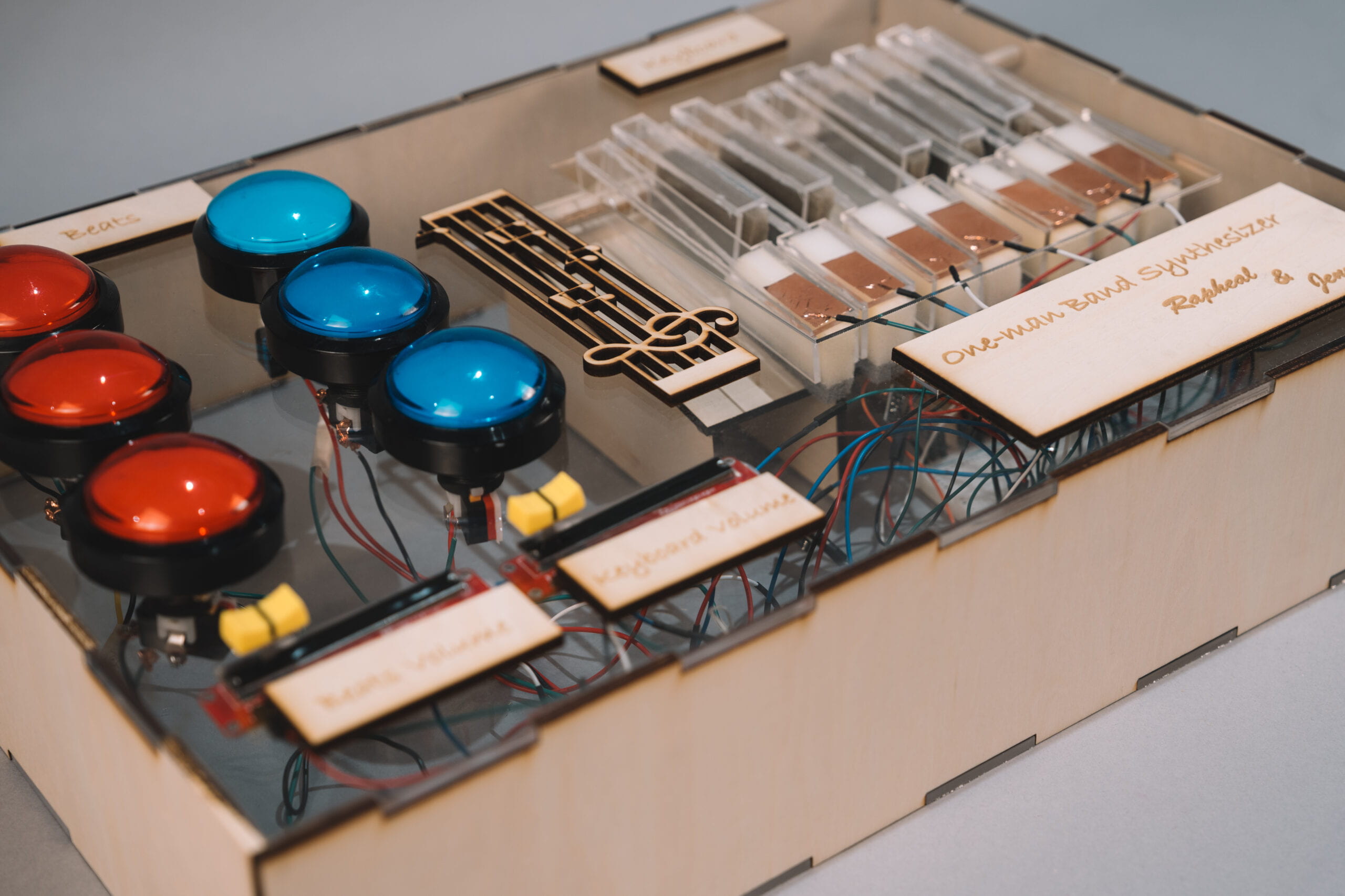
Reflecting on our achievements, it is evident that we largely met our initial objectives. We successfully developed a keyboard and drum interface using capacitive sensors and buttons, respectively, which offered a reliable and responsive musical experience. The introduction of sliders for volume control further enhanced the user interaction, allowing for finer adjustments and a more personalized experience.
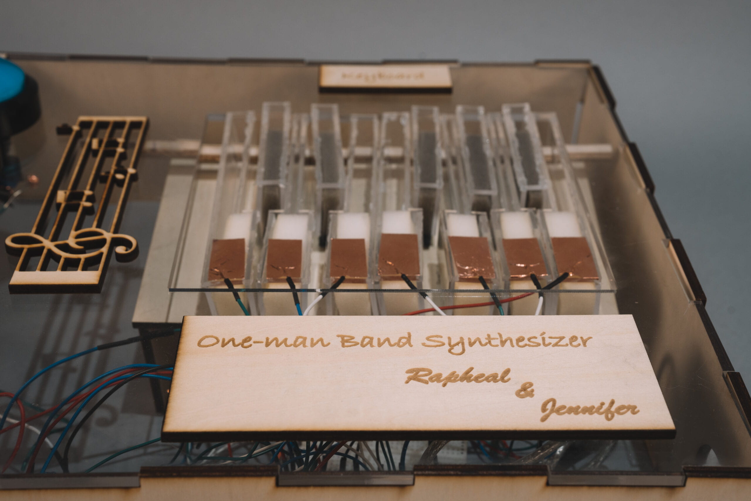
The audience’s interaction with our project was insightful and invaluable. Users engaged with the instrument in ways that demonstrated both the strengths and areas for improvement in our design. Their feedback was instrumental in guiding the final iterations of the project, ensuring that it was not only functionally robust but also aligned with user expectations and needs.
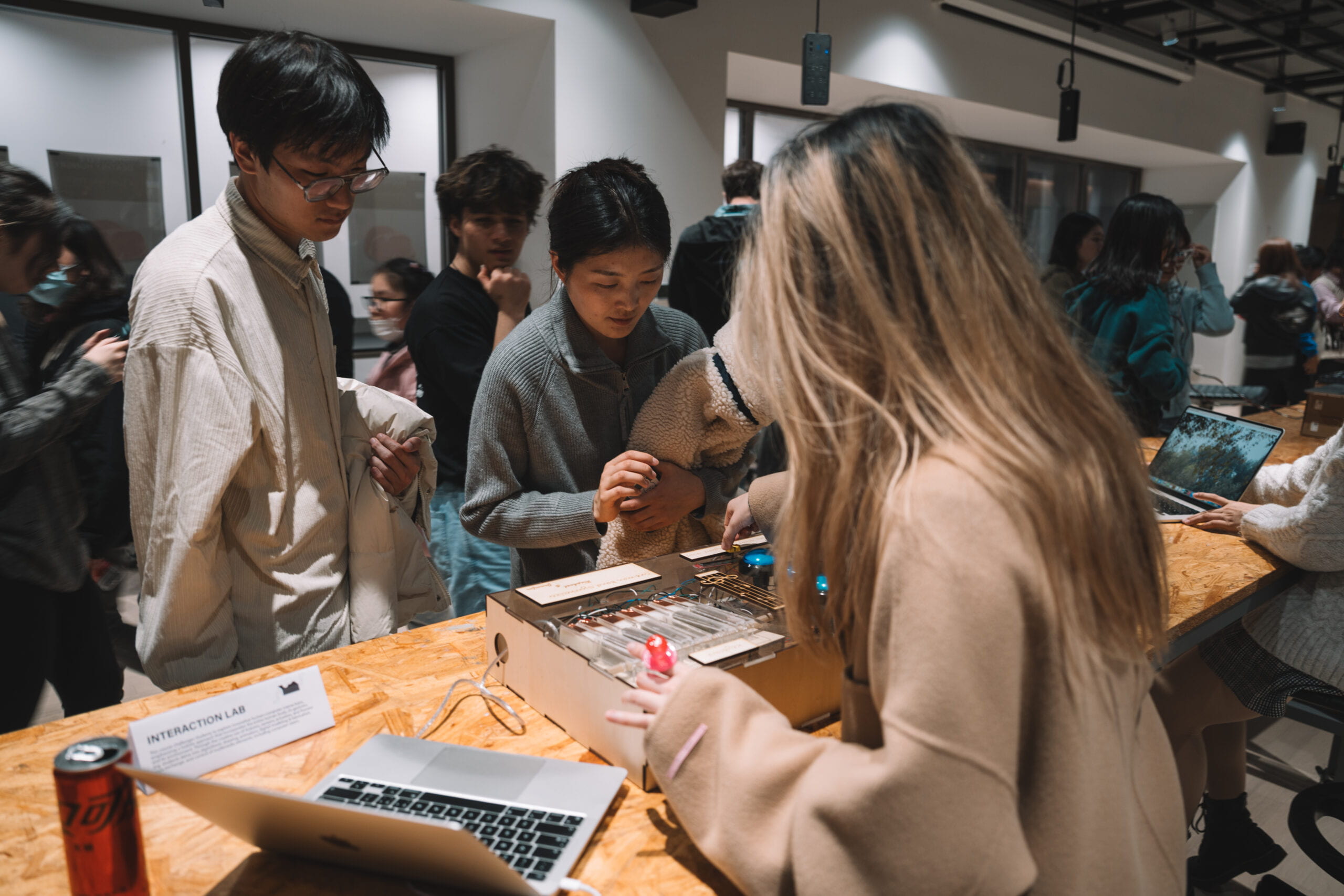
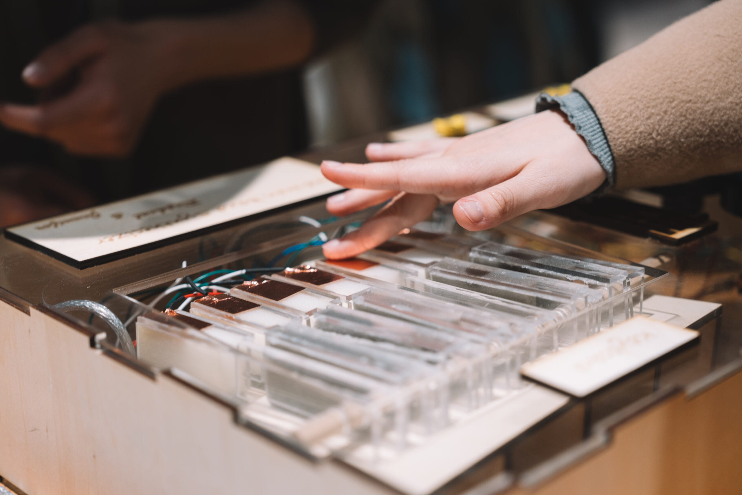
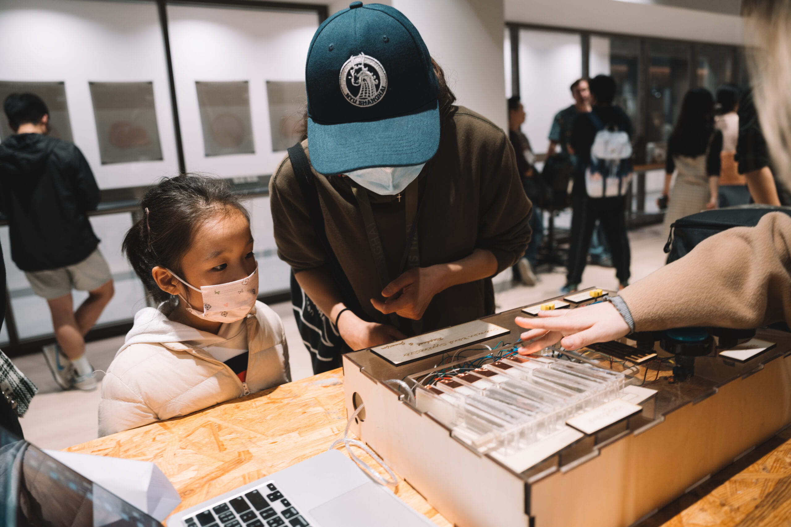
Our project results align well with our definition of interaction, which emphasizes ease of use, responsiveness, and adaptability to user input. However, if given more time, we would focus on further refining the user interface for even greater intuitiveness and exploring additional features that could expand the instrument’s capabilities.
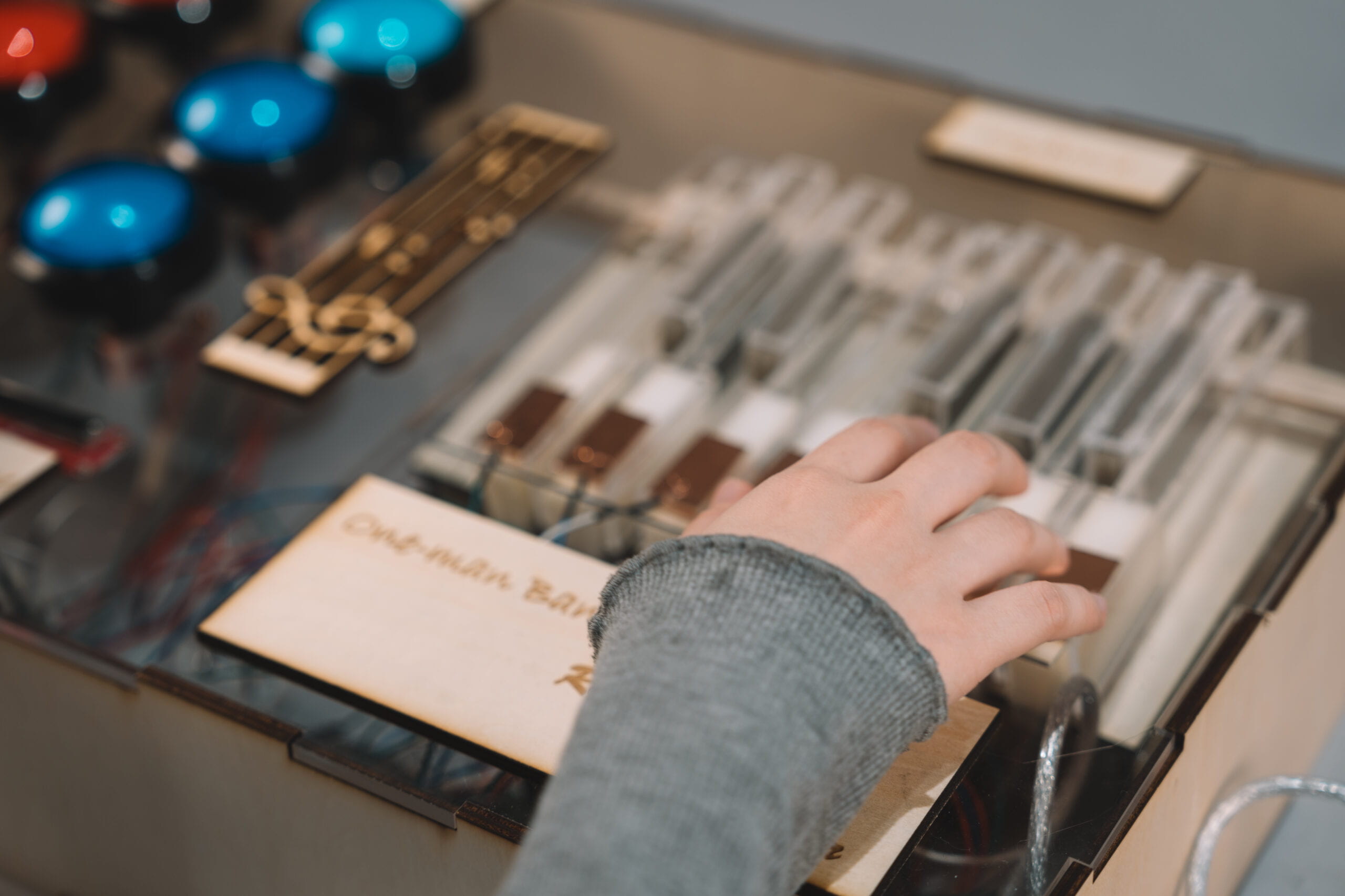
Setbacks and failures, particularly in the initial stages of development, provided critical learning opportunities. They taught us the importance of flexibility in design, the value of user feedback, and the need for iterative testing and refinement. These experiences have enriched our understanding of product development and user experience design.
In summary, our project was a journey of innovation, learning, and adaptation. The accomplishments achieved, coupled with the valuable lessons learned from setbacks, leave us with a profound sense of achievement and a deeper understanding of the intricacies of creating interactive technological solutions. This experience has equipped us with the skills and insights necessary to tackle future challenges in this ever-evolving field.
IV
DISASSEMBLY
V
APPENDIX
The video in the first part: https://youtu.be/f61mC3XbJtw?feature=shared
The screenshot in the first part from: https://www.bilibili.com/video/BV1NX4y1t72q/?spm_id_from=333.337.search-card.all.click&vd_source=0a1be865055d5a40cdfe795a16435b6f
